Images & Videos
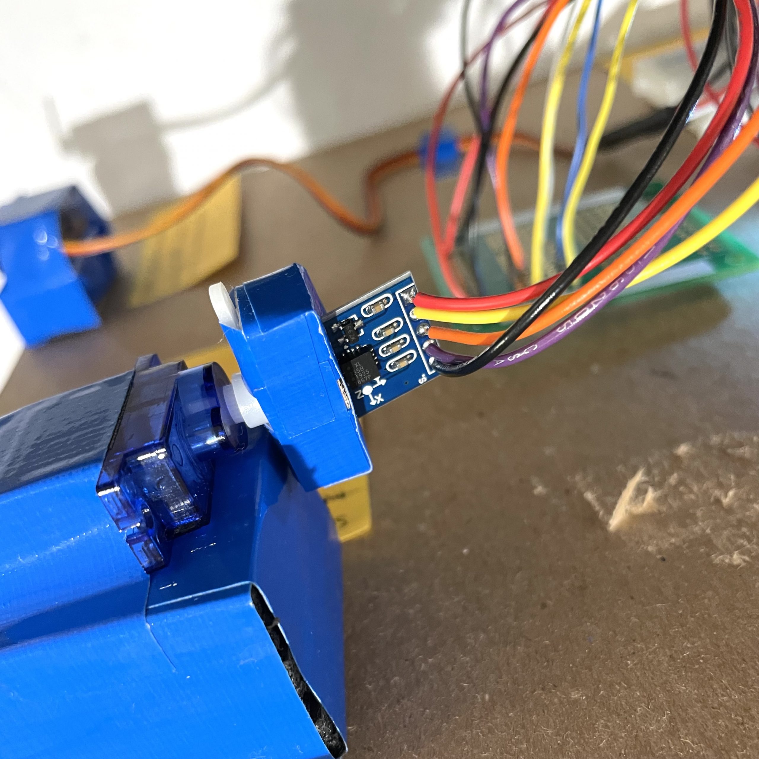
Close-up image of the three-axis accelerometer attached to the servo motor.
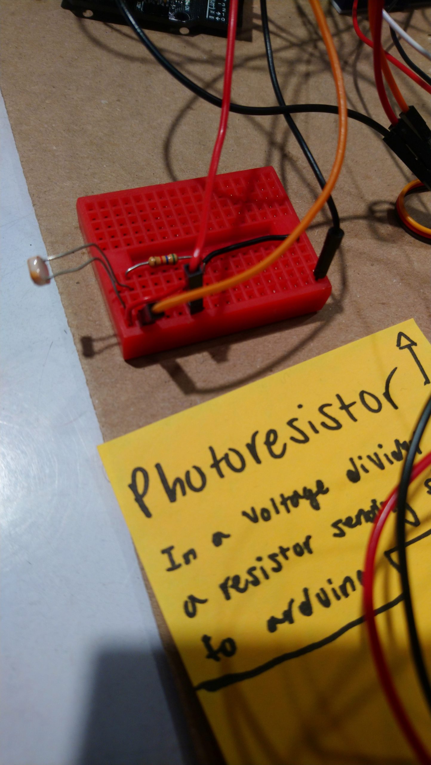
Close-up image of photoresistor and voltage divider circuit.
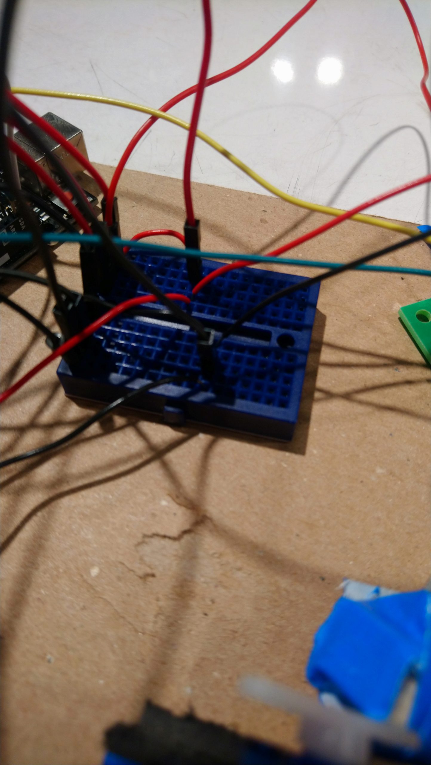
Close-up image of power rail.
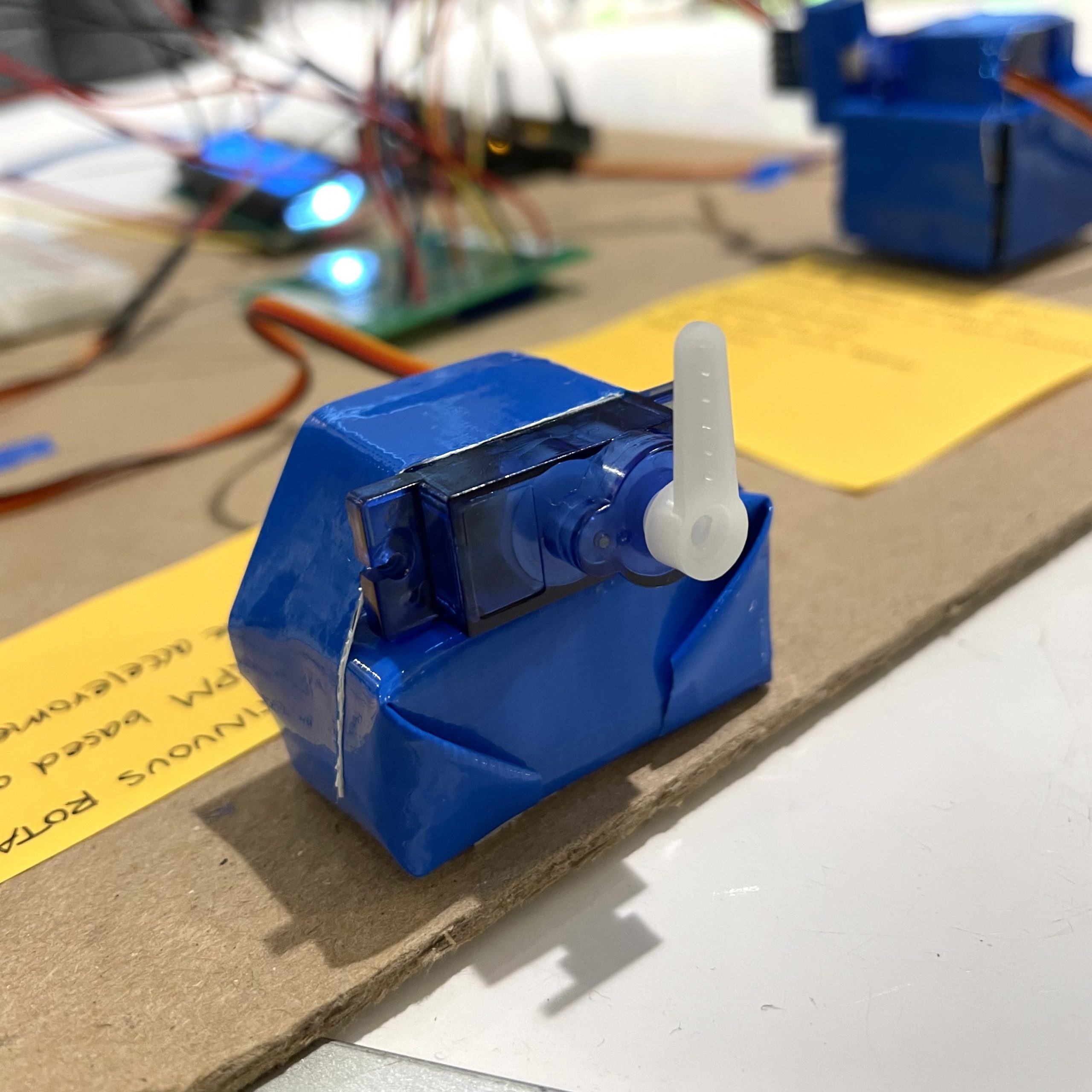
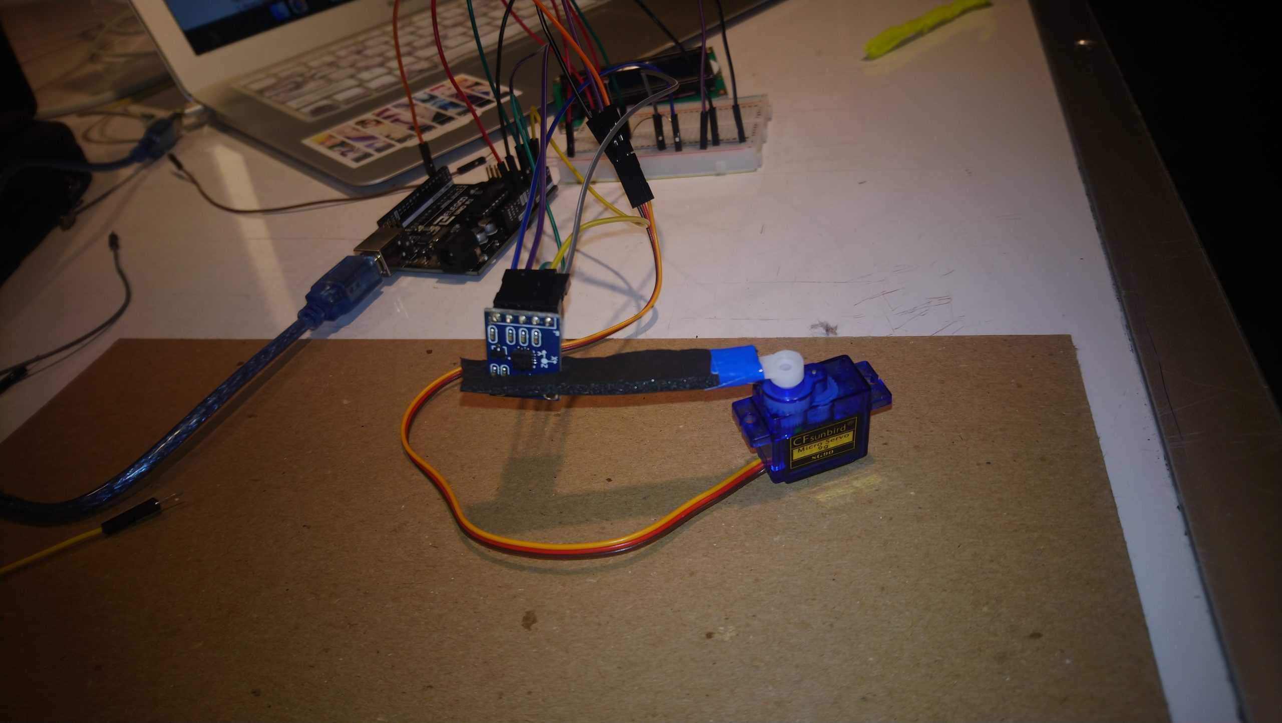
Close-up image of our output, a continuous servo motor that rotates continuously with the speed of around 20 – 60 rpm.
Description
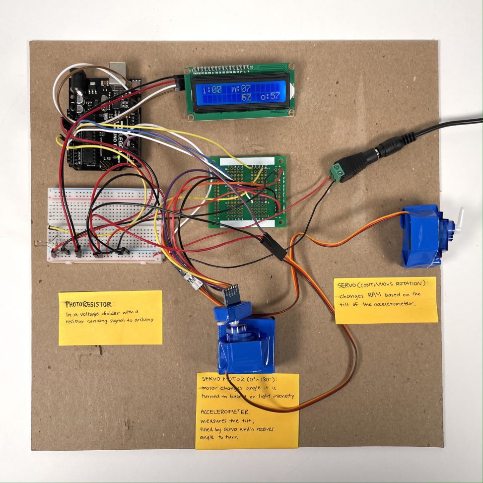
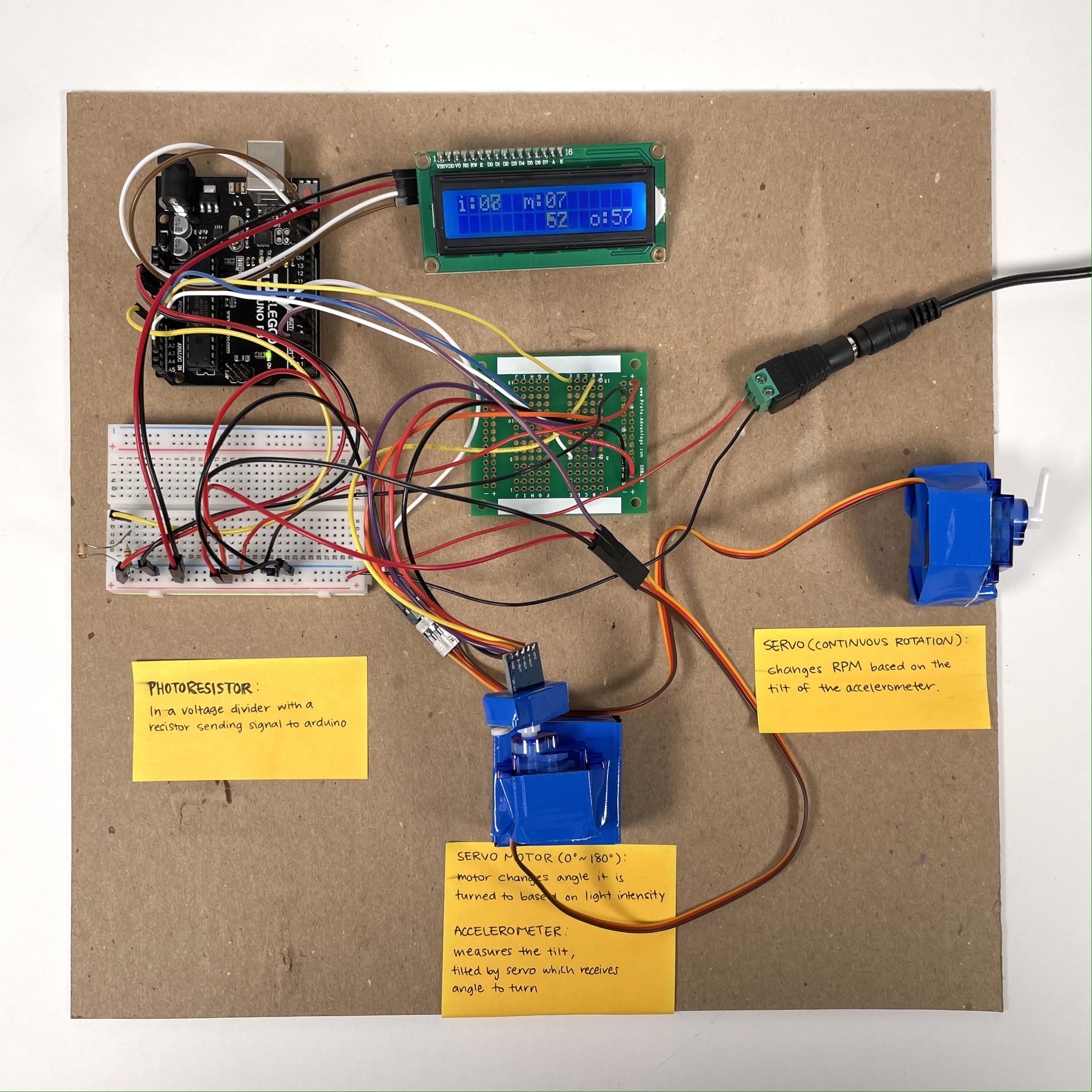
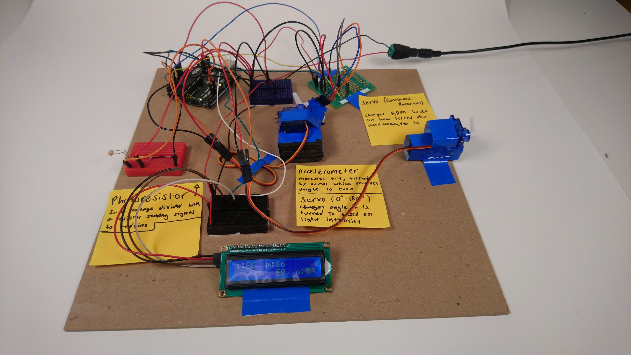
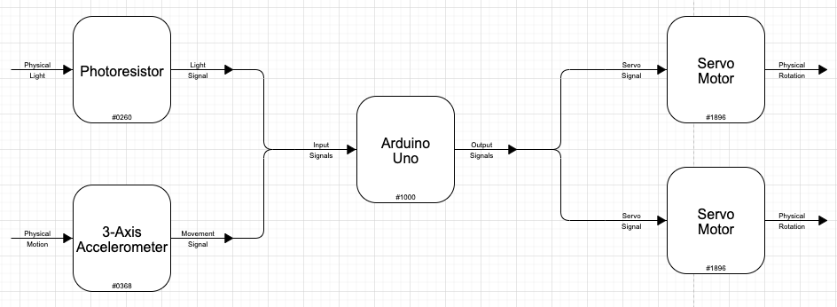
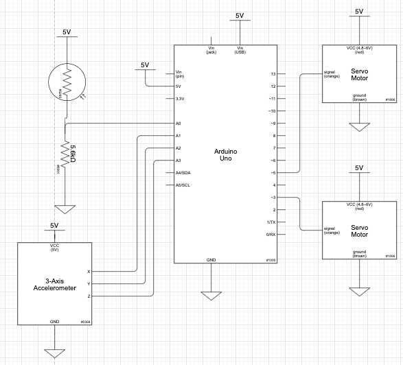
The photoresistor reads light brightness and sends the information to the servo motor which rotates in both directions. The motor turns based on the brightness of light and tilts the three-axis accelerometer that is attached to the servo motor. The accelerometer measures the acceleration in the axes X, Y, and Z and sends information to the continuous motor that rotates continuously in one direction. Based on the tilt of the three-axis accelerometer, the speed of the continuous servo motor changes.
Progress Images
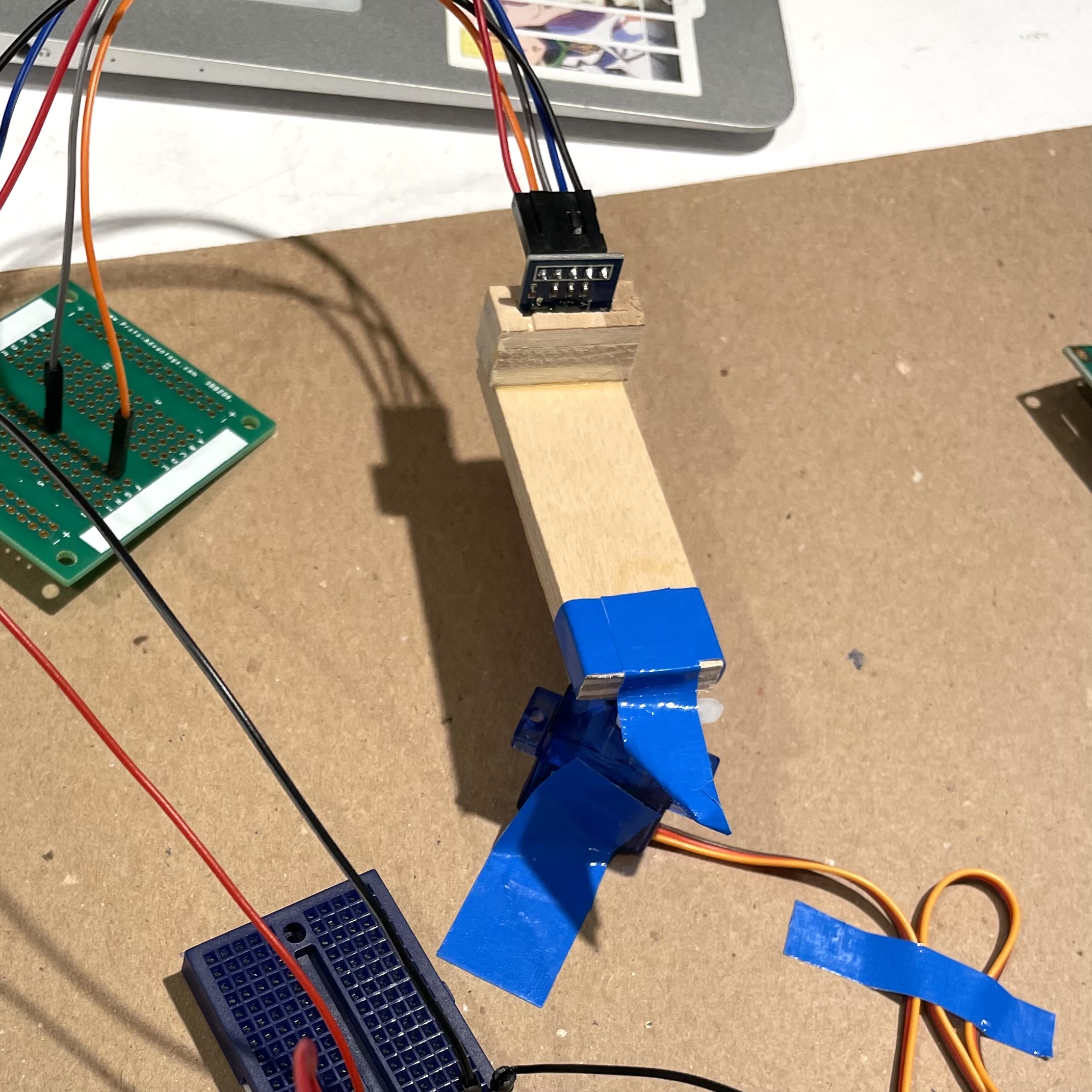
I made this wooden holder to keep the accelerometer in place. We determined that the long stick part of the holder was unnecessary so we decided to cut that part off.
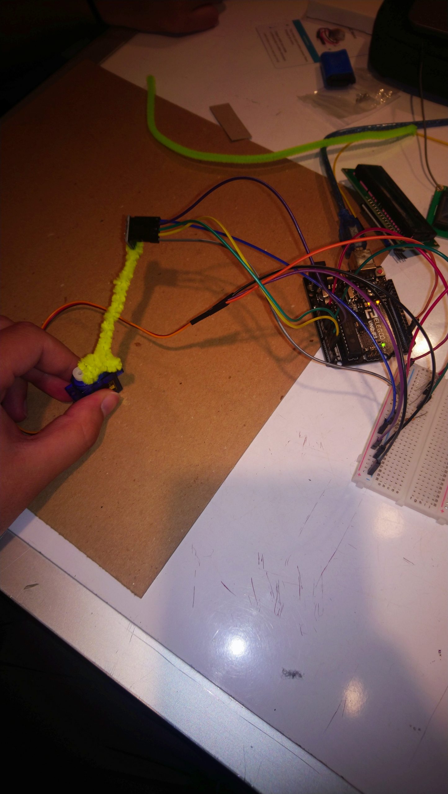
The first attempt at making something that would hold the accelerometer was a pipe cleaner.
We also tried using a bit of styrofoam to hold the accelerometer.
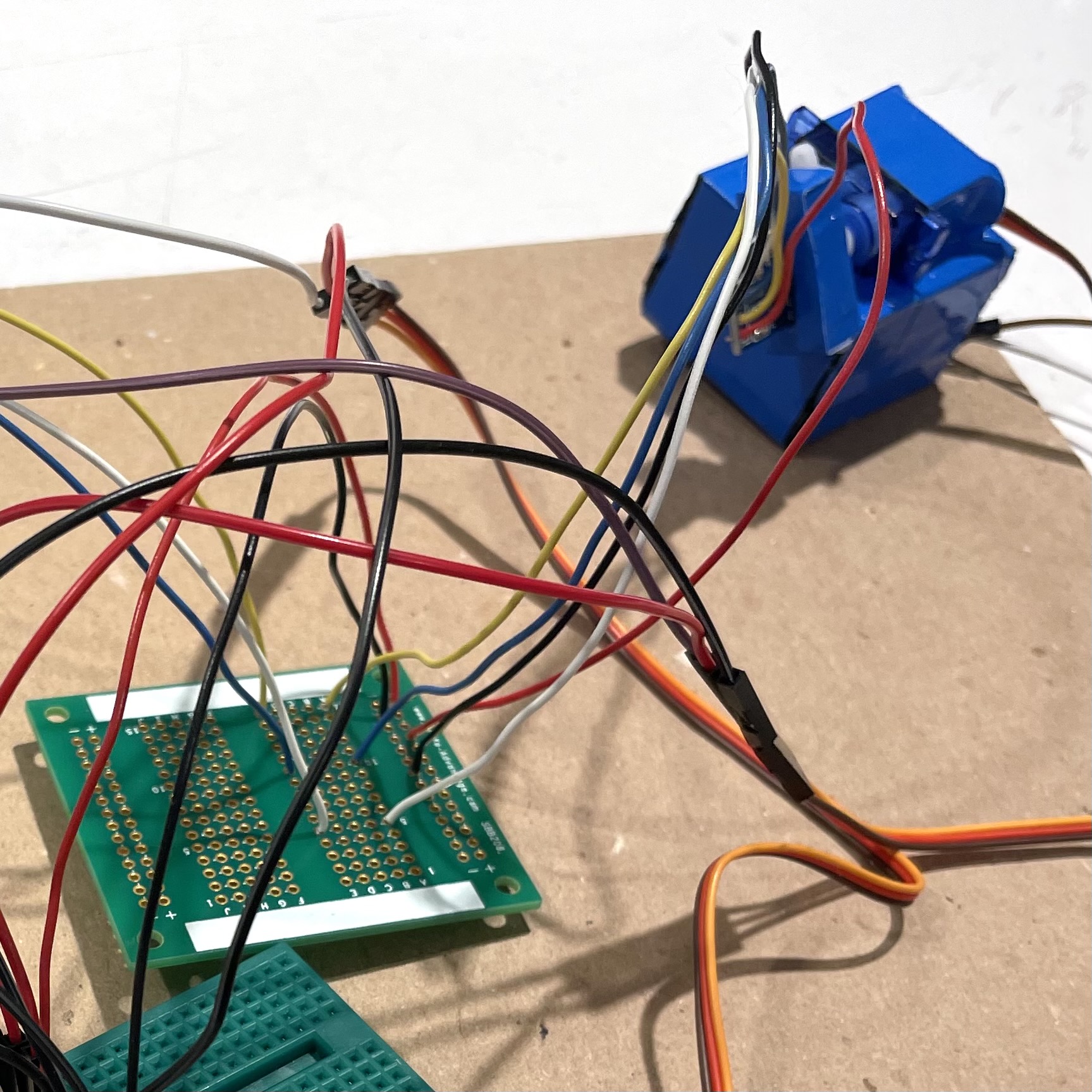
I soldered wires to connect the three-axis accelerometer to the protoboard. I used solid wires at first however it was too stiff causing the movement of the accelerometer to be inflexible as shown above in the image. I later soldered them again using stranded wires.
Discussion
Through this project we learned a lot especially from the challenges we faced and the process of problem solving. One of the challenges we faced was reading the changes in tilt of the three-axis accelerometer. We were reading the acceleration values of all three axes, X, Y, and Z, through the serial monitor as we were tilting the accelerometer, however the changes of the values were so subtle it was difficult to tell which axis we were dealing with. We took the norm of all three values to get one total accelerometer reading using this equation: finalReading = sqrt(X^2 + Y^2 + Z^2). This reading has much more variance than each individual sensor reading.
Another challenge that I faced had to do with soldering. I decided to solder wires connecting the accelerometer to the protoboard and I used solid wires which are pretty stiff making the movement of the accelerometer inflexible. I had to solder them again, but this time I used stranded wires, which are a lot more flexible, easing the movement of the accelerometer.
Through this project, we also learned about a type of motor that we used as our output. Our original plan was to use a stepper motor to produce a continuous rotation however we struggled to figure that out because it required a transistor. However, we came up with an alternative solution. We were introduced to a different type of motor that we could use as our output instead of the stepper motor, which is a continuous servo motor. Unlike a hobby servo motor which rotates only up to 180 degrees, the continuous servo motor rotates 360 degrees continuously, allowing us to produce our output of a continuous rotation of around 20 to 60 rpm. Learning about this new part allowed us to create our output effectively and efficiently.
Functional Block Diagram
Schematic
Code
/*
 * Double Transducer: Light Brightness to Rotational Speed
 *
 * Team: Ronald Gonzalez and Sohye Park
 *
 * Description:
 *   The code reads the light input from the photoresistor
 *   going to pin A0 and then sends the signal generated
 *   to the half rotation servo on pin 3 which will rotate
 *   an accelerometer which sends all 3 of it's signals to
 *   pins A1-3 then the norm of those 3 values is taken and
 *   that is sent to the full rotation servo whose speed
 *   will change based on the signal sent.
 *
 *     Arduino Pin | Description
 *     ------------|---------------------
 *     A0          | PhotoResistor
 *     A1          | Accelerometer x
 *     A2          | Accelerometer y
 *     A3          | Accelerometer z
 *     3           | Half Rotation Servo
 *     5           | Full Rotation Servo
 *
 * Code for Servo from Michael Margolls
 * Code for LED screen from Frank de Brabander
 */

// Libraries
#include <Servo.h>
#include <Wire.h>
#include <LiquidCrystal_I2C.h>

// Pins
#define PHOTORES A0
#define ACCELX A1
#define ACCELY A2
#define ACCELZ A3
#define HALFROTSERVO 3
#define FULLROTSERVO 5

// Servos and Screen
Servo gaugeMotor1;
Servo gaugeMotor2;
LiquidCrystal_I2C screen(0x27, 16, 2);

// Timer
unsigned long lastPrint = 0;

void setup() {

  // Pin setup
  pinMode(PHOTORES, INPUT);
  pinMode(ACCELX, INPUT);
  pinMode(ACCELY, INPUT);
  pinMode(ACCELZ, INPUT);

  // Motor setup
  gaugeMotor1.attach(HALFROTSERVO);
  gaugeMotor2.attach(FULLROTSERVO);

  // Screen setup
  screen.init();
  screen.backlight();
  screen.home();
}

void loop() {

  // Analog reads from photoresistor and accelerometer
  int light = analogRead(A0);
  long accelx = analogRead(A1);
  long accely = analogRead(A2);
  long accelz = analogRead(A3);

  // Taking the norm of all three accelerometer outputs
  long accelFinal = long(sqrt(((accelx * accelx) + (accely * accely) + (accelz * accelz))));

  // Mapping all values to appropriate ranges
  int angle = map(light, 50, 1050, 10, 180);
  int rpm = map(accelFinal, 500, 630, 93, 105);
  int sLight = map(light, 50, 1050, 0, 99);
  int sAngle = map(angle, 10, 180, 0, 99);
  int sRPM = map(rpm, 93, 105, 0, 99);
  int sAccel = map(accelFinal, 500, 620, 0, 99);

  // Sending correct angle and rpm to the two servo motors
  gaugeMotor1.write(angle);
  gaugeMotor2.write(rpm);

  // Delay so both motors aren't being updated at extremely
  // fast rates
  delay(50);

  //Updates screen every 250 milliseconds
  if (millis() - lastPrint >= 250) {
    screen.clear();
    screen.setCursor(0, 0);
    screen.print("i:");
    screen.setCursor(6, 0);
    screen.print("m:");
    screen.setCursor(12, 1);
    screen.print("o:");
    screen.setCursor(2, 0);

    if (sLight < 10){
      screen.print("0");
    }
    screen.print(sLight);
    screen.setCursor(8, 0);
    if (sAngle < 10){
      screen.print("0");
    }
    screen.print(sAngle);
    screen.setCursor(8, 1);
    if (sAccel < 10){
      screen.print("0");
    }
    screen.print(sAccel);
    screen.setCursor(14, 1);
    if (sRPM < 10){
      screen.print("0");
    }
    screen.print(sRPM);
    lastPrint = millis();
  }
}