Jonathan Lindstrom + Frances Adiwijaya
Narrative Description:
Our work uses a little thing which reads how bright the lights are in the room. When it is really bright it will tell a tiny blue thing that turns to move a stick stuck to it up and when it is dark the same tiny blue thing that turns moves the stick down. We then have a small black thing that reads how far between it and the nearest thing. This thing is lined up with the stick so when the lights are low and the thing that turns has the stick down the small black thing will read them as close together and when it is bright it will read them as farther away from each other. If they are close together our work will decide that a second, different thing that turns should go slow and if they are far then the same thing that turns goes faster.
Discussion:
During our project process, we ran into several roadblocks, but ultimately, we managed to power through and get make a cute double transducer.
Our original plan for our middle step was to use a linear actuator to change the height of the lego guy. While originally, it seemed like a good idea, it ended up not working, and we decided to change the middle step into a servo motor several days before the due date. The linear actuator only had two pins, and even using a motor driver, it could only go forwards, backwards, and change the speed of how fast it was moving. This was an issue for us, since we needed the linear actuator to be able to know its position, as we wanted it to change its position value based on the read of the photoresistor. While other groups found ways to work around the linear actuator, we decided to conserve our time and effort and switch to a servo motor, which worked for our purposes just fine. If we had stuck with using the linear actuator, we could have had a completely different product, (for good or for bad, who knows?) but in retrospect, I think we made a good decision to save our time and use an output we were already comfortable with.
I think in the future, it might be a good idea to do the more difficult parts of the project first. We spent a lot of time waiting for the linear actuators to arrive, even though we knew it was the most complicated part. Because we didn’t have a lot of information, we didn’t know that the linear actuators couldn’t sense their position. When they did arrive, we were slightly panicked, as our middle step wasn’t feasible. It might have been good to have a backup plan at that time, instead of coming up with one on the fly after the linear actuators were delivered.
I am also very glad that we had tried to line our output up with group 2’s input the night before the project. Because we tried everything the night before, when we ran into some issues, e.g. having our motor be too fast and not powerful enough, we had some time to change motors.
As a student with no experience in hardware nor software, I learned a lot during this project. I soldered for the first time, spent a lot of time debugging code, and did a lot of googling on Arduino sensors. We ran into several roadblocks, such as issues with our DC motor, LCD displays, as well as our linear actuator, but ultimately, our problem solving led to a successful end product.
Story Behind Our Project:
When we were building our transducers we thought that the mess of wires and such kind of looked like an alien planet. So we decided to base our project off Star Wars. Specifically the battle of Umbara. In this battle the droid army has control over the planet and is using it as their primary supply chain. The two clones are attempting to battle the droid army and take control of the Umbaran capital (the arduino + the lego tower) to cut off this supply chain.
Final Images:

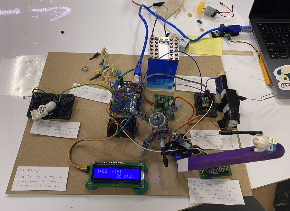
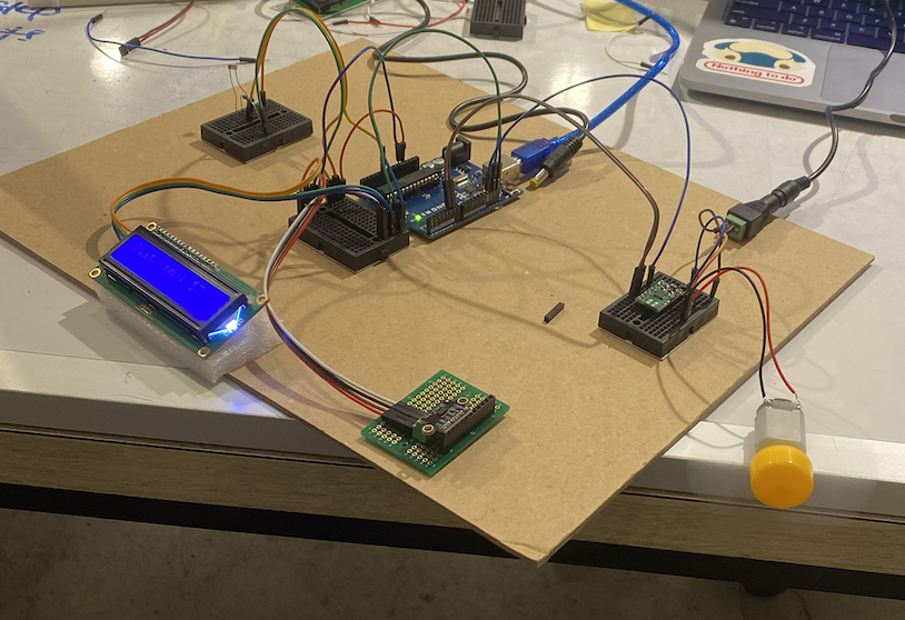
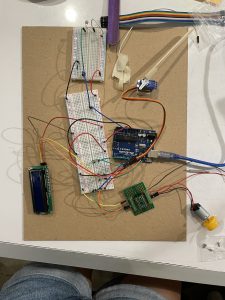
Jonathan’s Final Image
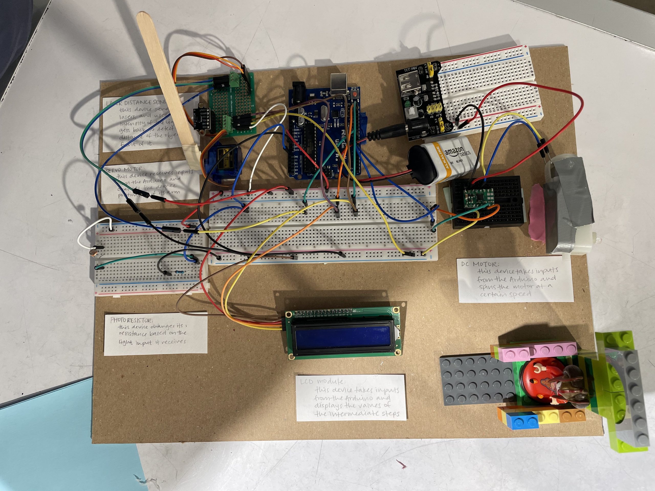
Frances’s Final Image
Detail Photos:
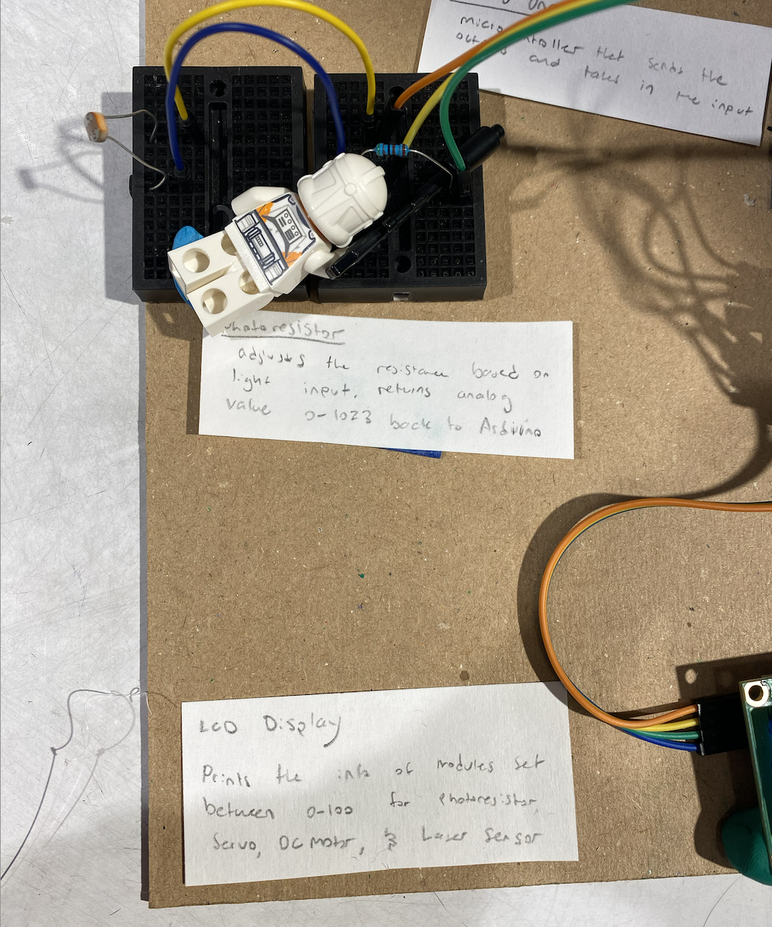
This is the other main function of our project, the photoresistor. It will take in light and return an analog value based on the intensity of the light around it. You can see a clone hiding in the wires attacking the droids in the image below.
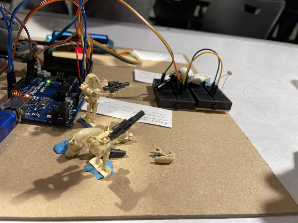
A nice focus shot of the droids and the lego pieces that make up the story of our double transducer.
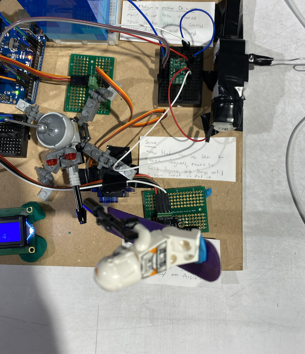
A close up of our servo motor. We have attached a popsicle stick so it covers the laser distance sensor below. Furthermore you can see the clone using the popsicle stick as leverage to attack the Spider Droid below.
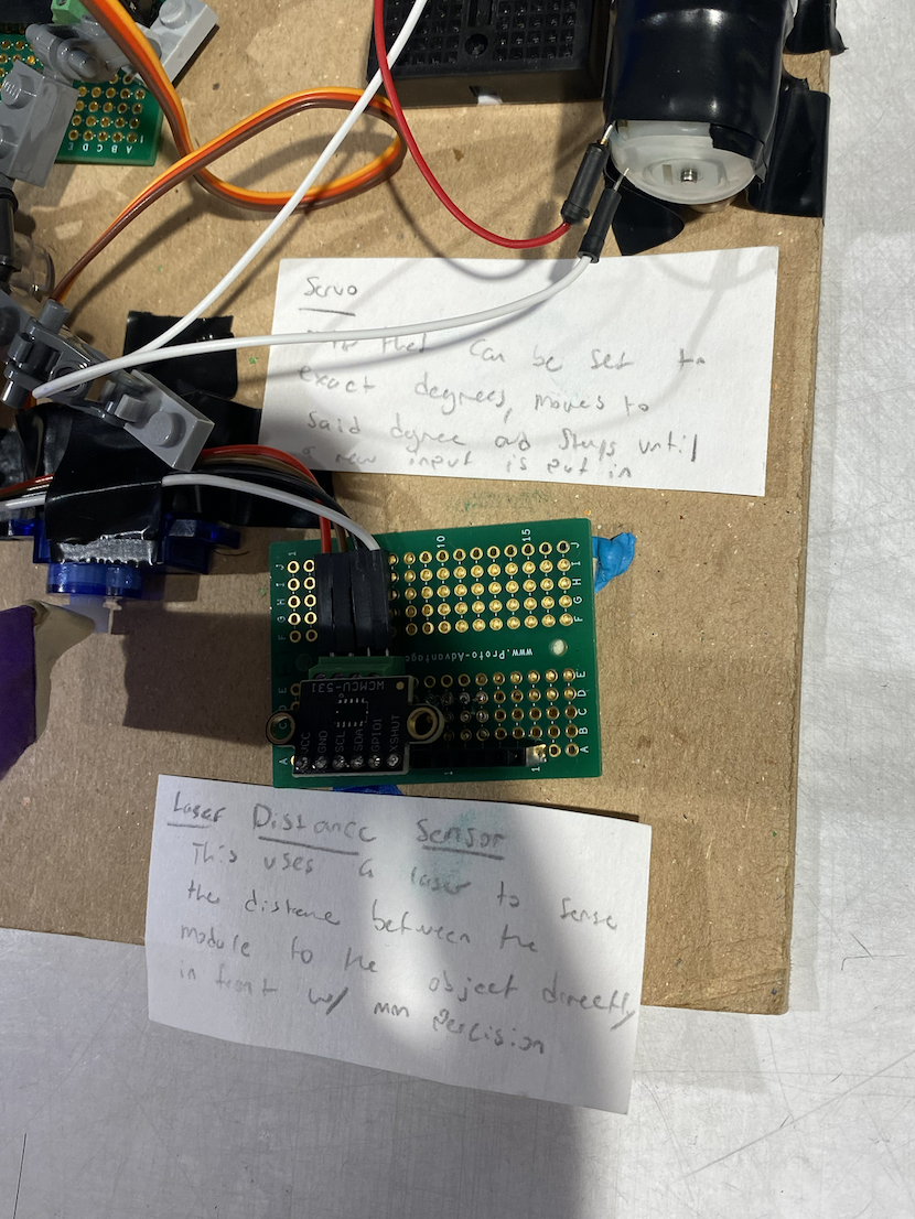
Close up of our laser distance module. This reads how far the distance from the popsicle stick above it is.
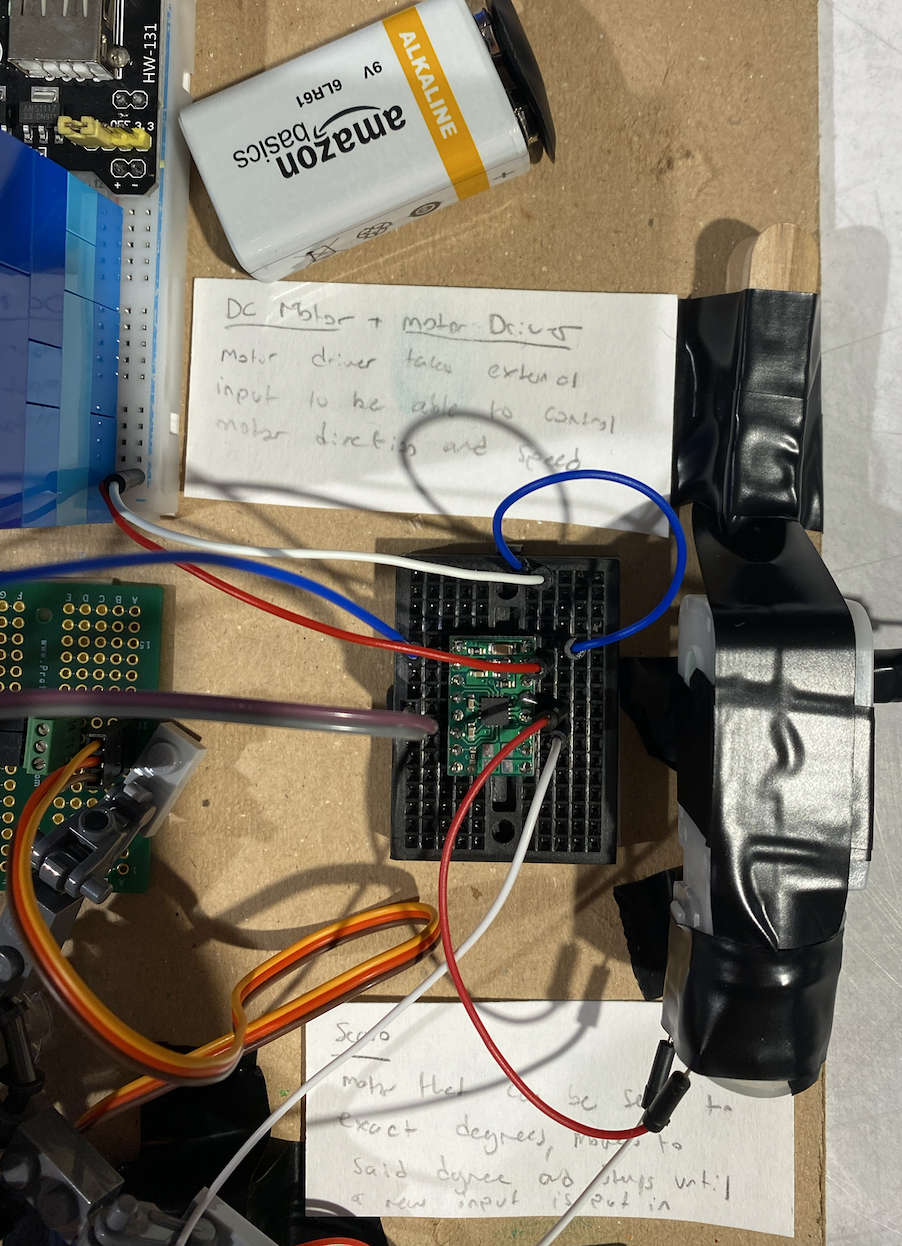
This shot highlights one of the main functions of our project, the motor driver and DC motor
Working Videos of Both Projects:
Progress Images:
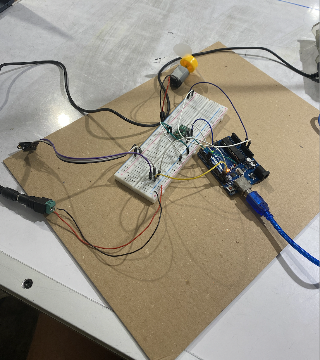
Jonathan Progress Image #1: In this I got the laser sensor and motor working together so that changes in the laser sensor resulted in decreased or increased motor speed
Jonathan Progress Image #2: In this I took our success in Progress Image and I #1 and added the lcd and phototransistor so that the lcd will display the values of the laser sensor, motor, and phototransistor
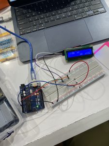
Frances Progress Image #1: LCD Display working with the photoresistor. Photoresistor values would display in the LCD screen.
Frances Progress Image #2: Trying to figure out how to run the DC motor through the motor driver.
Video of the servo motor and the laser distance sensor working:
Schematics and Block Diagrams:
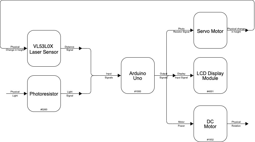
Block Diagram representing the inputs and outputs of our project
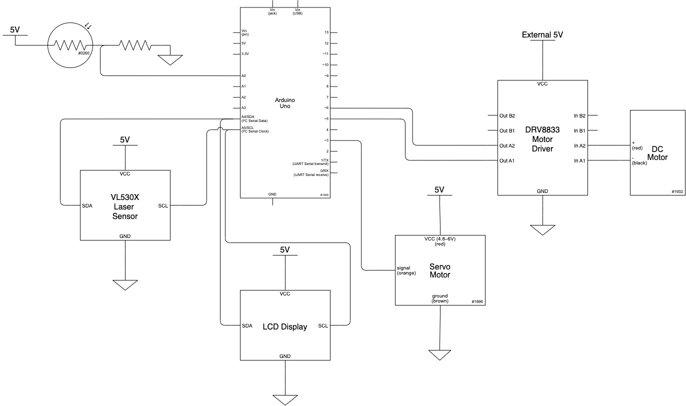
Electrical Schematic of our final project
Code:
/*
  Double Transducer Project: from light brightness to rotational speed
    Frances Adiwijaya and Jonathan Lindstrom
  Description:
    In this project, we had to create a device that would use double transduction,
    and convert the brightness of light to rotational speed.
    We decided to use a servo's position and a laser distance sensor to be our
    intermediate transduction.
  Pin Mapping:
     Arduino pin | description
   ------------- |-------------
   A0             Photoresistor
   5              DC Motor Driver
   6              DC Motor Driver
   3              Servo Motor
   SDA            SDA pin, LCD Display/Laser Distance Sensor (VL53L0X)
   SCL            SCL pin, LCD Display/Laser Distance Sensor (VL53L0X)
  References:

*/

// import Libraries
#include "Adafruit_VL53L0X.h"
#include <Wire.h>
#include <LiquidCrystal_I2C.h>
#include <Servo.h>

Adafruit_VL53L0X lox = Adafruit_VL53L0X();

LiquidCrystal_I2C screen(0x27, 16, 2);
Servo gaugeMotor;

// set the variables for the pins
const int MOTORPIN1 = 5;
const int MOTORPIN2 = 6;
const int PHOTORESISTORPIN = A0;
const int GAUGEMOTORPIN = 3;
const int QUARTERWAIT = 250;
unsigned long quarterTimer = 0;

void setup() {
  // initialize the pins and LCD
  screen.init();
  screen.backlight();
  pinMode(MOTORPIN1, OUTPUT);
  pinMode(MOTORPIN2, OUTPUT);
  pinMode(PHOTORESISTORPIN, INPUT);
  gaugeMotor.attach(GAUGEMOTORPIN);

  digitalWrite(MOTORPIN1, LOW);
  digitalWrite(MOTORPIN2, LOW);
  Serial.begin(9600);


  //Setting up the laser sensor
  while (! Serial) {
    delay(1);
  }
  Serial.println("Adafruit VL53L0X test");
  if (!lox.begin()) {
    Serial.println(F("Failed to boot VL53L0X"));
    while(1);
  }
  Serial.println(F("VL53L0X API Simple Ranging example\n\n"));
}


// DC motor functions
void set_motor_pwm(int pwm, int IN1_PIN, int IN2_PIN)
{
  if (pwm < 0) {  // reverse speeds
    analogWrite(IN1_PIN, -pwm);
    digitalWrite(IN2_PIN, LOW);

  } else { // stop or forward
    digitalWrite(IN1_PIN, LOW);
    analogWrite(IN2_PIN, pwm);
  }
}
void set_motor_currents(int pwm_A)
{
  set_motor_pwm(pwm_A, MOTORPIN1, MOTORPIN2);
}
void spin_and_wait(int pwm_A)
{
  set_motor_currents(pwm_A);
}

void loop() {
  // assigning a variable to the light input
  int lightVal;
  lightVal = analogRead(PHOTORESISTORPIN);
  lightVal = map(lightVal, 220, 1000, 0, 100);

  // laser sensor stuff
  VL53L0X_RangingMeasurementData_t measure;
  Serial.print("Reading a measurement... ");
  lox.rangingTest(&measure, false); // pass in 'true' to get debug data printout!
  if (measure.RangeStatus != 4) {  // phase failures have incorrect data
    int distanceVal = measure.RangeMilliMeter;
    Serial.print("Distance (mm): "); Serial.println(distanceVal);
  } else {
    Serial.println(" out of range ");
  }

  // set a variable for the servo's position, and change it based on the photoresistor value
  int motorPos = 0;
  motorPos = map(lightVal, 0, 100, 170, 92);
  gaugeMotor.write(motorPos);

  // change the motor speed depending on the laser sensor's read
  int motorspeed = map(measure.RangeMilliMeter, 20, 100, 65, 194);
  set_motor_currents(motorspeed);

  // store the laser sensor's read in a variable
  int distanceVal = measure.RangeMilliMeter;

  if ((millis() - quarterTimer) >= QUARTERWAIT) {

    //print the intermediate values (mapped)

    screen.clear();
    screen.home();
    screen.print("i:");
    screen.print(lightVal);

    screen.setCursor(6, 0);
    screen.print("m:");

    motorPos = map(motorPos, 170, 92, 0, 99);
    screen.print(motorPos);

    screen.setCursor(8, 1);
    distanceVal = map(distanceVal, 20, 100, 0, 100);
    screen.print(distanceVal);

    screen.setCursor(12, 1);
    screen.print("o:");
    motorspeed = map(motorspeed, 65, 194, 0, 100);
    screen.print(distanceVal);

    quarterTimer = millis();
  }

}