
Elise Chapman, Remington Frank, Sharon Li, Sarah Yun
Simple Narrative Description
The machine sees the color on the paper strip, then uses that color to extend a motor a certain distance. That distance is detected and is used to angle a stick to a proportional degree.
Technical Description
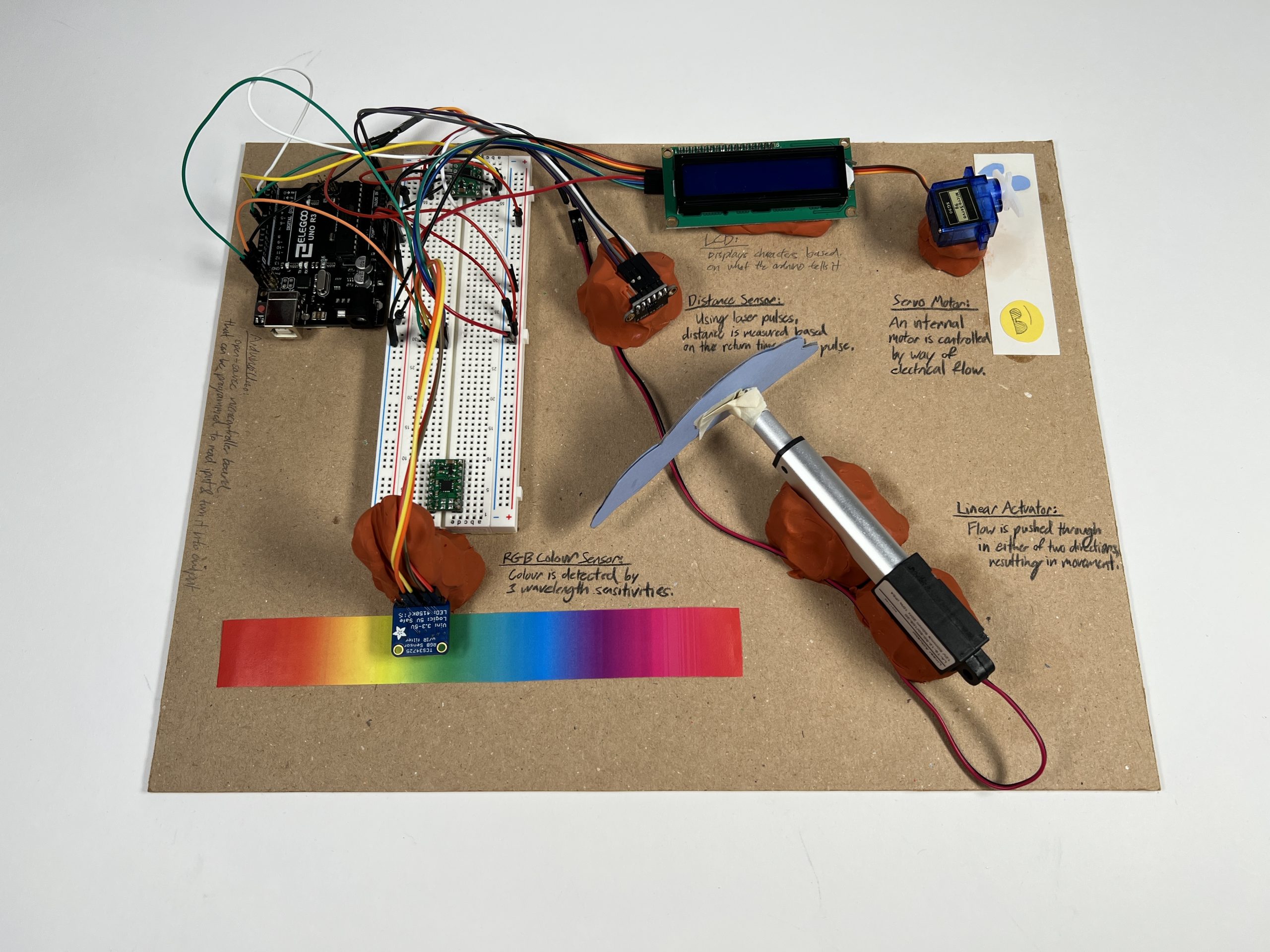
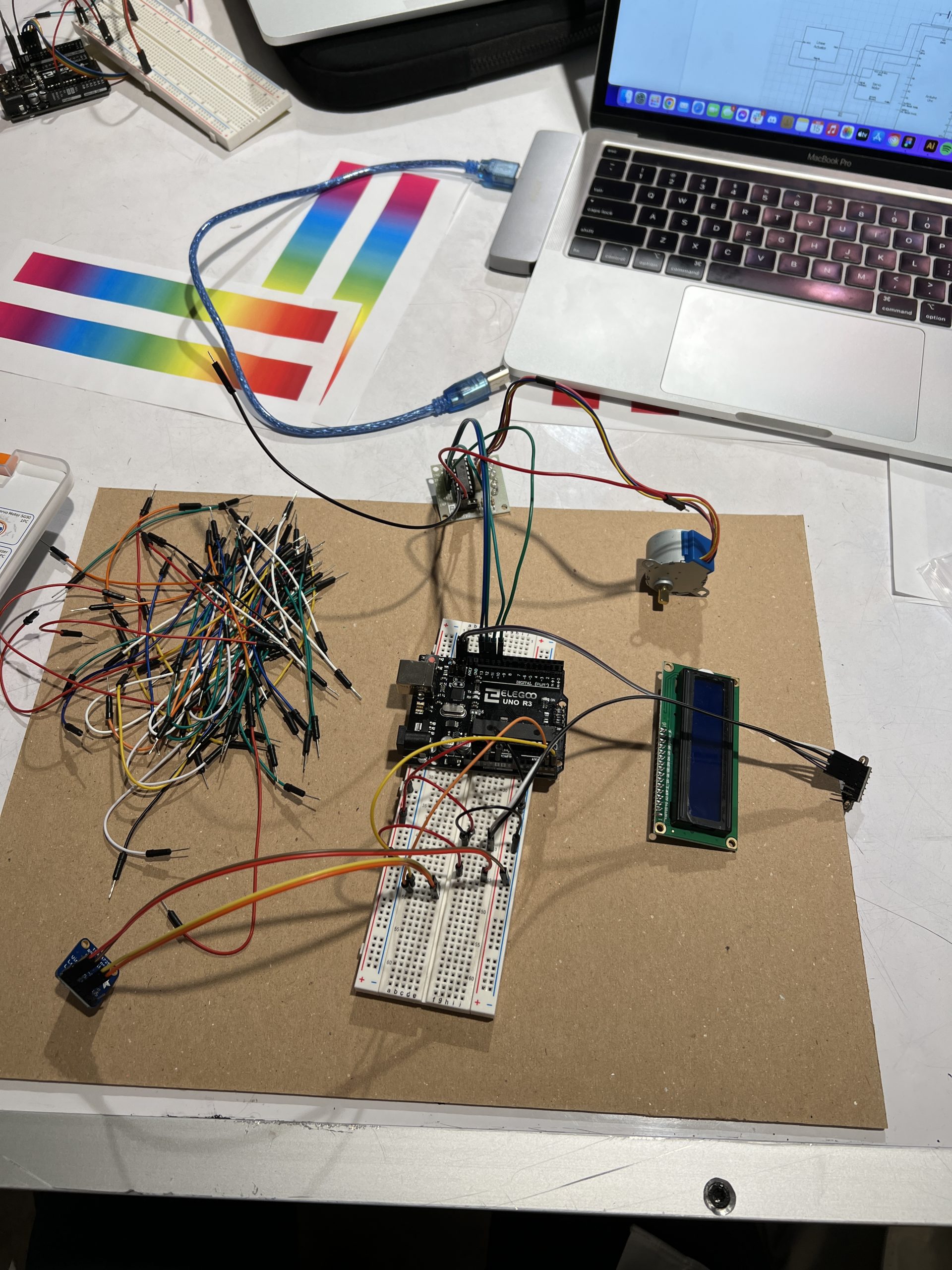
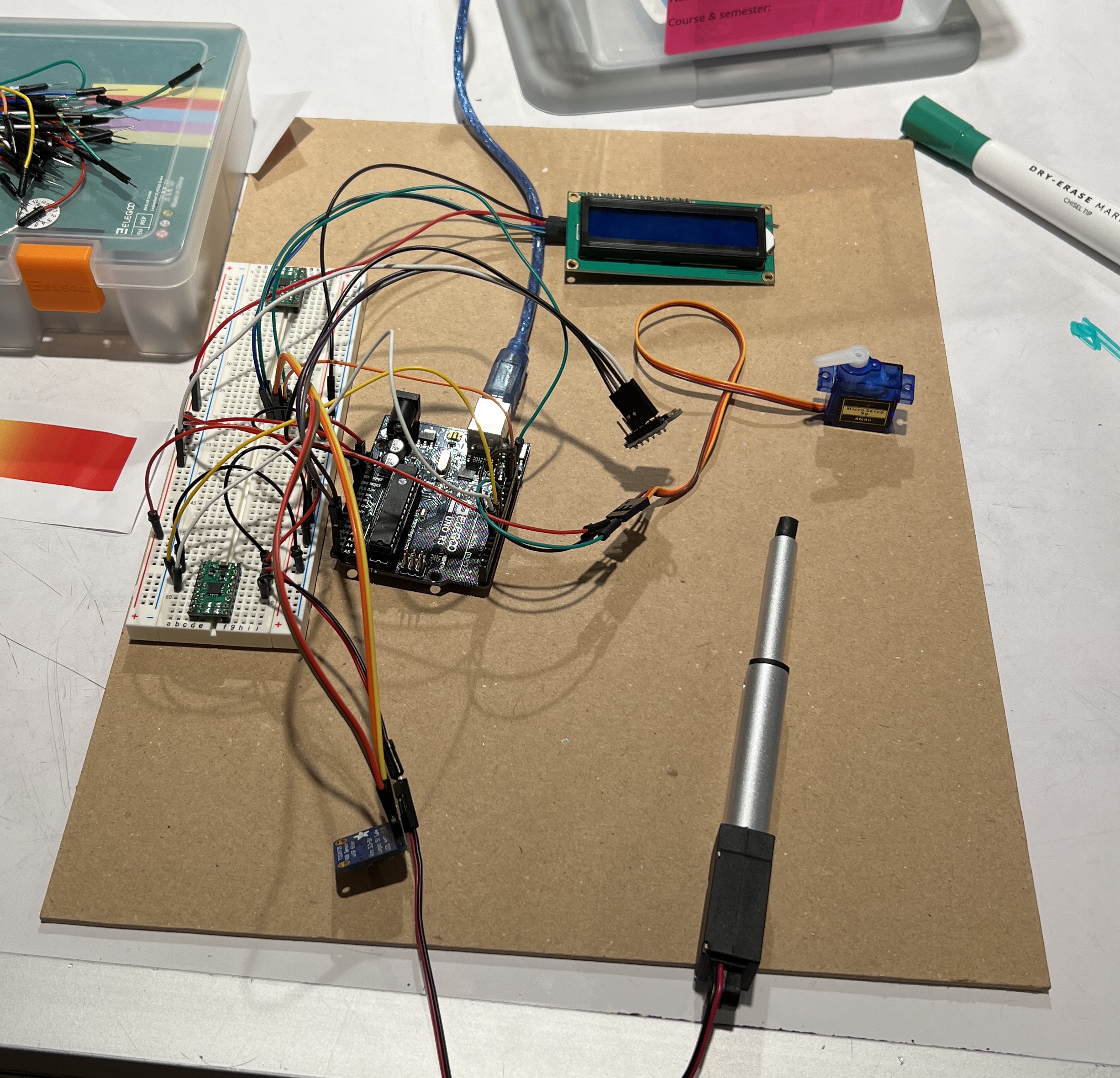
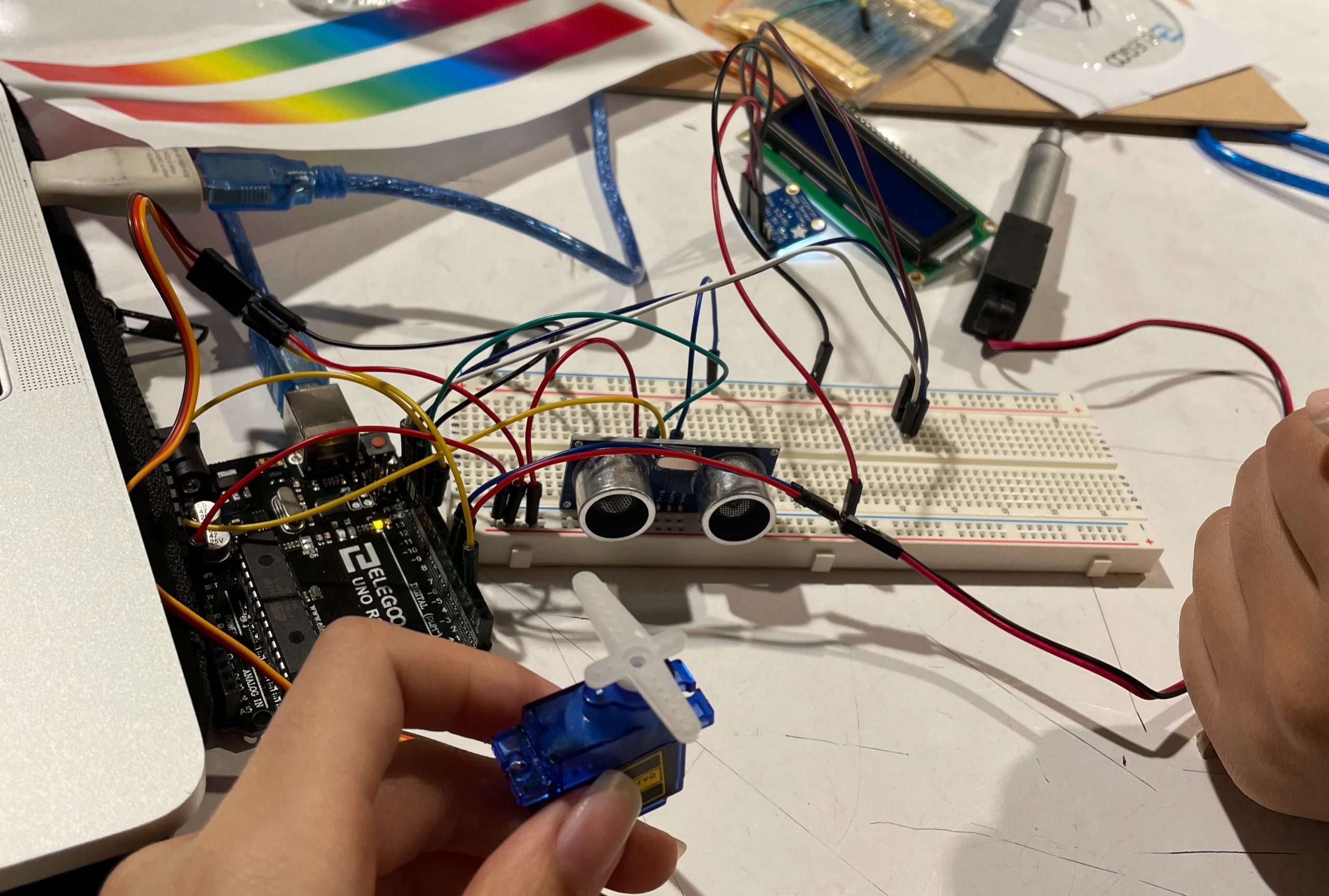
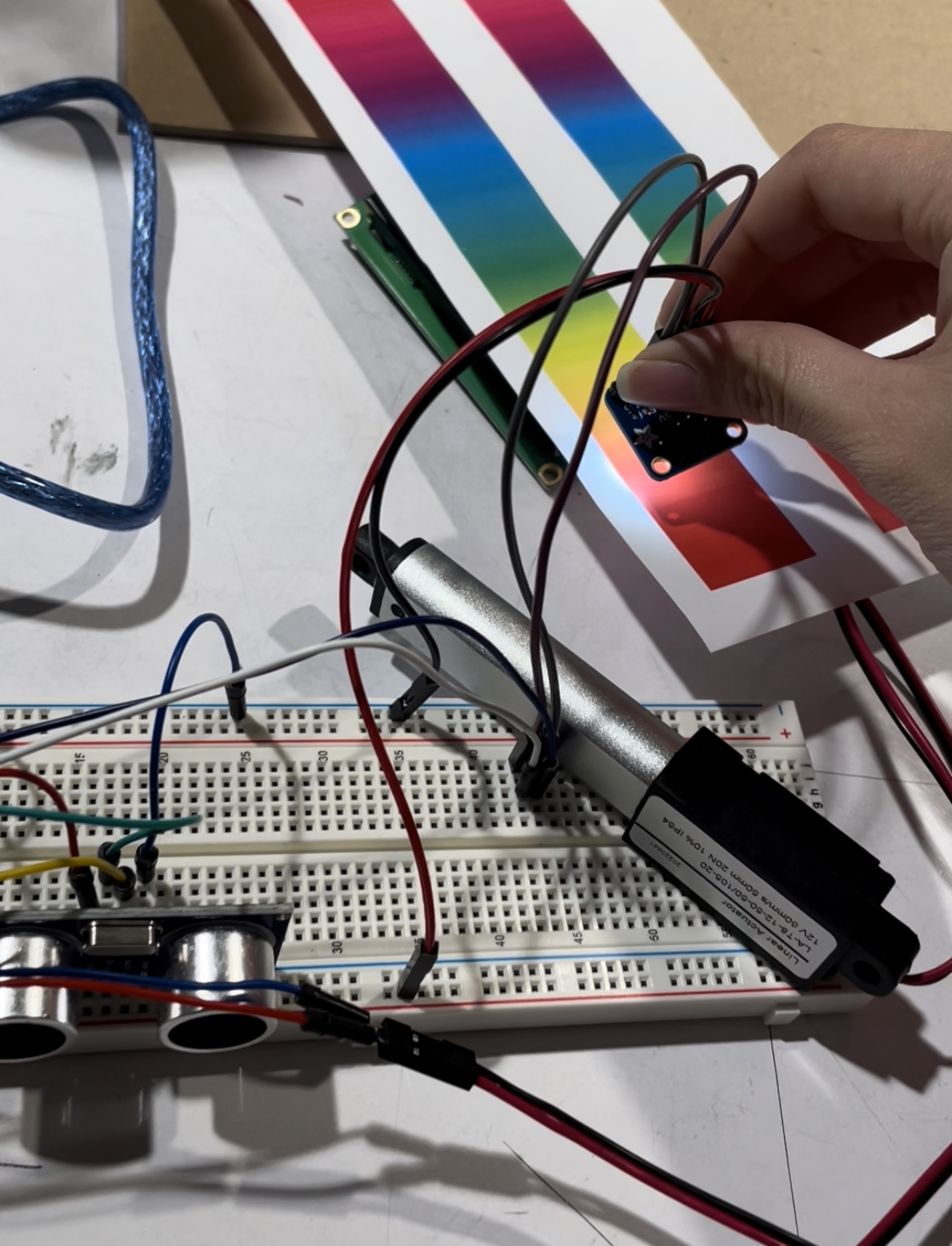
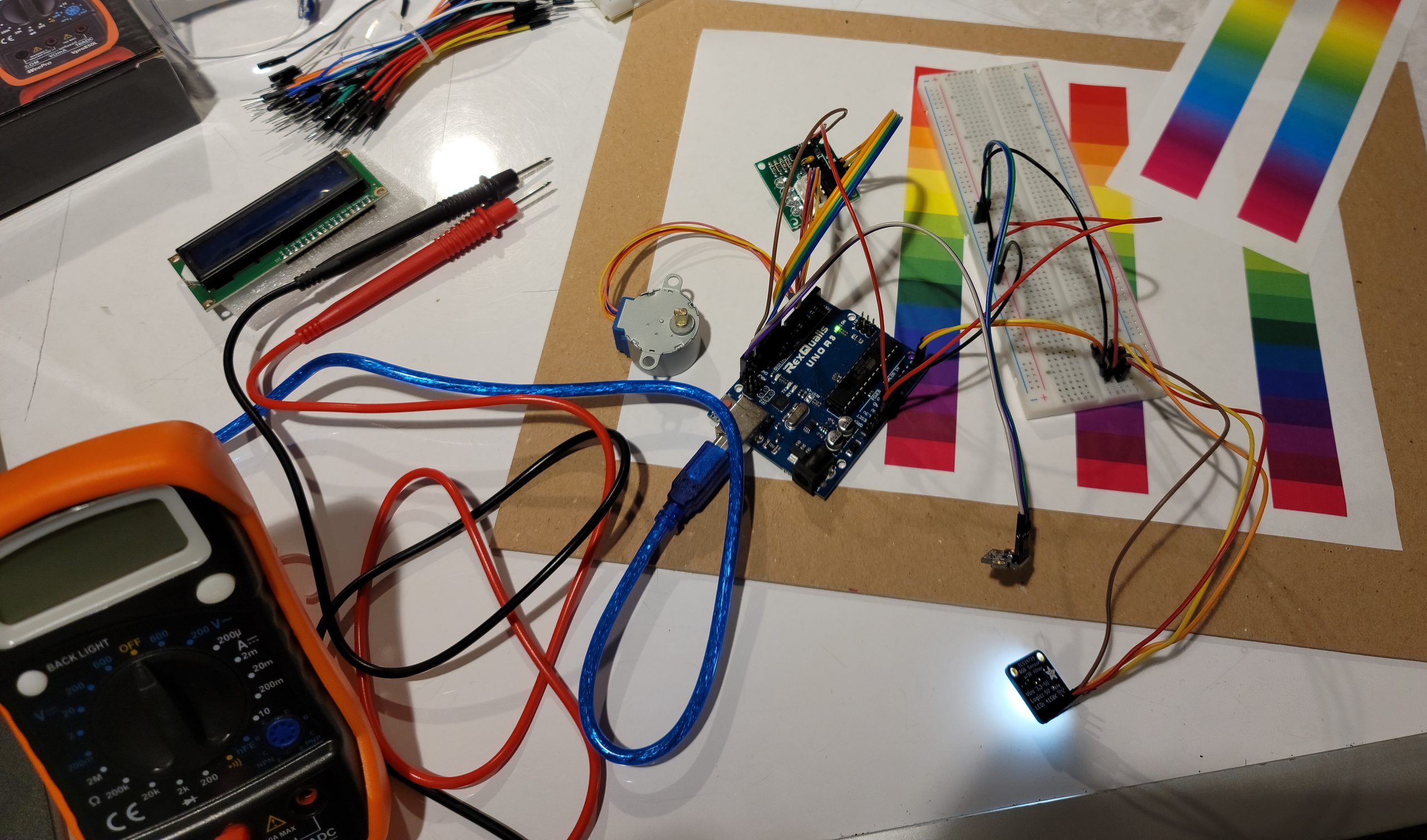
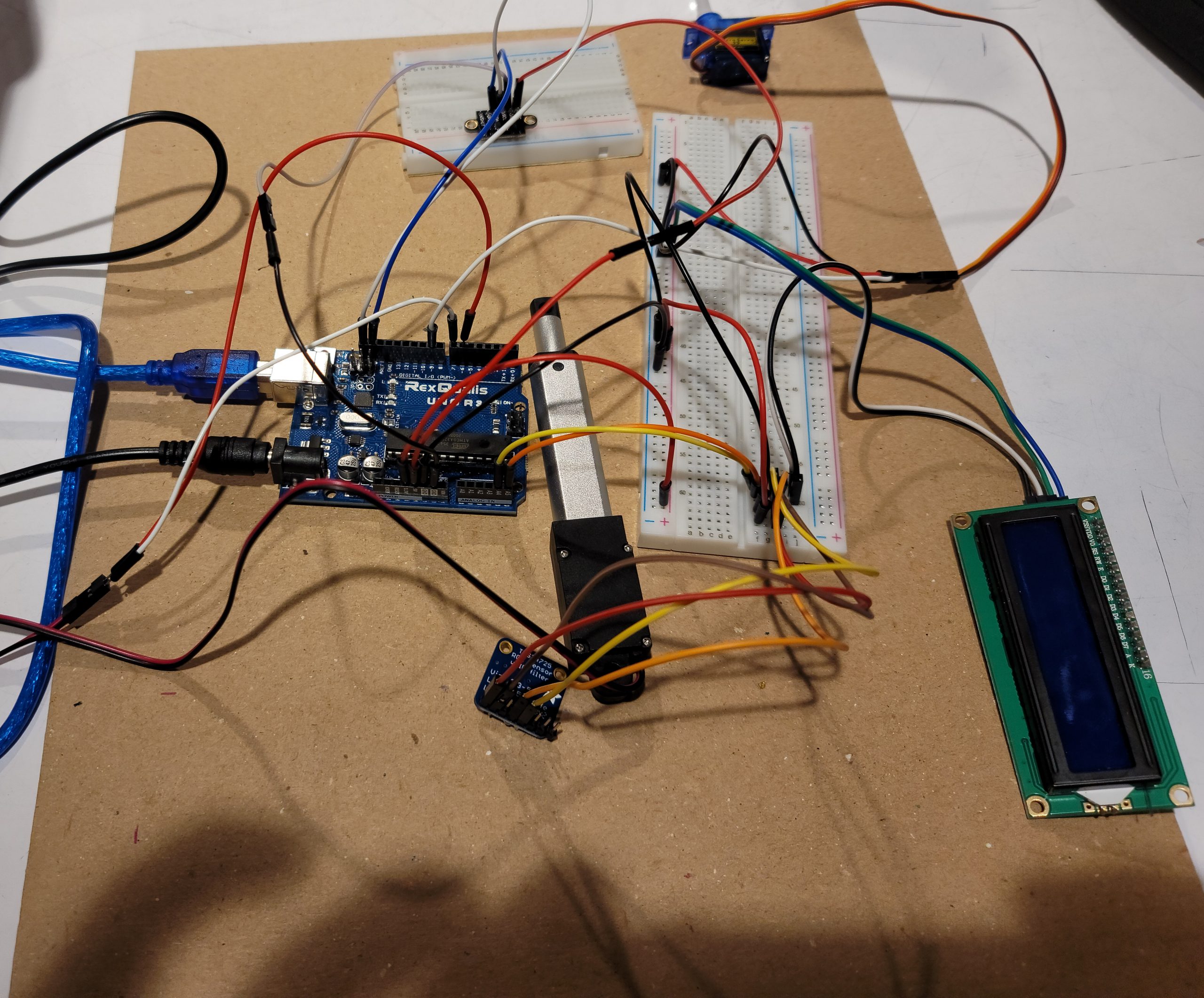
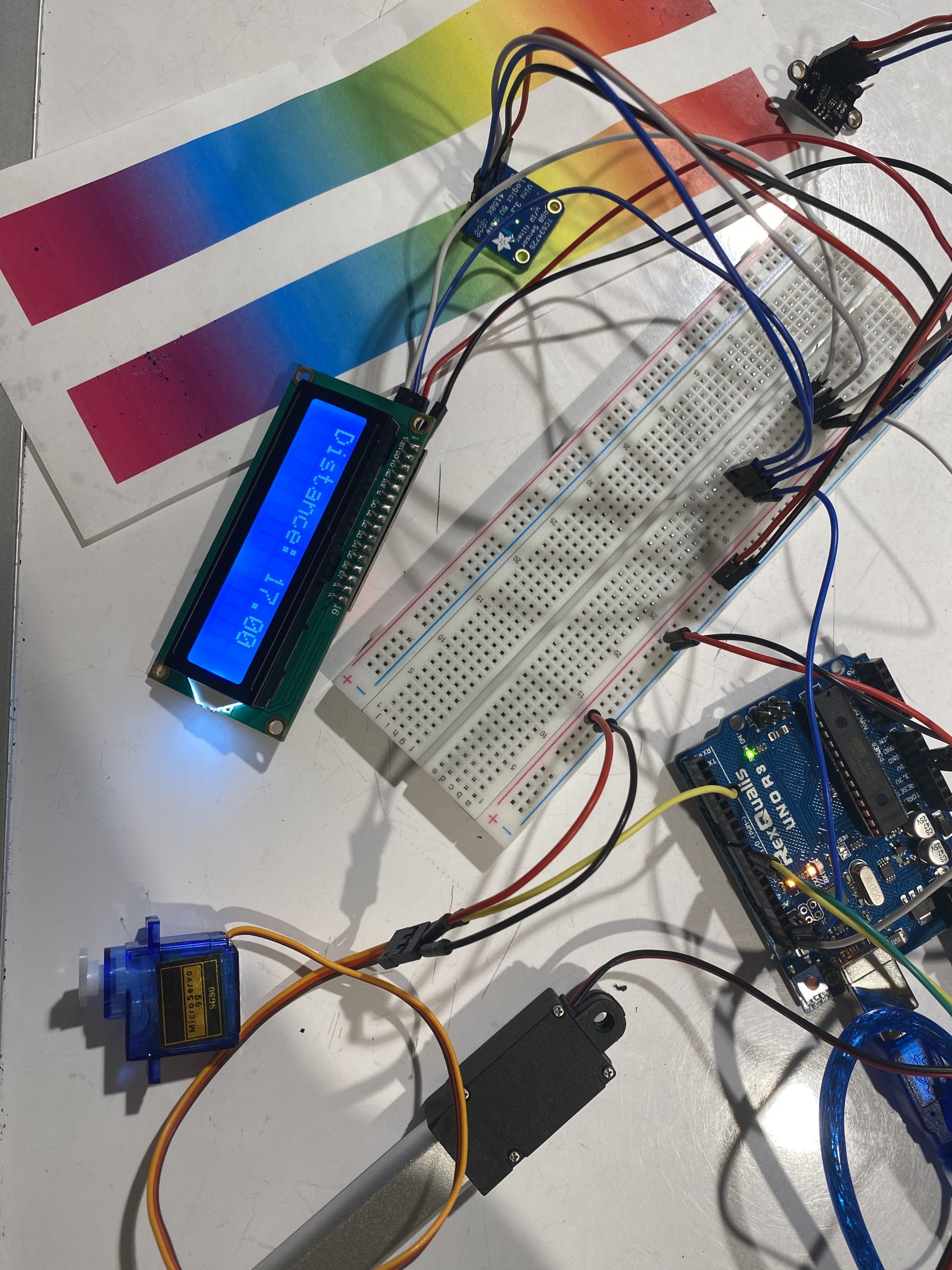
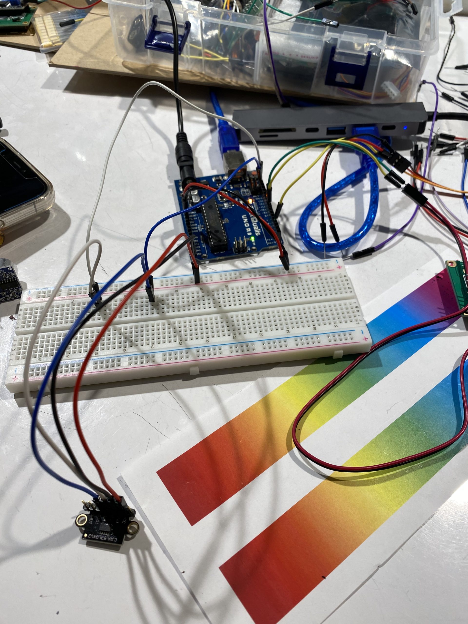
Our double transducer involves the following components: an RGB sensor, a linear actuator, a VL53L0X distance sensor, a servo motor, LCD, and an Arduino Uno. The RGB sensor reads the RGB values of a printed color off of a given gradient sheet. These values are then used to calculate the respective hue (HSV) value for said color. From here, the hue value (range 0 – 360) is mapped to the time the linear actuator extends (0 – 3 seconds for full range of motion). The extension of the linear actuator is read as a change in distance by the VL53L0X time of flight distance sensor. The range of the linear actuators extension is zero to two inches, so the time of flight sensor reads a range of zero to two inches as well (approximately 0 – 50 millimeters). This distance is then mapped to the servo motor’s rotation (with a range of 0 – 90°). The LCD display shows all the aforementioned outputs as mapped to a 0 – 99 range.
Final Double Transducers
Elise’s Double Transducer
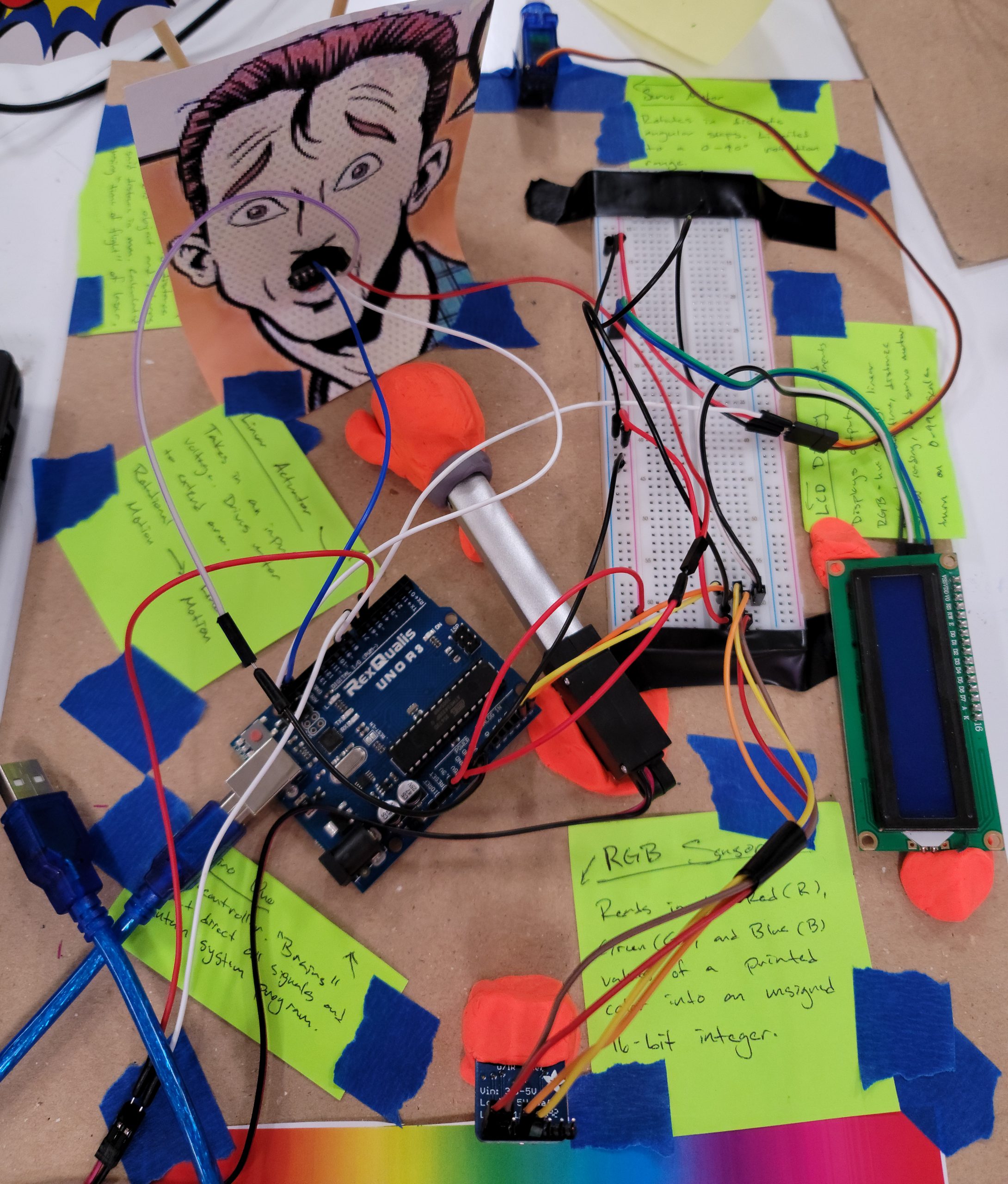
Remy’s Double Transducer
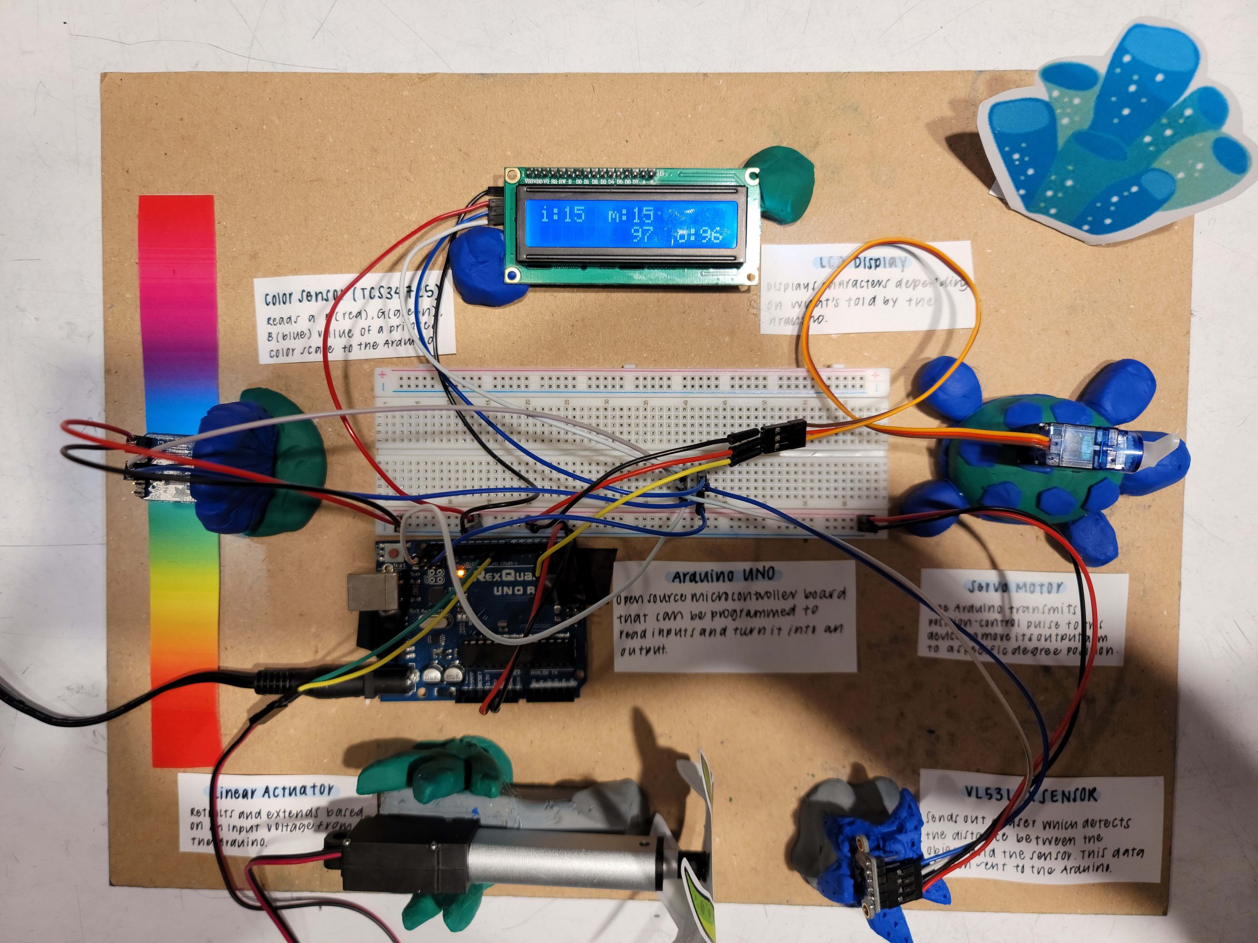
Sharon’s Double Transducer
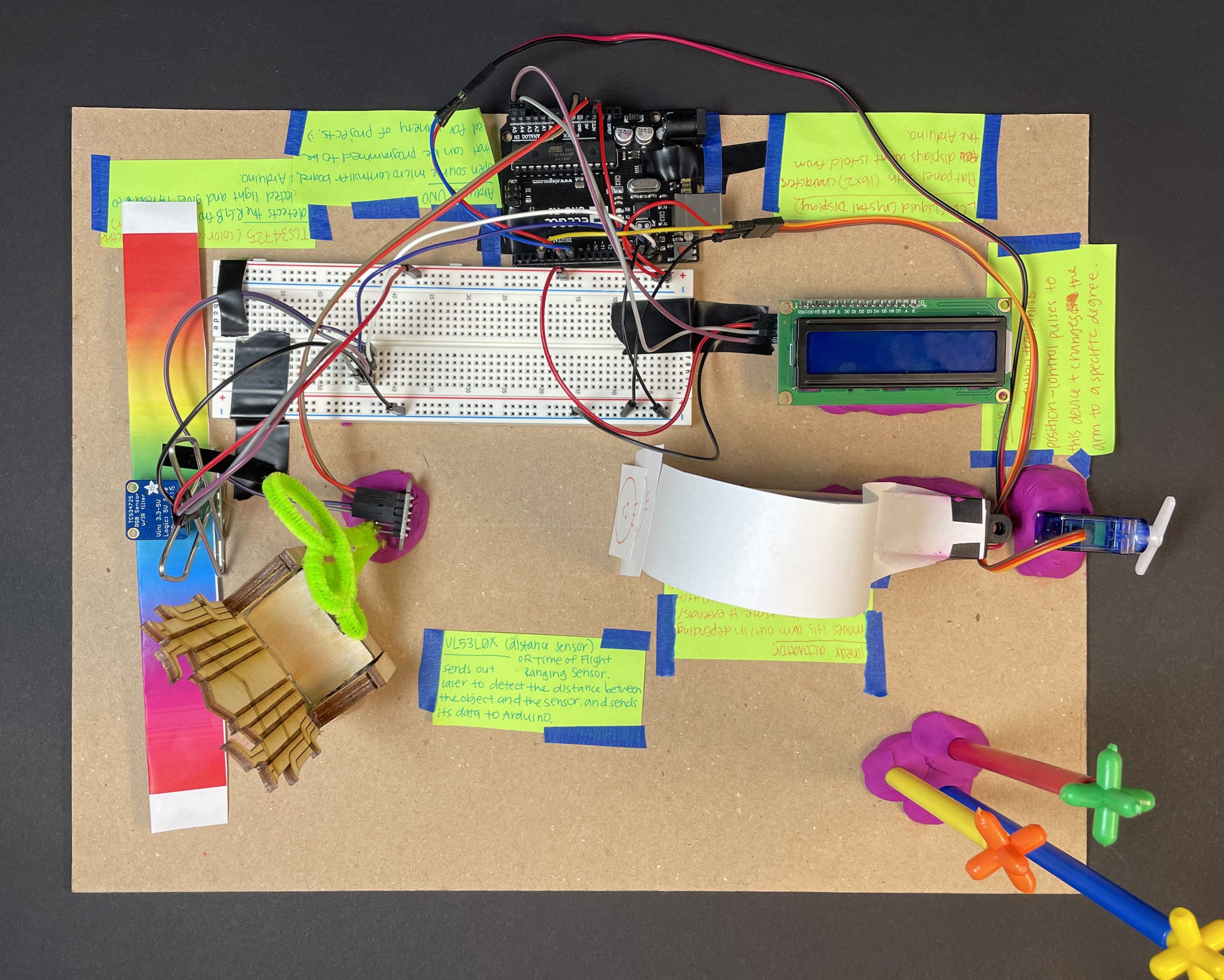
Sarah’s Double Transducer
Detail Photos
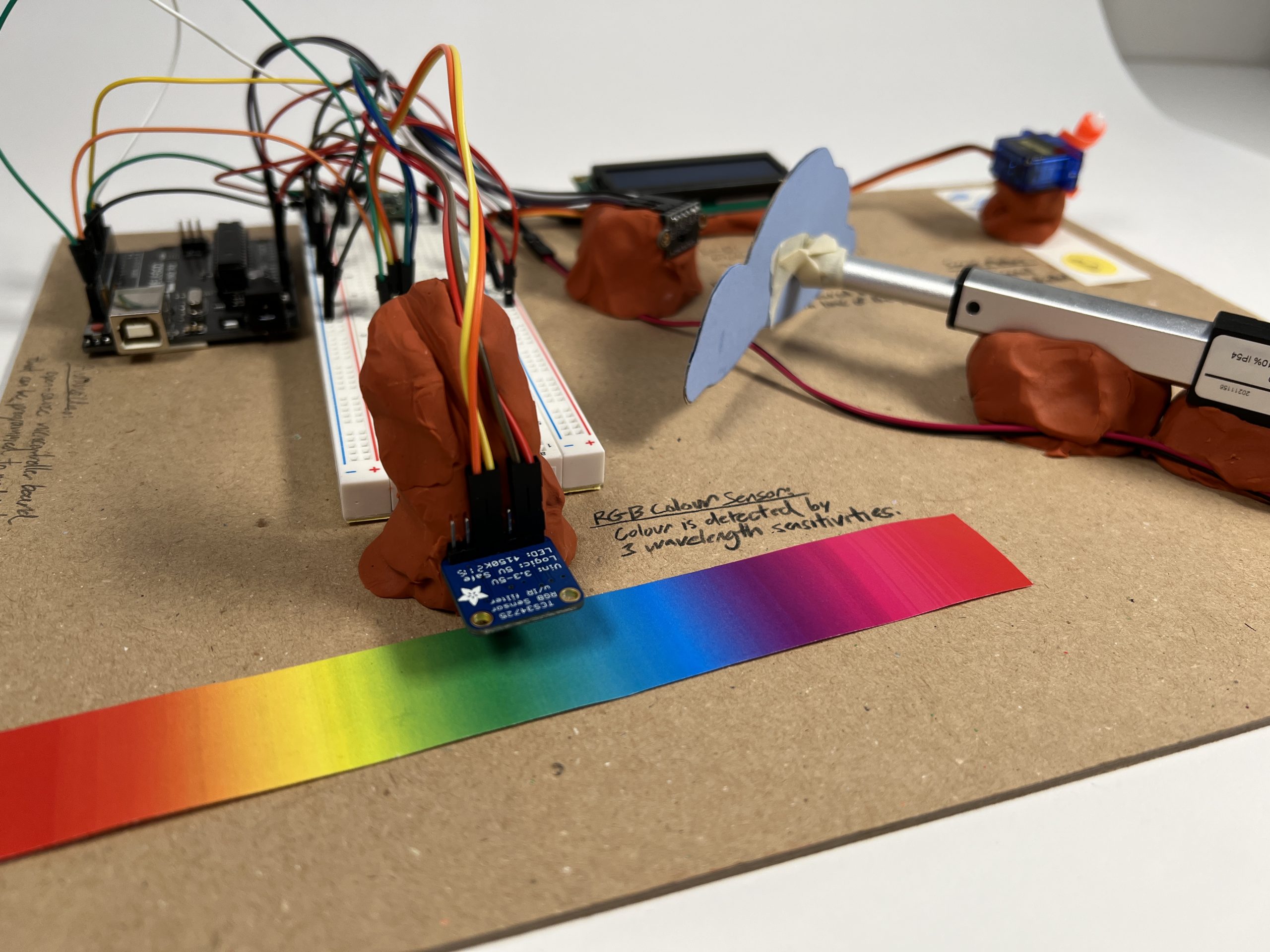
Clay is used to prop up the different parts of the double transducer, including suspending the initial color sensor. (Elise)
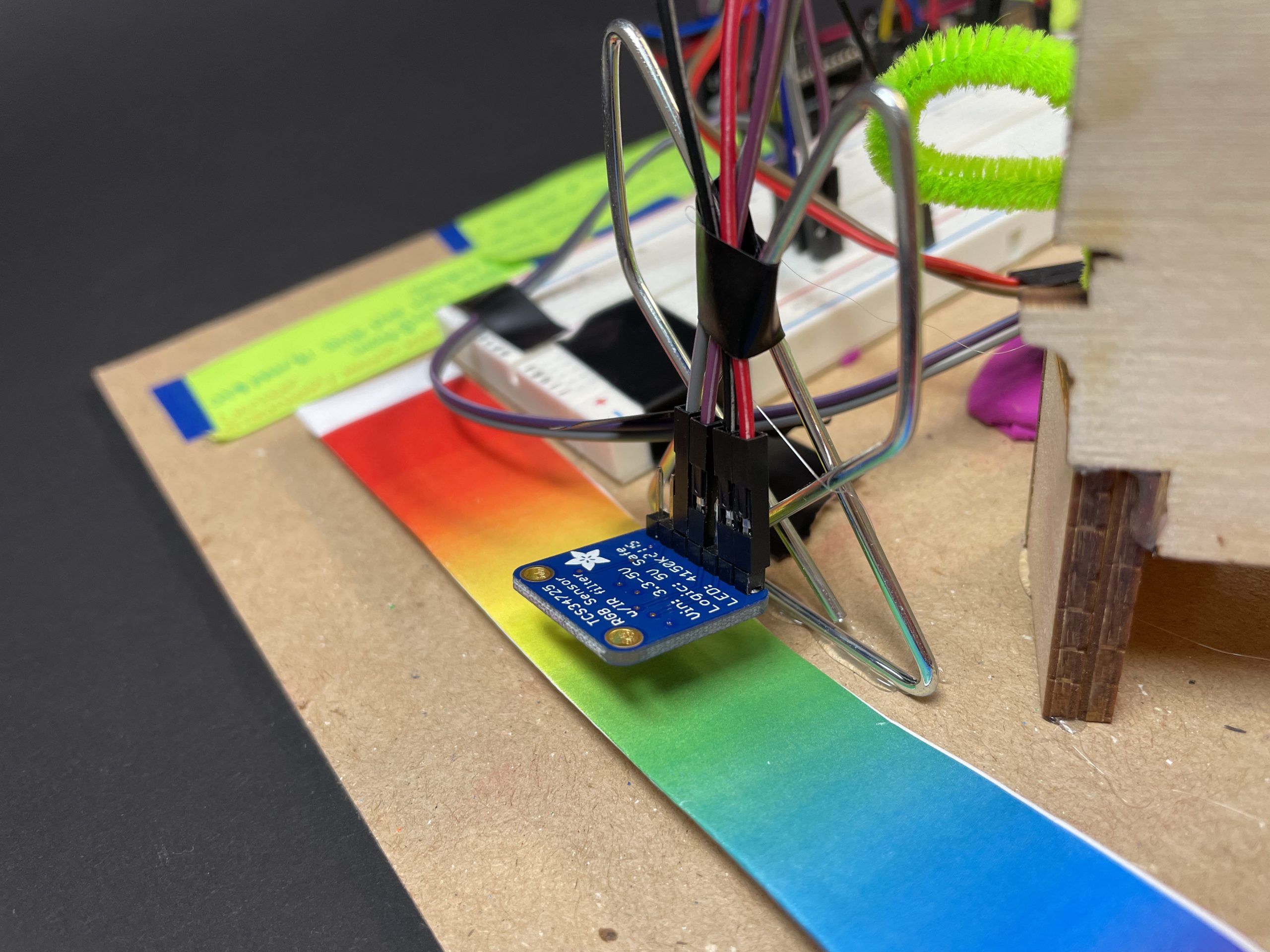
The tcs34725 color sensor is propped up by an inch, and the color strip is removable (Sarah).
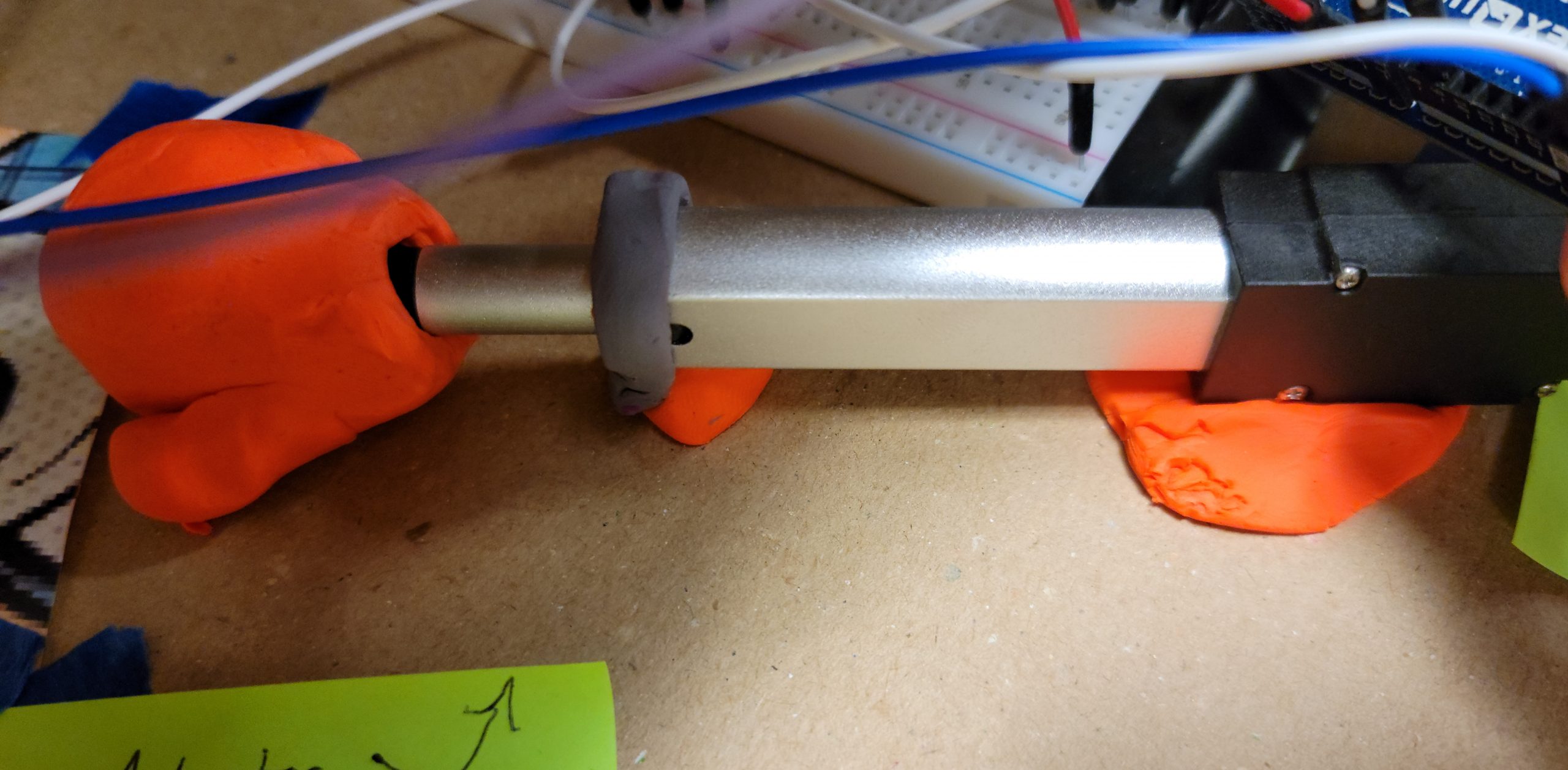
The linear actuator is responsible for driving its piston at a distance dependent on the color read by the RGB sensor (Remington).
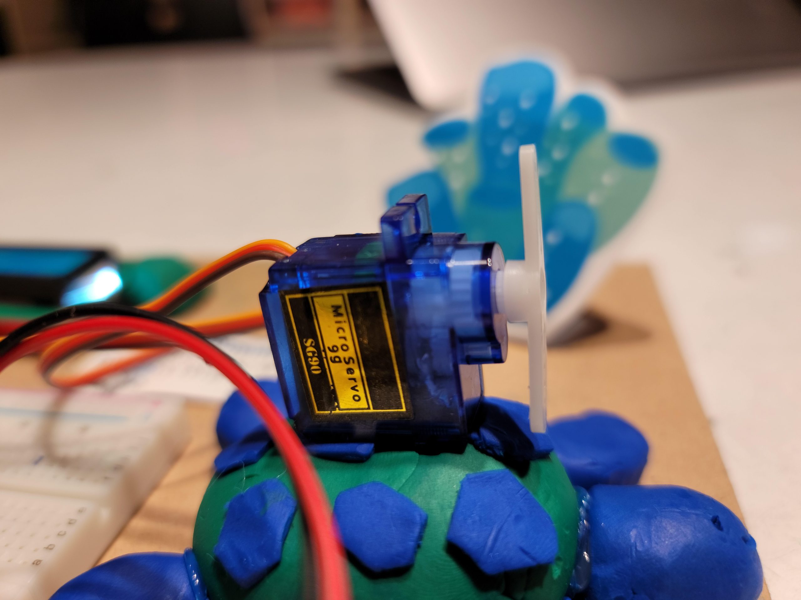
The final output of our double transducer is the servo motor which has a specific rotational position that ranges from 0 to 90 degrees based on the previous inputs (Sharon).
Working Videos
Process Photos
At first, we did not have access to a small linear actuator, so we considered using a rack and pinion attached to a motor (Elise).
We were having some trouble getting the laser distance sensor (VL53L0X) to work initially, but I worked with Zach for a bit to get it working (Elise).
We initially started off with Ultrasonic distance sensors but transferred to VL53L0X laser distance sensors (Sarah).
We tested each part individually first before incorporating them into the bigger system (Sarah).
Attempting to debug the VL53L0X sensor. Using a multimeter to probe the pins to ensure proper connections. The error ended up being the RGB sensor and L0X sensor sharing the same default I2C address (Remington).
Here we swapped the stepper motor (for the rack and pinion system) for a linear actuator to simplify the mechanical process of the system (Remington).
All of the individual parts were able to work together but we were not mapping the values in a range from 0 to 99 or the correct format on our LCD display (Sharon).
Switched from the Ultrasonic Ranger to the VL53L0X Sensor where we realized that our soldering negatively affected the functionality and didn’t give us continuous values in the serial output (Sharon).
Discussion
Despite the simplicity of this double transducer in concept, its execution was harder than expected–especially its functionality. Although there were many late additions to our team, we were able to help each other solve similar problems and catch one another up (in which Sharon is very grateful and appreciative) in order to build four double transducers in a short period of time.
For our input, the color sensor was reading the RGB values of the given color strip because that is how computers perceive color, but we had to convert it to HSV color values, which is how humans perceive color. It was an interesting experience to introduce device the way we perceive color in order to give it a singular value input (hue) to work with the linear actuator.
Another problem we encountered that wasn’t an apparent one to us was the correct and neat soldering of our parts, specifically on the theVL53L0X sensor. This ultimately led to many problems when testing the parts individually as well as together as one entity with the other inputs and outputs. We had to make sure that our VL53L0X distance sensor was facing the right direction and that none of the metals bridged between each other. This trial and error process allowed us to understand how important it was to solder carefully and neatly as well as check our schematics beforehand.
Lastly, mapping the values so that each of the parts works cohesively was a struggle. Because there were multiple values being transferred into the next action and another action after that, it was crucial that we map each value to fit the other components’ range in order to make the board functional. We had to initially test the VL53L0X distance sensor to calculate the distance it reads and limit our range to that, then maps that value to a degree the motor arm should move so that we can visually see its change. Although we got it in the end, it required some calculations and test trials to make the entire system work.
However, overall we were able to get all the aspects working, and our team finished with functional double transducers.
Functional Block Diagram and Electrical Schematic
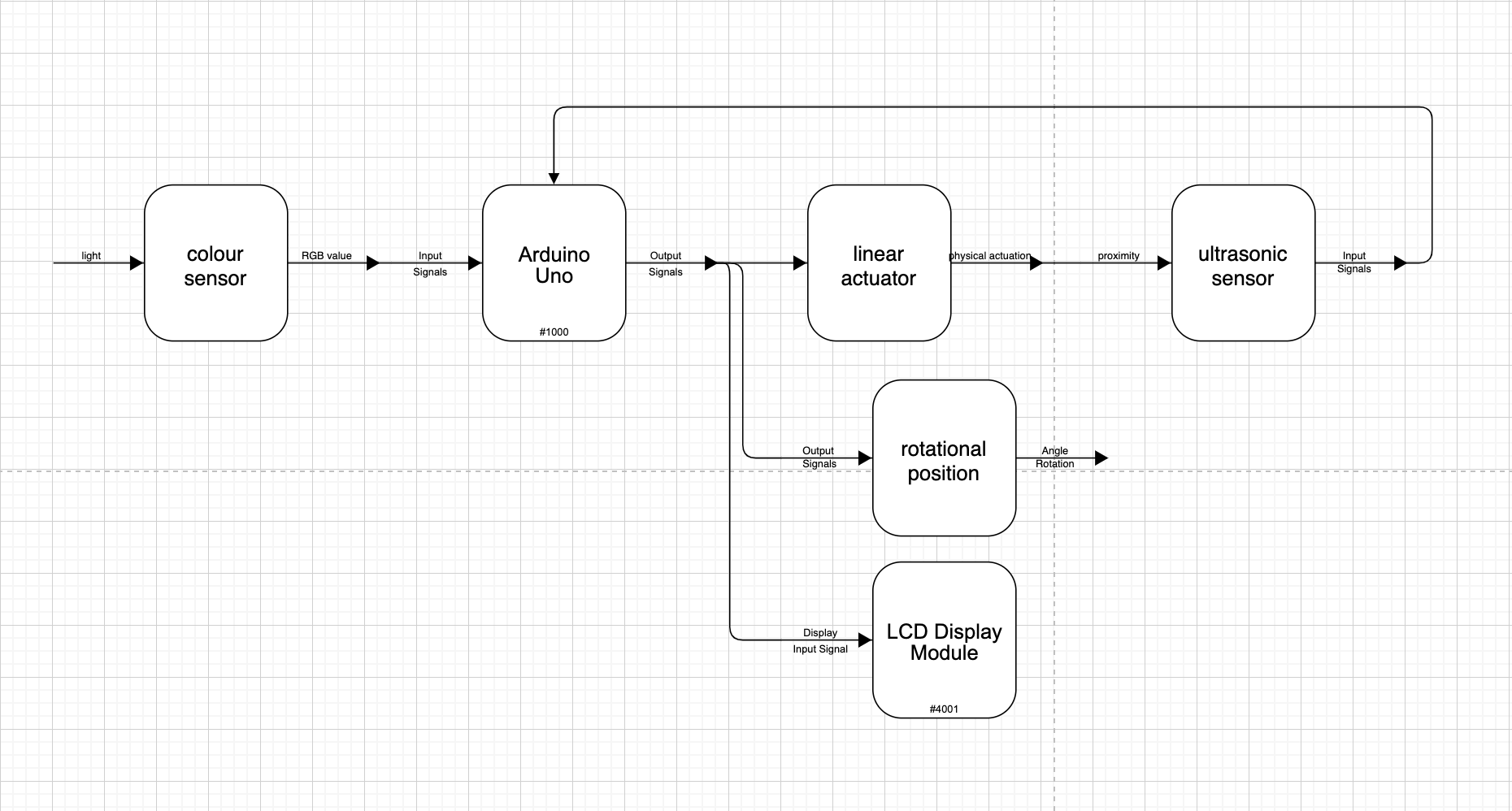
Block Diagram
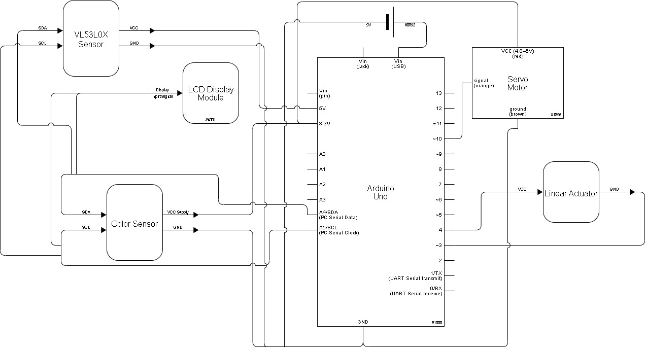
Electrical Schematic
Code
/*
   Double Transducer: From Printed Color to Servo Motor Rotation
   {Sarah Yun, Elise Chapman, Sharon Li, Remington Frank}

   The code below processes and translates an input RGB reading from
   a printed color scale to a servo motor rotation (0 - 90°). It being
   a double transducer, the middle step is a linear actuator that extends
   and has its extension distance then read by a VL53L0x distance sensor.

   Pin Map:
  Pin | role | Description
 ----------------------------------------
   6 | output| VCC input for linear actuator
   7 | input | GND for linear actuator
  9  | output| Servo motor middle pin
 SCL | input | SCL pin on VL53L0X sensor
 SDA | input | SDA pin on VL53L0X sensor
  A4 | input | SCL pin on I2C LCD display
  A5 | input | SDA pin on I2C LCD display
  5V | output| VL53L0X sensor power
3.3V | output| Power for remaining components
 GND | input | Ground for all components

   RGB Sensor code sourced from the Adafruit TCS34725
   RGB Sensor example code. For further reference,
   refer to the following:

   https://learn.adafruit.com/adafruit-color-sensors/arduino-code

   VL53L0X sensor code is sourced from the Pololu library. This
   library can be found at the following link:

   https://github.com/pololu/vl53l0x-arduino

   Conversion from RGB to HSV values makes use of an algorithm sourced from:

   https://www.rapidtables.com/convert/color/rgb-to-hsv.html

   This has also been done as shown on the GeeksForGeeks site, which our
   code is very akin (identical) to:

   https://www.geeksforgeeks.org/program-change-rgb-color-model-hsv-color-model/
   All credit is due to the above for the respective sections mentioned.

*/

#include <Wire.h>
#include "Adafruit_TCS34725.h"
#include <Servo.h>
#include <LiquidCrystal_I2C.h>
#include <Wire.h>
#include <VL53L0X.h>

VL53L0X sensor;
/* Initialise with default values (int time = 2.4ms, gain = 1x) */
// Adafruit_TCS34725 tcs = Adafruit_TCS34725();

/* Initialise with specific int time and gain values */
Adafruit_TCS34725 tcs = Adafruit_TCS34725(TCS34725_INTEGRATIONTIME_614MS, TCS34725_GAIN_1X);
Servo myServo;
LiquidCrystal_I2C lcd(0x27, 16, 2);

const int SERV = 9;
int FWD = 6;
int REV = 7;

// Initialize evaluation criteria and other values

double hue, saturation, value;
long duration;
double distance;

float prevRunTime;
float runTime;

unsigned long trueTime;
unsigned long currTime;
unsigned long delayTime;
unsigned long printTime;

int turn;
int prevTurn;
int counter;

int h_print;
int la_print;
int dist_print;
int s_print;

bool printer = 1;

void setup(void) {
  Serial.begin(115200);
  Wire.begin();

  lcd.begin();
  lcd.backlight();

  bool start = 1;

  // Begin color sensing sensor
  if (tcs.begin()) {
    Serial.println("Found sensor");
  } else {
    Serial.println("No TCS34725 found ... check your connections");
    while (1);
  }

  // Initilize pin modes
  pinMode(trigPin, OUTPUT);
  pinMode(echoPin, INPUT);

  pinMode(FWD, OUTPUT);
  pinMode(REV, OUTPUT);

  digitalWrite(FWD, LOW);
  digitalWrite(REV, HIGH);
  delay(3000);

  myServo.attach(SERV);

  sensor.setAddress(0x52);
  sensor.setTimeout(500);
  if (!sensor.init())
  {
    Serial.println("Failed to detect and initialize sensor!");
    while (1) {}
  }

  // Start continuous back-to-back mode (take readings as
  // fast as possible).  To use continuous timed mode
  // instead, provide a desired inter-measurement period in
  // ms (e.g. sensor.startContinuous(100)).
  sensor.startContinuous();
}

void loop(void) {
  trueTime = millis();

  uint16_t r, g, b, c, colorTemp, lux;

  // Gather various color data from RGB sensor
  tcs.getRawData(&r, &g, &b, &c);
  // colorTemp = tcs.calculateColorTemperature(r, g, b);
  colorTemp = tcs.calculateColorTemperature_dn40(r, g, b, c);
  lux = tcs.calculateLux(r, g, b);

  Serial.print("Color Temp: "); Serial.print(colorTemp, DEC); Serial.print(" K - ");
  Serial.print("Lux: "); Serial.print(lux, DEC); Serial.print(" - ");
  Serial.print("R: "); Serial.print(r, DEC); Serial.print(" ");
  Serial.print("G: "); Serial.print(g, DEC); Serial.print(" ");
  Serial.print("B: "); Serial.print(b, DEC); Serial.print(" ");
  Serial.print("C: "); Serial.print(c, DEC); Serial.print(" ");
  Serial.println(" ");

  // RGB to HSV conversion
  double rWeight = r / 65535.0;
  double gWeight = g / 65535.0;
  double bWeight = b / 65535.0;

  Serial.println("Red Weight: "); Serial.print(rWeight); Serial.println(" ");

  // RGB to HSV algorithm
  double cmax = max(rWeight, max(gWeight, bWeight)); // maximum of r, g, b
  double cmin = min(rWeight, min(gWeight, bWeight)); // minimum of r, g, b
  double diff = cmax - cmin; // diff of cmax and cmin.
  double h = -1;

  // if cmax and cmax are equal then h = 0
  if (cmax == cmin) {
    h = 0;
  }

  // if cmax equal r then compute h
  else if (cmax == rWeight) {
    h = fmod(60 * ((gWeight - bWeight) / diff) + 360, 360);
  }

  // if cmax equal g then compute h
  else if (cmax == gWeight) {
    h = fmod(60 * ((bWeight - rWeight) / diff) + 120, 360);
  }

  // if cmax equal b then compute h
  else if (cmax == bWeight) {
    h = fmod(60 * ((rWeight - gWeight) / diff) + 240, 360);
  }

  Serial.println(" ");
  Serial.print("Hue: "); Serial.print(h); Serial.print(" ");
  Serial.println(" ");
  //--------------------------------------------------------------------------------------------------------

  // Map Hue value to linear actuator distance extended. Linear actuator has an operating time
  // range of 0 to 3 seconds, hence the mapping to 0 to 3000 milliseconds.

  runTime = map(h, 0, 360, 0, 3000);

  if(runTime > prevRunTime) {
    digitalWrite(FWD, HIGH);
    digitalWrite(REV, LOW);
    delay(runTime - prevRunTime);
  }
  else if (runTime < prevRunTime){
    digitalWrite(FWD, LOW);
    digitalWrite(REV, HIGH);
    delay(prevRunTime - runTime);
  }

  prevRunTime = runTime;
  digitalWrite(FWD, LOW);
  digitalWrite(REV, LOW);

  //--------------------------------------------------------------------------------------------------------
  // Read distance extended of linear actuator by the time of flight sensor

  distance = sensor.readRangeContinuousMillimeters() - 63;
  Serial.print(distance);
  if (sensor.timeoutOccurred()) { Serial.print(" TIMEOUT"); }

  Serial.println();
  //--------------------------------------------------------------------------------------------------------
  // Map distance detected into 90° rotation of servo

  turn = map(distance, 0, 50, 0, 90);
  if(turn > 90) turn = 90;
  myServo.write(turn);

  //--------------------------------------------------------------------------------------------------------
  // Print inputs and outputs to LCD display

  h_print = map(h, 0, 360, 0, 99);
  la_print = map(runTime, 0, 3000, 0, 99);
  dist_print = map(distance, 0, 50, 0, 99);
  s_print = map(turn, 0, 90, 0, 99);

  // Update the LCD display every 250 milliseconds (4 times per second)
  if(trueTime - printTime >= 250){
    lcd.home();
    lcd.print(String("i:") + String(int(h_print)));
    lcd.setCursor(6,0);
    lcd.print(String("m:") + String(la_print));
    lcd.setCursor(8, 1);
    lcd.print(String(dist_print));
    lcd.setCursor(12, 1);
    lcd.print(String("o:") + String(s_print));
  }
}