Ethan Hu & Francesca Menendez
Simple Narrative Description:
When a knob is turned, a fan blows wind faster or slower accordingly, which then activates an airflow sensor. This then makes an index card move up and down.
Technical Description:
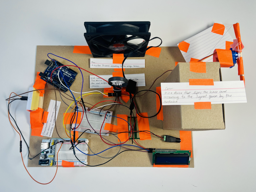
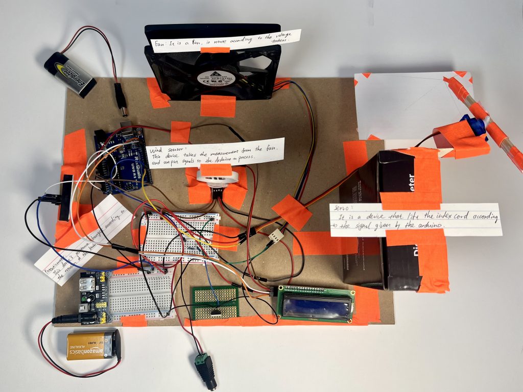
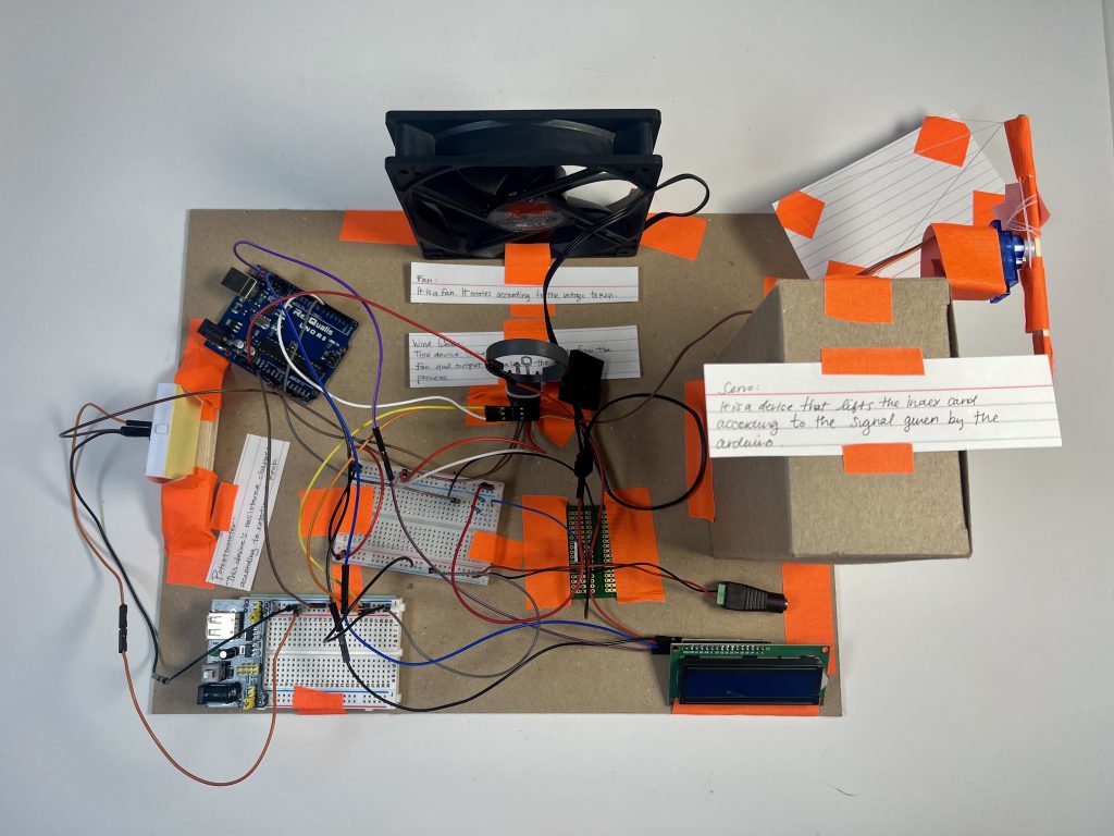
Our double transducer consists of a potentiometer, DC fan, servo motor, wind sensor, and an Arduino to change the height of an index card according to the rotational position of the potentiometer. To achieve this, we first took the analog input of the potentiometer and translated that into a PWM signal which was then sent to a MOSFET that controls the RPM of the fan. Placed in front of the fan, we had our wind sensor taking measurements of the wind speed created by the fan, which was then processed through a series of calculations to determine an output value to the servo motor that then moves the index card vertically.
Final Double Transducers:
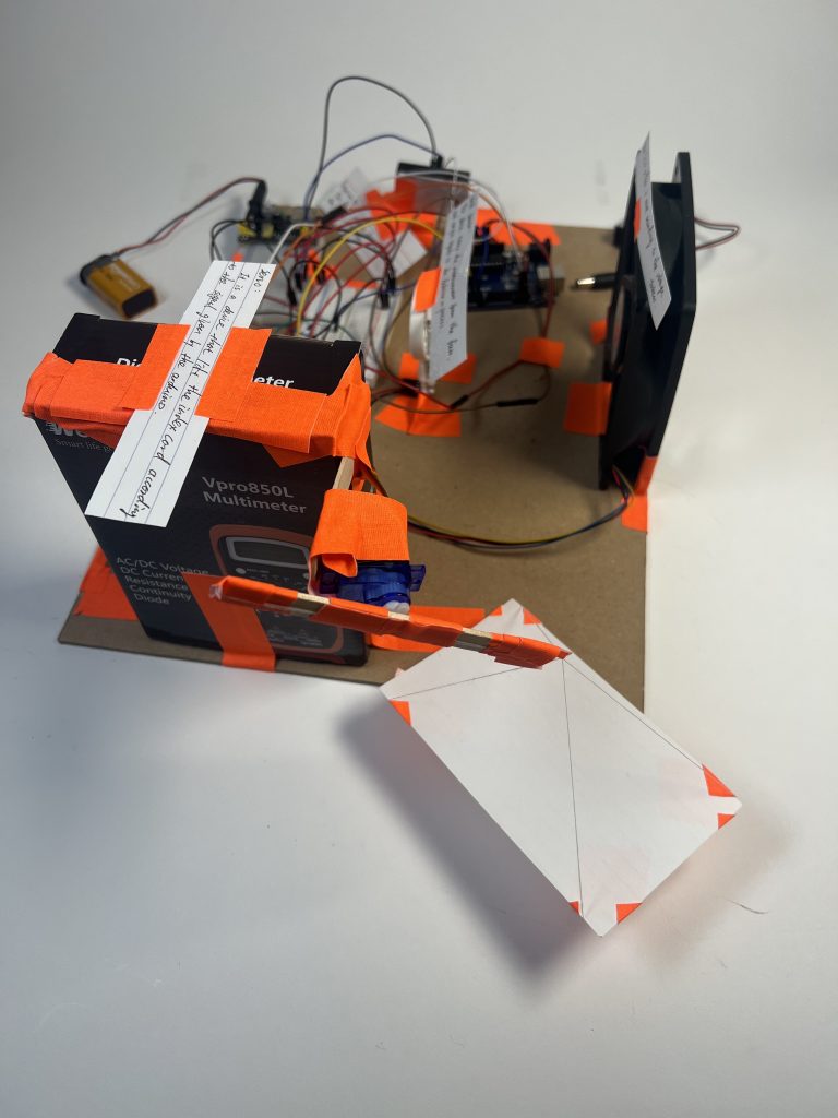
Board 1
Board 2
Detailed Photos:
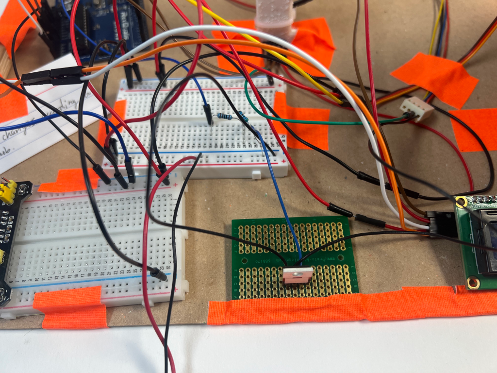
MOSFET + Soldering
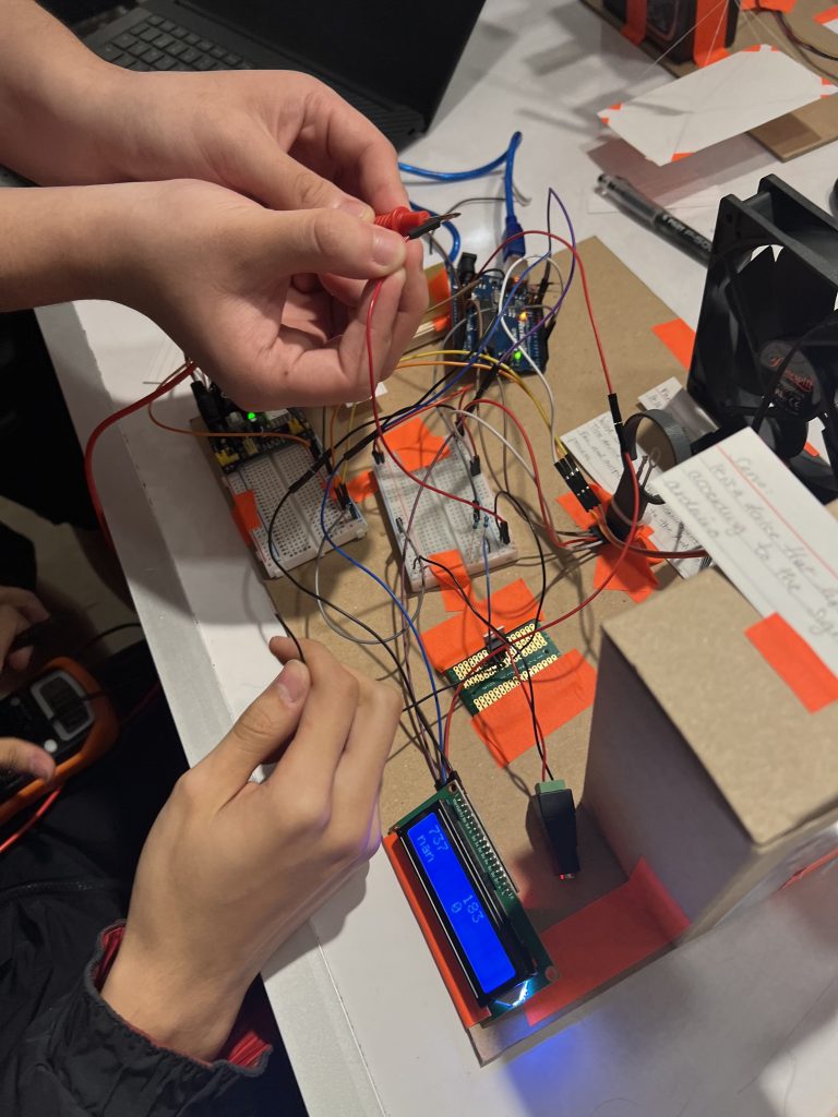
Moving the Index Card using Servo Motor

Fan + Airflow Sensor
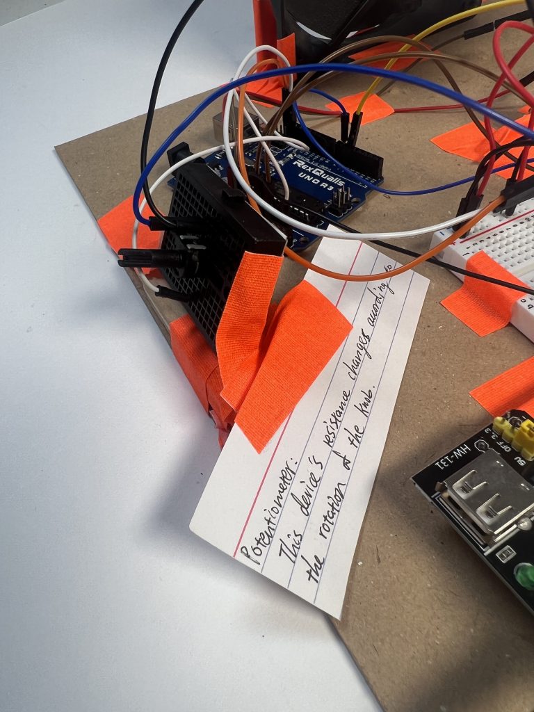
Potentiometer Input
Discussion
The easiest part of our project was coming up with the idea. Using the requirements given to us – rotational position to the movement of an index card, we thought it would be interesting – albeit ridiculous – to use a fan blowing wind into a wind sensor (which neither of us had used before) to then make an index card move up and down using a servo motor. Beyond the simple initial ideation, we ran into lots of issues while building that required us to constantly recheck our work and debug, but ultimately worked when added to the chain of devices other students made.
Because we were working with varied voltages – 5V, 12V, 9V – we had to be especially careful when connecting to laptops and adding power. And though we did spend a lot of time testing each part of our device, we still ended up burning one servo motor and having to replace it due to connecting power sources incorrectly. Once we smelled the smoke, we were able to backtrack and fix the issue. However, we still faced a series of issues that continued to be problematic even when presenting our final devices. For example, the potentiometer could only read a specific range of values and if it would go under or over the threshold (500-900), it would completely freeze and only when back in the correct range, would begin working again as expected. Due to this potentiometer issue, we also found that the wind sensor could now only sense wind speed from 4-8 mph) and, because it was integer mapped, it could only move to 5 positions total, making it clunky when moving. However, we were able to fix this problem by multiplying our values by 10 so that, for example, instead of reading 5.5 mph, it can be read as 55, 60, etc. and, because it is an integer, it can be read more easily. Additionally, we faced some challenges in getting the LCD display to work properly, but by going through our code multiple times, we were able to solve the problem, although it still cannot read any value outside of the range created by the potentiometer problem. While we were able to get the first board working mostly as we expected, the second board, due to not testing the MOSFET before soldering it, the soldering might be one reason as to why it is not working as we would like it to.
While we did face a lot of challenges in building our two boards, we spent a lot of time using the multimeter testing different parts of our device and learned a lot about how to deal with issues that may arise in future projects. We especially learned how important it is to check power sources before connecting them so that nothing goes wrong. It was also especially interesting to learn about MOSFET and the possibilities in redirecting different voltages to avoid anything getting too much voltage. If given the opportunity to do this project again, we would take the time to test the MOSFET before soldering to make sure the second board works as planned and, if given time, we would figure out how to solve the potentiometer issue with range. Ultimately, despite the issues, our two devices reflect the time we put into working and reworking most things on the boards.
Process Images
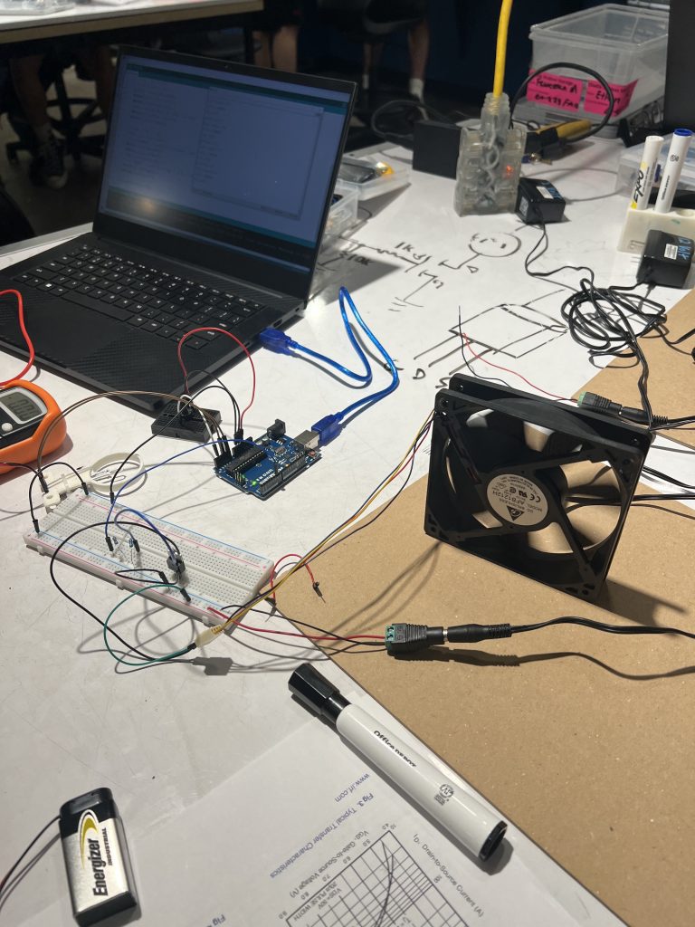
Testing Fan Action
Testing mosFET after Fan Failure

Airflow Sensor Coding
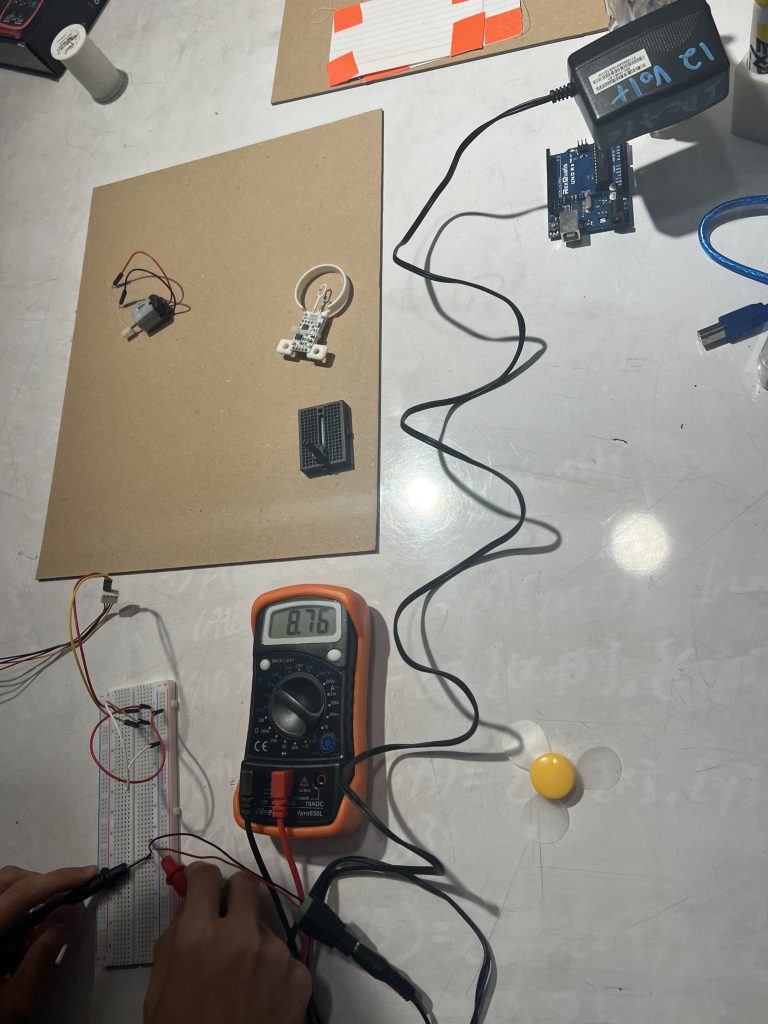
Testing 12V Power Source
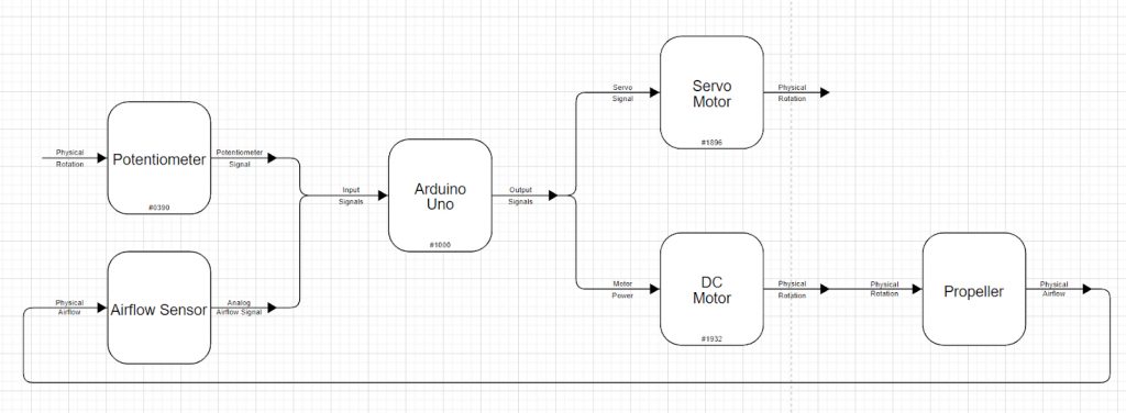
Functional Block Diagram & Schematic
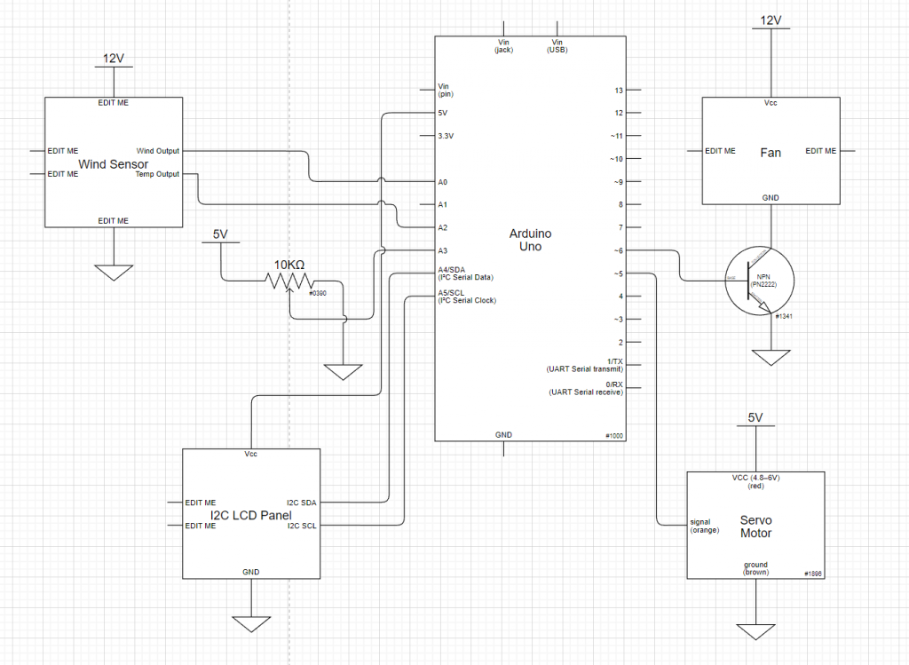
Electrical Schematic
Code
/*Copyright <2022> <Ethan Hu, Francesca Menendez>

Permission is hereby granted, free of charge, to any person obtaining a copy of this software and associated documentation files (the "Software"), to deal in the Software without restriction, including without limitation the rights to use, copy, modify, merge, publish, distribute, sublicense, and/or sell copies of the Software, and to permit persons to whom the Software is furnished to do so, subject to the following conditions:

The above copyright notice and this permission notice shall be included in all copies or substantial portions of the Software.

THE SOFTWARE IS PROVIDED "AS IS", WITHOUT WARRANTY OF ANY KIND, EXPRESS OR IMPLIED, INCLUDING BUT NOT LIMITED TO THE WARRANTIES OF MERCHANTABILITY, FITNESS FOR A PARTICULAR PURPOSE AND NONINFRINGEMENT. IN NO EVENT SHALL THE AUTHORS OR COPYRIGHT HOLDERS BE LIABLE FOR ANY CLAIM, DAMAGES OR OTHER LIABILITY, WHETHER IN AN ACTION OF CONTRACT, TORT OR OTHERWISE, ARISING FROM, OUT OF OR IN CONNECTION WITH THE SOFTWARE OR THE USE OR OTHER DEALINGS IN THE SOFTWARE.

*/

/*Double transducer: Rotational position to the height of an index card.
Ethan Hu & Francesca Menendez


1. Take the input of the potentiometer
2. Output signal to the MOSFET, which will control the fan speed.
3. Take the input from the Wind Sensor.
4. Sent PWM signal to the Servo to adjust the height of the index card.

pin mapping:

Arduino pin / role  /  description
 A0           input    Wind speed input from the wind sensor
 A2           input    Temperature input from the wind sensor
 A5           input    Initial potentiometer input
 6            output   Signal to the MOSFET to control the fan speed
 7            output   PWM signal to the servo moter

*/

#include <Servo.h>
#include <Wire.h>
#include <LiquidCrystal_I2C.h>

LiquidCrystal_I2C screen(0x27, 16, 2);
Servo smotor;

int potVal = 0;
int wind = 0;
int temp = 0;
int fanIn = 0;
int motorIn = 0;

void setup() {
  Serial.begin(9600);
  pinMode(6,OUTPUT);
  smotor.attach(5);
  Wire.begin();
  screen.init();
  screen.backlight();
  screen.home();
  screen.print("It's working!");
  delay(1000);
}

void loop() {
  int time = millis();
  //initial input from the potentiometer
  potVal = analogRead(A5);

  //the input that the fan is taking in
  fanIn = map(potVal, 0, 1023, 0, 255);
  analogWrite(6,fanIn);

  //direct and processed information from the wind sensor
  wind = analogRead(A0);
  float windMPH = pow((((float)wind - 264.0) / 85.6814), 3.36814);

  //input send out to the servo
  motorIn = map(windMPH*10,0,80,0,180);

  //motor set to execute input every quarter of a second
  if (time % 250 == 0){
     smotor.write(motorIn);
  }

  //LCD screen/serial monitor update data every half of a second
  if (time % 250 == 0){
    screen.clear();

    //update input from the potentiometer
    Serial.print("potVal:");
    Serial.println(potVal);
    screen.setCursor(0, 0);
    screen.print(potVal);

    //update the output to the fan
    Serial.print("fan input:");
    Serial.println(fanIn);
    screen.setCursor(8, 0);
    screen.print(fanIn);

    //update the wind speed from the wind sensor
    Serial.print(windMPH);
    Serial.println("MPH");
    screen.setCursor(0, 1);
    screen.print(windMPH);

    //update the output to the servo
    Serial.print("motorIn:");
    Serial.println(motorIn);
    screen.setCursor(8, 1);
    screen.print(motorIn);
  }
}