by Gia Marino and Freda Su
Overall Photos

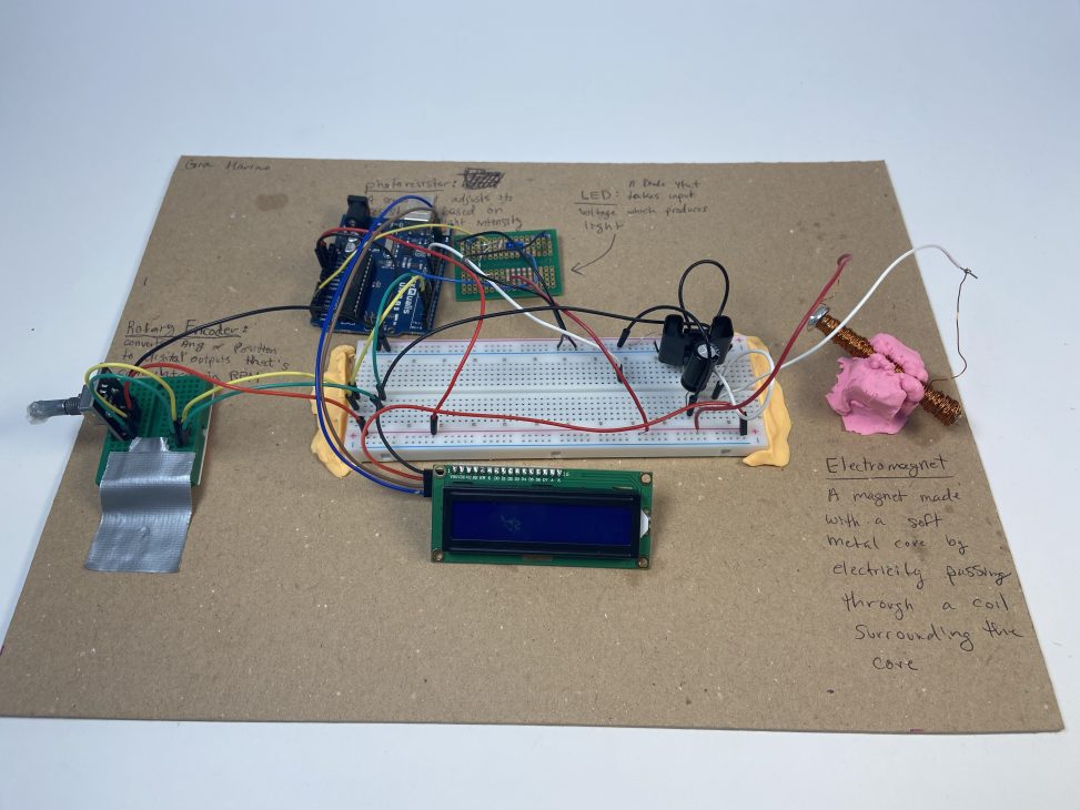
The whole transducer.
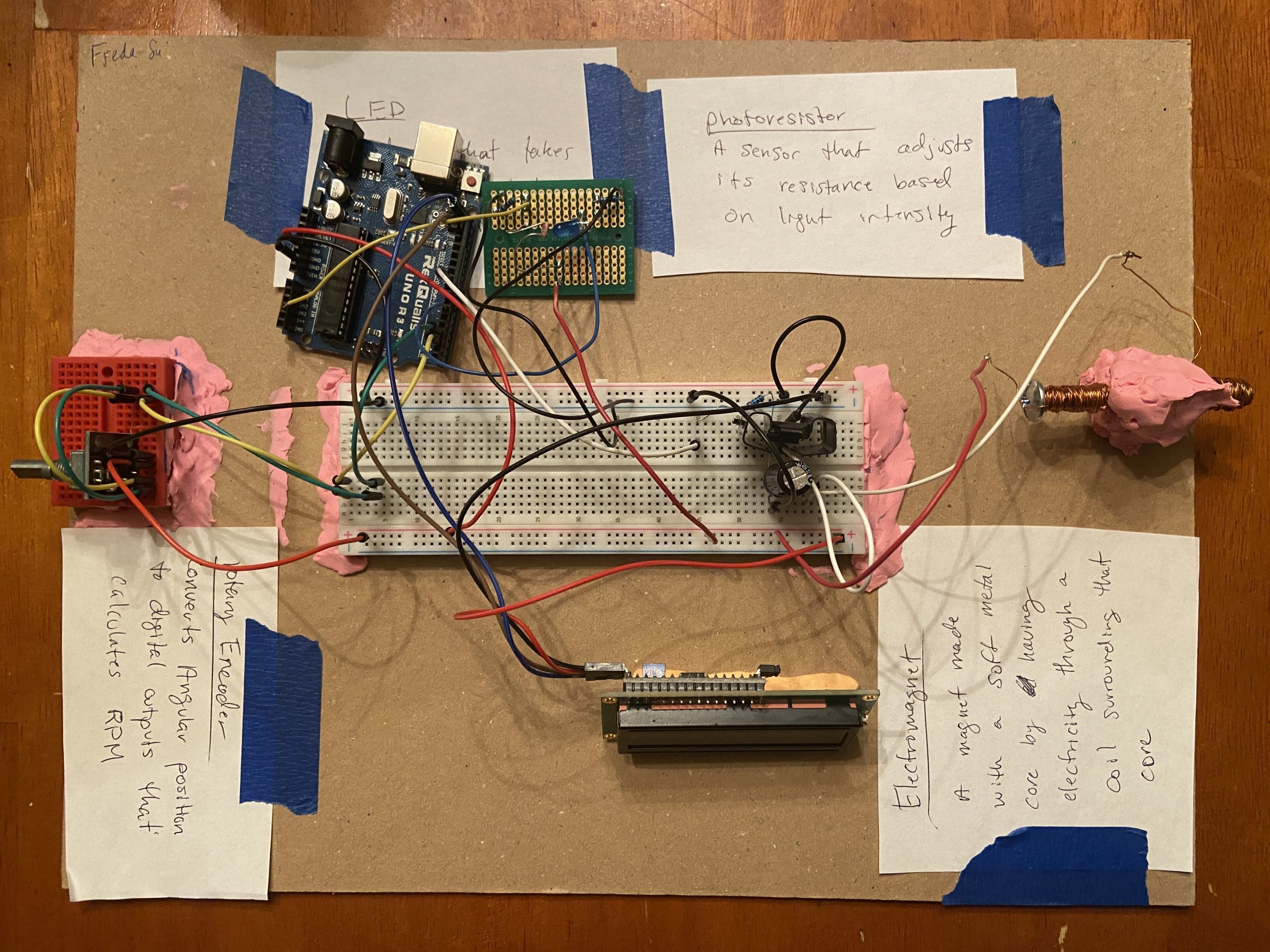
The whole double transducer.
Pictures of Each Part and Videos
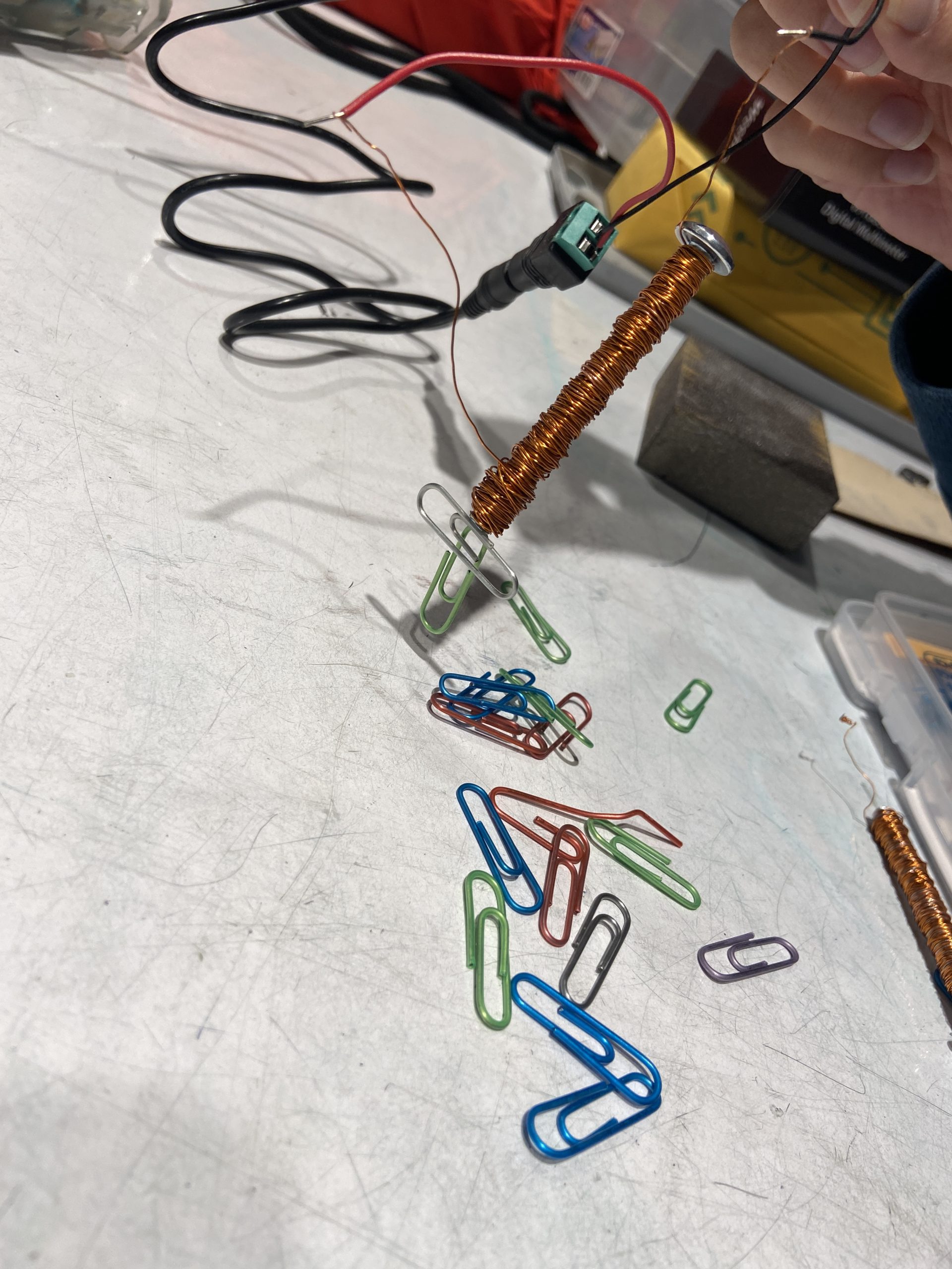
Electromagnet. It creates a magnetic field when power runs through it’s coils
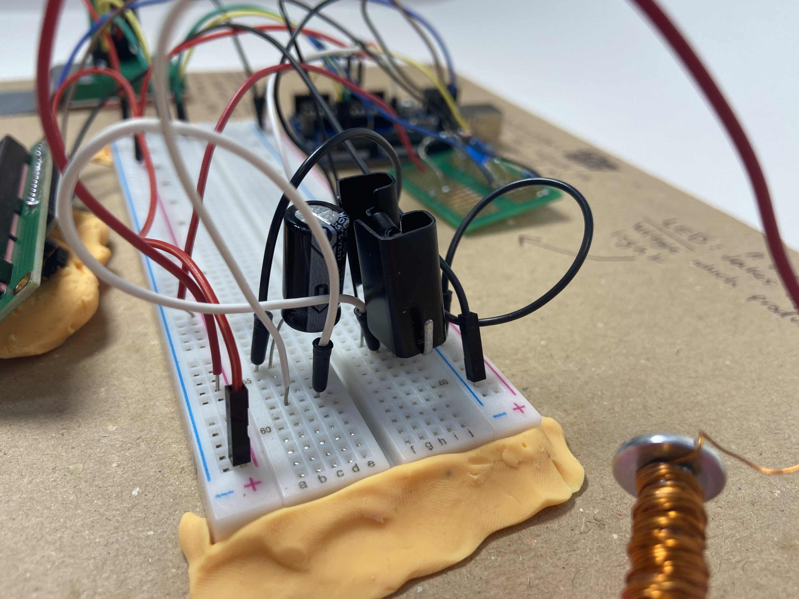
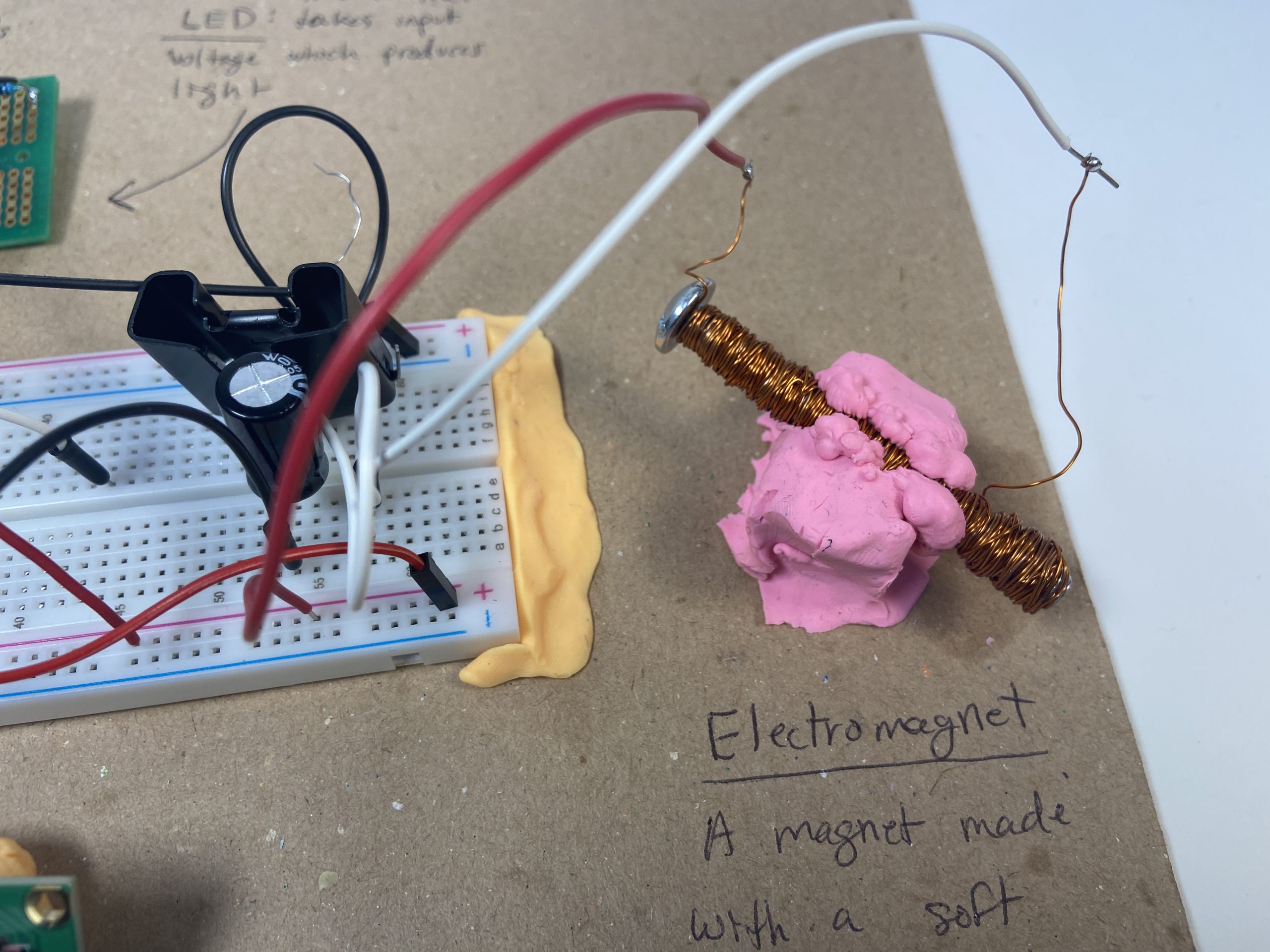
RC circuit and transistor circuit. Smoothes out and amplifies current.
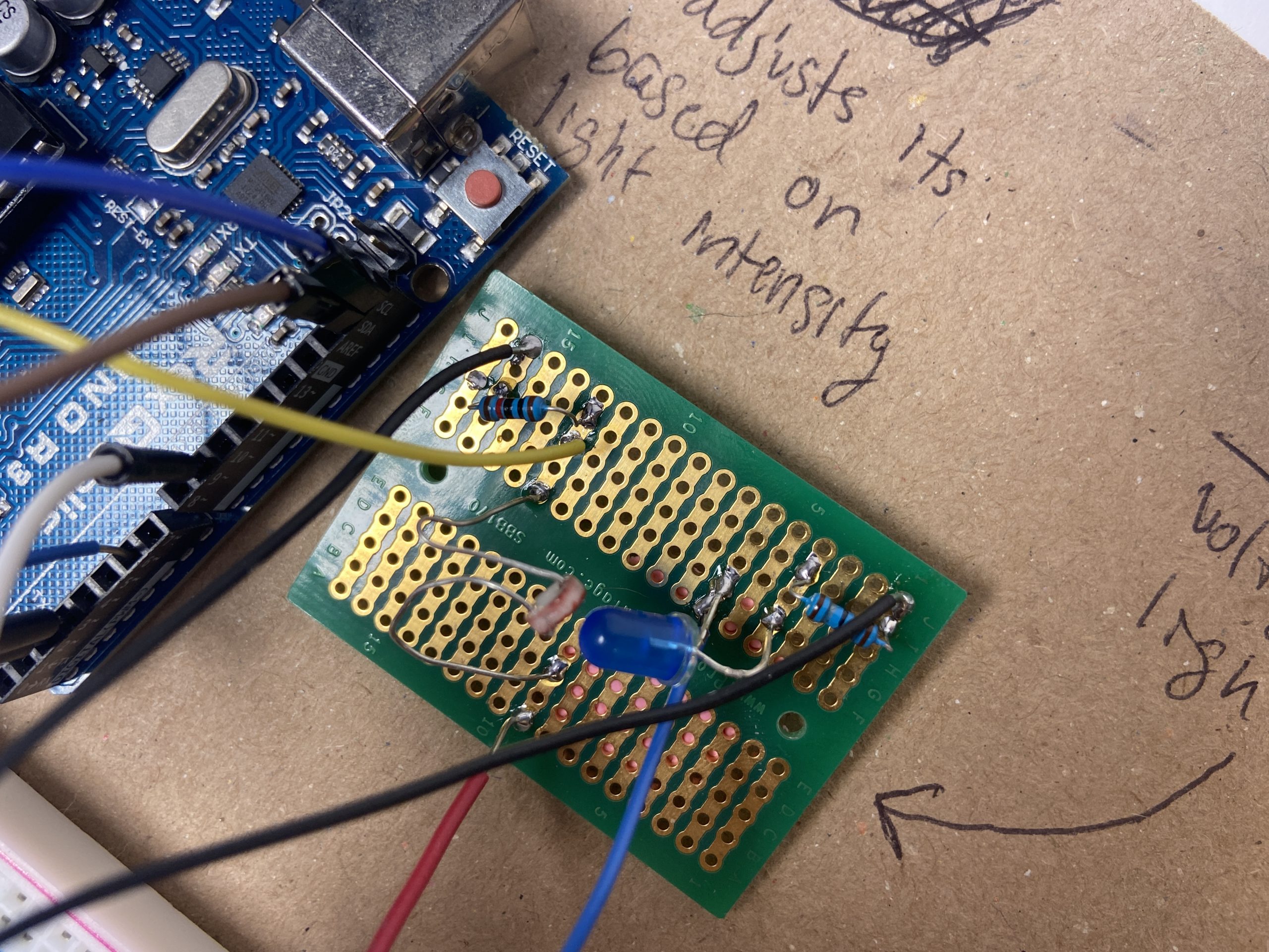
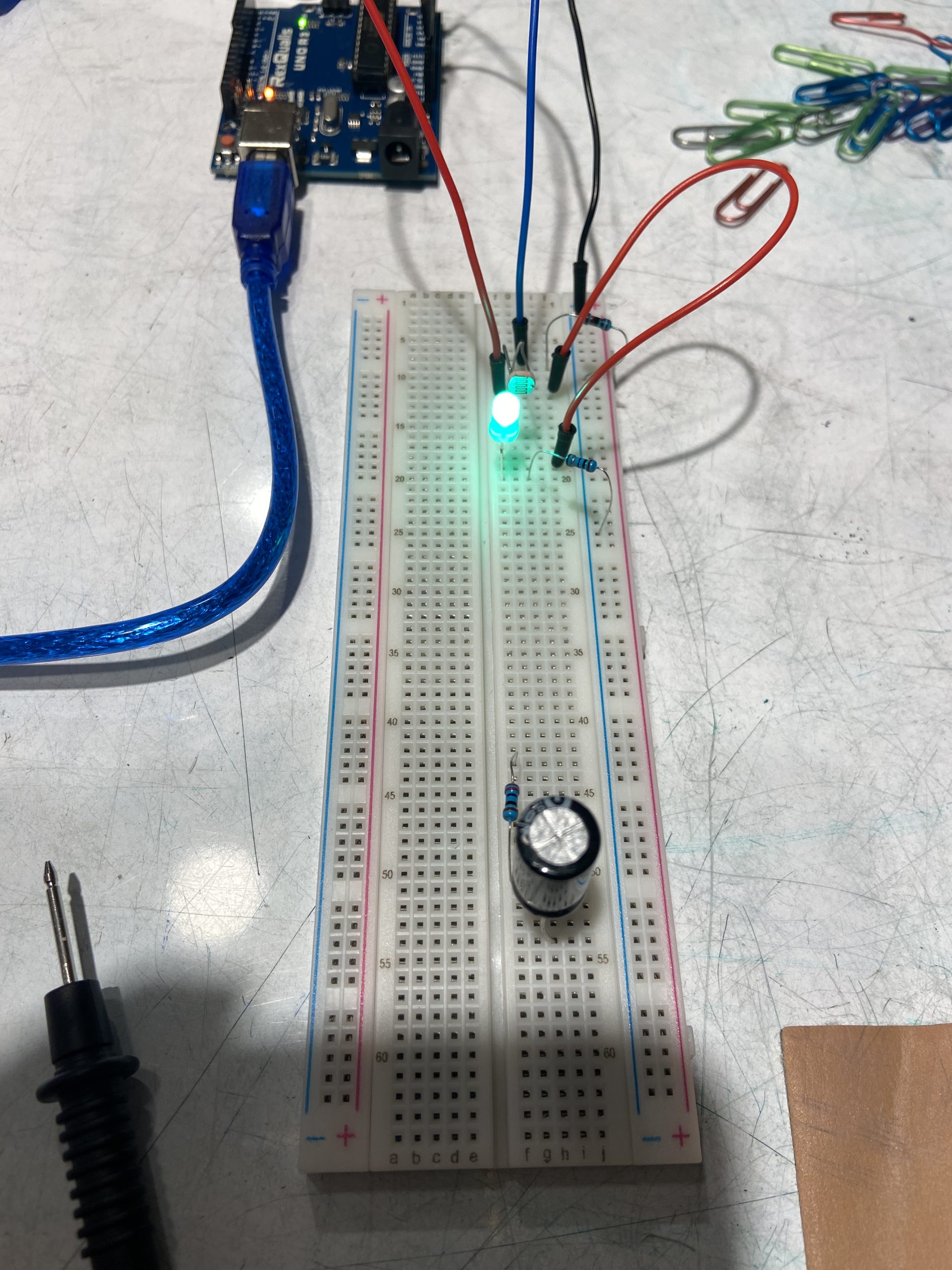
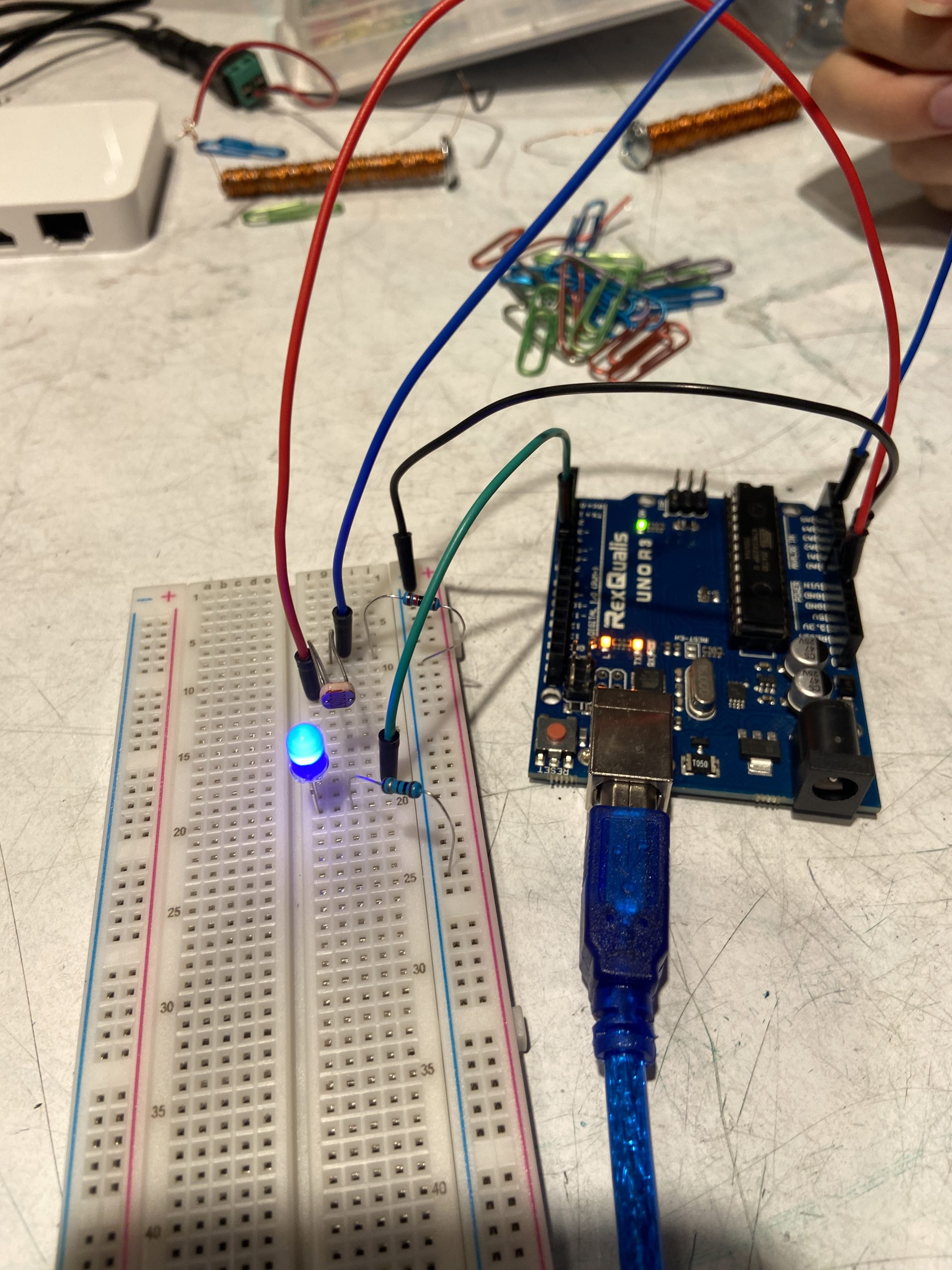
Soldered LED and photo-resistor circuit. The photo-resistor detects the brightness of the LED
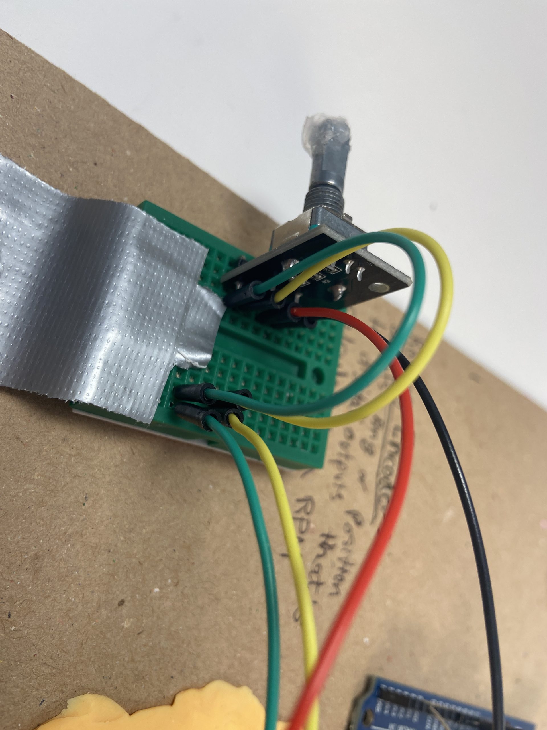
The rotary encoder wiring on a separate bread board. Reads RPM
Videos:
Simple Narrative Description
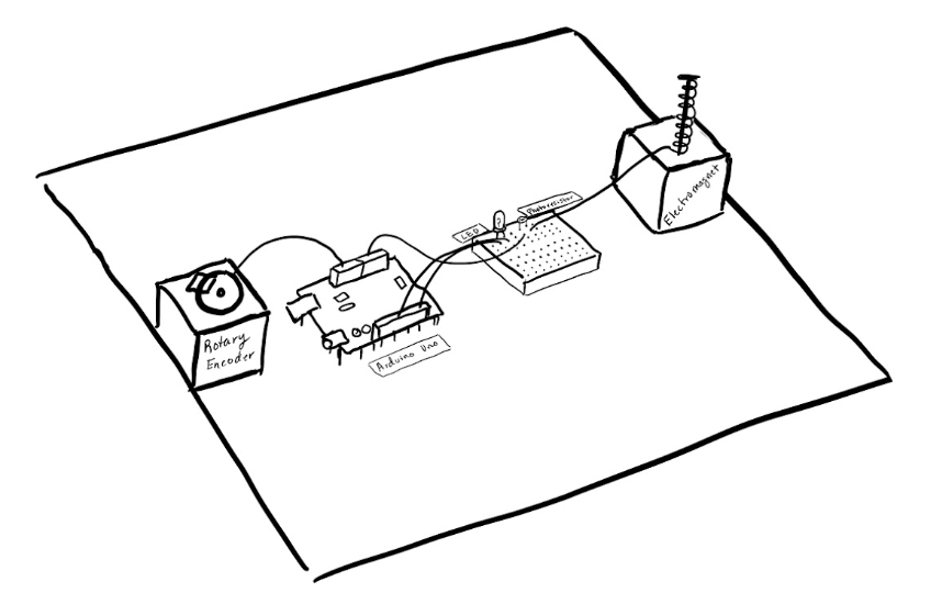
The knob measures how fast it’s spinning. This controls how bright the blue light will be, which is then measured by a light detector. The amount of light measured is used to determine how strong the magnet will be.
Process
Ideation
Or ideation for our double transducer
We had a few ideas for different energy forms, such as light, sound, and heat, as well as moving a magnet different distances. Some things, such as the sound and heat, would be hard to detect accurately, so we eliminated those ideas. Zach said the electromagnet might be a bit tricky but feasible and creative. He also recommended the simpler light transmission/detector system for the middle step, so we get more time to focus on the hard stuff.
Rotary Encoder

Getting rotary encoder to work
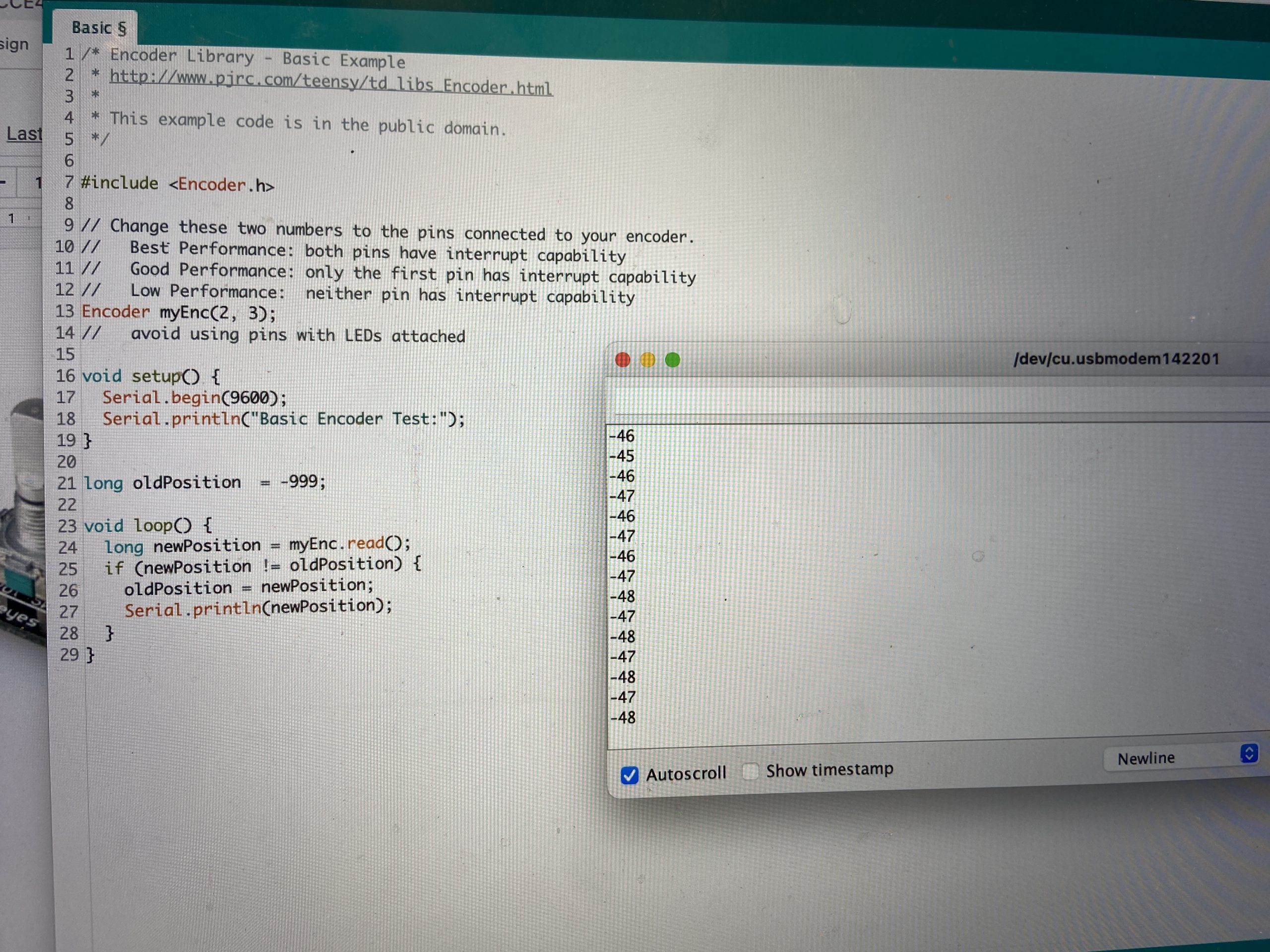
serial print screen equations
First, we learned about the Encoder library by Paul Stroffogen. We found a pin diagram online and ran the Basic code given with the library, and watched how the numbers in the Serial monitor changed as we twisted the knob. The numbers increase for rotating in one direction and decrease for the other direction, which is why you see the negative sign in the picture. We originally calculated angular velocity to convert to RPM but then switched to doing the math based on the ticks.
The fun part was obviously the math for figuring out how these numbers relate to calculating the RPM.
- Count the number of ticks it takes to complete 1 rotation: assuming the ticks are evenly spaced, then we can figure out how much of a rotation has happened by looking at the difference of two ticks.
For our rotary encoder, there were 80 ticks per rotation, which means [latex]\frac{1 rotation}{80 ticks}[/latex] so each tick is [latex]\frac{1}{80}[/latex]th of a rotation. - Time frame of measurement: counting ticks for a minute would be too slow, so it’s better to measure over a small portion of time and extrapolate the “instantaneous” RPM. We decided to measure over 1ms, since we have the millis() function in Arduino built in. Using dimensional analysis:
(x ticks/ms) * (1 rotation/80 ticks) * (60000ms/min) ends up with units of RPM.
The LED
Brighter LED
Dimmer LED
We used analogWrite to send different voltages to the LED to give it different brightness. We also used the lowest resistor and tried different colors to see what could give us the brightest LED so that the change in brightness would be most drastic. The Serial monitor shows the brightness detected by the photoresistor, which helped us find the photoresistor range also.
Electromagnet
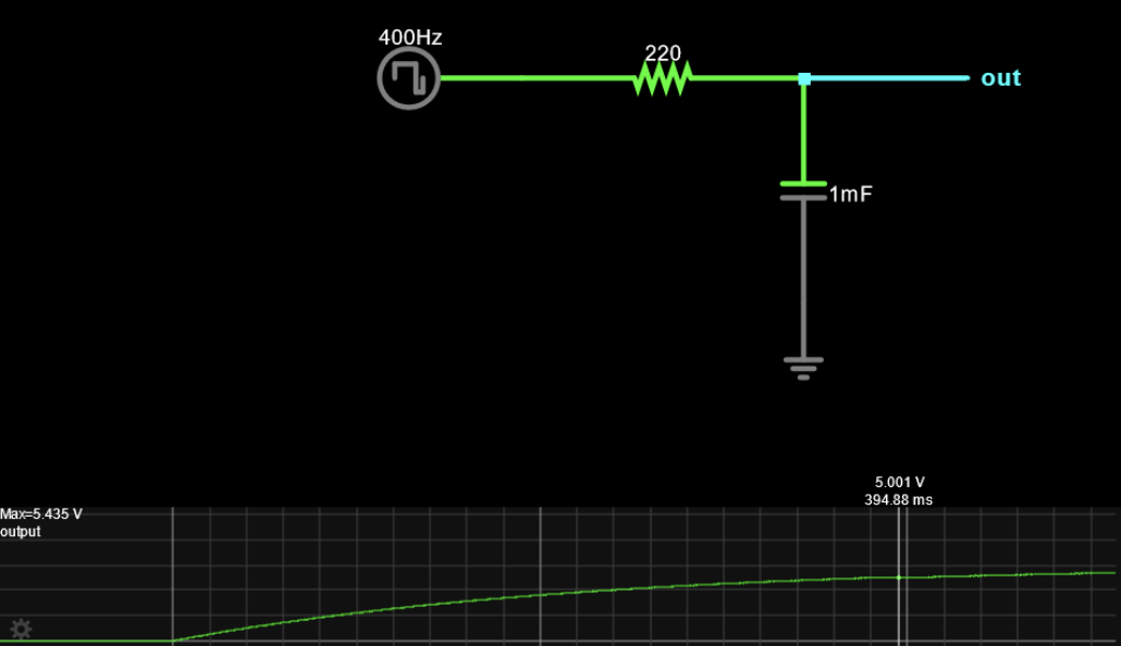
RC circuit Zach helped us simulate
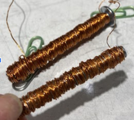
Electromagnets with different coil size and wrapping
Testing the magnetic field
https://drive.google.com/file/d/1RH2CfyKH7a7ctSiBseOcUsEurZxuO4Pa/view video of capacitor resistor circuit reacting to changing voltages
(too big to upload)
- We need to make sure the electromagnet works by itself, so we wrapped copper wire around a metal screw and drove current through it. At first, it wouldn’t pick up any paper clips at all:
- First, we added a lot more coils to make the magnet stronger.
- When that still didn’t work, we sanded the ends for a better connection with the 9V power supply we were using.
- That still wasn’t quite strong enough because it turns out the wire itself interfered with the magnetic field, so we had to sand off the outside layer. As you can see in the comparison between the 2 screws, the wire on the top (unsanded) is a stronger bronze color than the bottom screw (sanded), where you can see a lighter, more sandy/dusty brown where it was successfully sanded.
- We experimented with 2 different wire thicknesses for the coils and discovered that the thicker wire became a stronger magnet for about the same amount of coils. In addition, the thinner wire would break a lot more often when trying to sand the ends, so we like the thicker wire better.
- We learned that Arduino’s analog output isn’t truly a constant voltage, but more of a rapid cycle between the amount of time it sends 5V and 0V such that the “average voltage” is somewhere in between (Pulse Width Modulation). However, the electromagnet wouldn’t like the sudden changes between 5V and 0V, so we need to smooth out the voltage with a RC (resistor capacitor) circuit so it would become some close to “constant” voltage between 5V and 0V, turning it into a true analog voltage.
- This website simulates how the duty cycle turns into a smooth line: https://falstad.com/circuit/circuitjs.html?ctz=CQAgjCAMB0l5YCcyWrQDhAZjDA7HuugKwBMW6iYeFALNgGwjHOTMCmAtGGAFADyIWnHAM2xMKVFsZvAOZCRpIorZZSMqLwBOIUsOmrDbUht4BjI2DFHlmGbAQhu0WsmLoshPJH1IsWFCOfABKegbWbNRMkVB6VpoOtKS8APZx6nHCiJgsMPCQiHgMxAykeeC8FEIgAGIQFbhs3CAAIgCuAC4AngA6AM4Awt3mADbsvAAW2PFYvEA
- We also needed a transistor (IRLB8721PbF) in order to give the electromagnet enough current, since the Arduino doesn’t have much. The transistor takes in a voltage at the Gate terminal (output of RC circuit) and amplifies the output to the electromagnet. The value of transistors is that a small change in the Gate voltage would result in a much larger difference in the current, which would thus change the magnetic field strength.
- We started with trying the default parameters given in the website, because why not. Those values turned out to work well, so we kept those.
- We also added a heat sink to the transistor because it became hot quickly.
Discussion
While the project seemed pretty straightforward at first, there were details that we didn’t really consider that took more time than it should have. For example, even with simple parts of the system, such as the LED, we had to try different colors of LEDs/resistor combinations, because it turns out that they glow with different brightness when they all have the same amount of current. We wanted to use the brightest LED in order to give the photoresistor the widest range of values possible, since every LED can be dimmed to the same level, but not every LED can be brightened to the same level. Other small things that took longer than it should have included needing to sand all the wire used around the electromagnet, since we didn’t realize that the coating could interfere with the magnetic field until we tested it. Another problem we ran into was that the LCD would flash in order to refresh the correct values, and we tried for a while to get rid of the flashing at first, but couldn’t. So we realized it was probably just a necessary quirk of the system. Also we realized that we should’ve put more time into figuring out the LCD because ours didn’t end up working properly and it was most likely a little mapping issue we missed.
Secondly, for some reason one of the circuits that was working normally before suddenly decides to shut off whenever the rotary encoder spins. Not sure why that happens, and Zach wasn’t able to figure it out either. Another team suggested later that it could be that the other components use too much power, causing the Arduino to shut off. Of course, there could be other issues such as poor connections as well, but we double checked those, and again, it was working before without modifying anything.
If we were doing this again, perhaps we could consider doing different strategies for dividing the work. For this project, we both worked on the same part of the system at once. The benefits were that we both learned more deeply about each part of the circuit, and could help each other debug better because of it. However, this may not have been the most time efficient approach, since the output produced would be limited to whatever part of the system we were doing, instead of perhaps being able to make progress on multiple parts at once. But at the same time, by each working on different parts, perhaps we wouldn’t have as deep of an understanding of each step, and thus be less effective at helping each other debug. Perhaps we could take a mixture of these approaches and do the easy parts concurrently, but work on the hard parts together.
Functional block diagram and schematic

Code
/* Double Transducer: RPM to Magnetism
Gia Marino and Freda Su

Our code takes inputs from a rotary encoder and translates them to positions on a
tiny circle in the encoder. We used these positions to calculate the RPM based on
the number of ticks that go by. Then we take that number and map RPM into a
0 to 255 so that the LED can change brightness based on the rotation speed. Then we
have the photoresistor that reads the brightness of the LED and maps it into a range
of 0 to 255 so it can send a voltage to our electromagnet. Lastly, the code takes the
RPM, LED input value, LED brightness, and input value into the electromagnet and maps
it into a range of 0-99. then prints it on the LCD screen

 Arduino pin | role   | description
 ------------|--------|-------------
 A3            input    photoresistor pin
 9             output   electromagnet pin
 6             output   LED pin
 2             input    rotary encoder pin A
 3             input    rotary encoder pin B
 SDA           output   LCD serial pin
 SCL           input    LCD clock pin
 GND           input    ground
 5V            output   5v

We based our if statement for the rotary encoder around Paul Stoffregen's Encoder
library code: https://github.com/PaulStoffregen/Encoderthe, specifically the "basic"
example that comes with the library. We had a lot of assistance and influence from Remy's
code for the LCD display (https://github.com/remyfrank01/Double-Transducer/blob/main/DOUBLE_TRANS.ino).
Lastly, we copied the LCD tutorial code and worked off of that, so our code for the LCD display
is also heavily influenced by this tutorial: https://courses.ideate.cmu.edu/60-223/f2022/tutorials/I2C-lcd*/


#include <LiquidCrystal_I2C.h>  ////https://courses.ideate.cmu.edu/60-223/f2022/tutorials/I2C-lcd
#include <Wire.h> //LCD display
#include <Encoder.h> //https://www.pjrc.com/teensy/td_libs_Encoder.html

const int PHOTOPIN = A3; // photoresistor pin
const int LEDPIN = 6; // LED pin
const int EMPIN = 9; // electromagnet pin
const int totalTicks = 48; // amount of steps in one full rotation of the rotary encoder
const double anglePerTick = 1.0/totalTicks; // one Rotation/total ticks

/* Create an LCD display object called "lcd" with I2C address 0x27
    which is 16 columns wide and 3 rows tall. You can use any name you'd like. (col, row)
    (0,0) (1,0) (2,0) ... (15,0)
    (0,1) (1,1) (2,1) ... (15,1)*/
LiquidCrystal_I2C lcd(0x27, 16, 2);
Encoder myEnc(2,3); //pins 2 & 3 should have interrupt capablility

void setup() {
  pinMode(PHOTOPIN, INPUT);
  pinMode(LEDPIN, OUTPUT);
  pinMode(EMPIN, OUTPUT);
  Serial.begin(9600);
  Wire.begin();

  // initialize the lcd (only need to do this once)
  lcd.init();

  // turn on the backlight to start
  lcd.backlight();
  lcd.clear();

}

unsigned long time0 = millis(); // time since last checked the rotary encoder
unsigned long timerLCD = millis(); // timer used for LCD dispkay
long oldPosition = -999;
float angVel; // anglular velocity
unsigned int brightness = 0; //the input for the LED that controls the brightness
unsigned int photoVal = 0; // the value we get from the photoresistor
unsigned int voltage = 0; // electromagnet voltage
unsigned int rpm = 0; // rotations per min calculated from rotary encoder steps


void loop() {

unsigned long globalTime = millis();

  long newPosition = myEnc.read();

  // convert ticks to rpm
  if (globalTime - time0 >= 1) { // checks every second
    double countTicks = abs(newPosition - oldPosition); // figures out how many steps passed by
    oldPosition = newPosition;

    // reset time so when loop runs again we base our math on the most recent last position
    time0 = globalTime;

    angVel = countTicks * anglePerTick;
    rpm = angVel * 60000; // converts just calculated angular velocity to RPM
  }

    // takes RPM and calculates a mapped output voltage so brightness is affected by rpm speed
    brightness = map(rpm, 0, 60, 0, 255);  //120-360 deg/sec to 0-255 analogWrite
    analogWrite(LEDPIN, brightness);

    //takes photoresistor value and maps an output voltage for the electromagnet so
    // it varies based on the photoresistor values
    photoVal = analogRead(PHOTOPIN);
    voltage = map(photoVal, 0,1023, 0, 255); //adjust photoVal range: 0-1023 photoVal to 0-255 analogWrite
    analogWrite(EMPIN, voltage);

  //LCD display

  if (millis() - timerLCD >= 250) {// every 1/4 sec
    timerLCD = millis();  //reset
    lcd.clear();
    // set cursor to home position, i.e. the upper left corner
    lcd.home();
    int mappedRPM = map(rpm, 0, 60, 0, 99);
    if (mappedRPM > 99) mappedRPM = 99;
    else if (mappedRPM < 0) mappedRPM = 0;
    lcd.print("i:" + String(mappedRPM));  //convert to rpm

    lcd.setCursor(6,0);  //middle of first row
    int mappedBrightness = map(brightness, 0, 255, 0, 99);
    if (mappedBrightness > 99) mappedBrightness = 99;
    else if (mappedBrightness < 0) mappedBrightness = 0;
    lcd.print("m:" + String(mappedBrightness)); //convert brightness
    // move cursor to column 8, row 1

    lcd.setCursor(8, 1);
    int mappedPhotoVal = map(photoVal, 0, 1023, 0, 99);
    if (mappedPhotoVal > 99) mappedPhotoVal = 99;
    else if (mappedPhotoVal < 0) mappedPhotoVal = 0;

    lcd.print(String(mappedPhotoVal));
    // move cursor to column 13, row 2
    lcd.setCursor(12, 1);

    int mappedVoltage = map(voltage, 0, 255, 0, 99);
    if (mappedVoltage > 99) mappedVoltage = 99;
    else if (mappedVoltage < 0) mappedVoltage = 0;
    lcd.print("o:" + String(voltage));
  }

  //goes to RC circuit, transistor etc

}