In this project, we as a team worked together to create a device to improve the life of a physically disabled person living in Pittsburgh. Crucially, the device is tailor made to our client, useful and relevant for them in particular, driven by their wants and needs, and nobody else’s. Designing over the course of seven weeks with our client Dennis, we conducted a needfinding interview, distilling into a concept for his device. (The notes from that interview can be found here: https://courses.ideate.cmu.edu/60-223/f2022/work/team-vela/)
What We Built
We created a light-up emotional display, allowing Dennis to show 5 different emotions ranging from happy to sad. These emotions correspond to five distinct light colors, from green (happy) to red (sad). These emotions and lights are controlled via a dial on an accessible control panel. Additionally, if Dennis has a question, he can press a button on his control panel, turning the lights purple. Finally, if Dennis has an emergency and needs to get someone’s attention, he can flip a two-part switch to turn the lights red and play a noise.
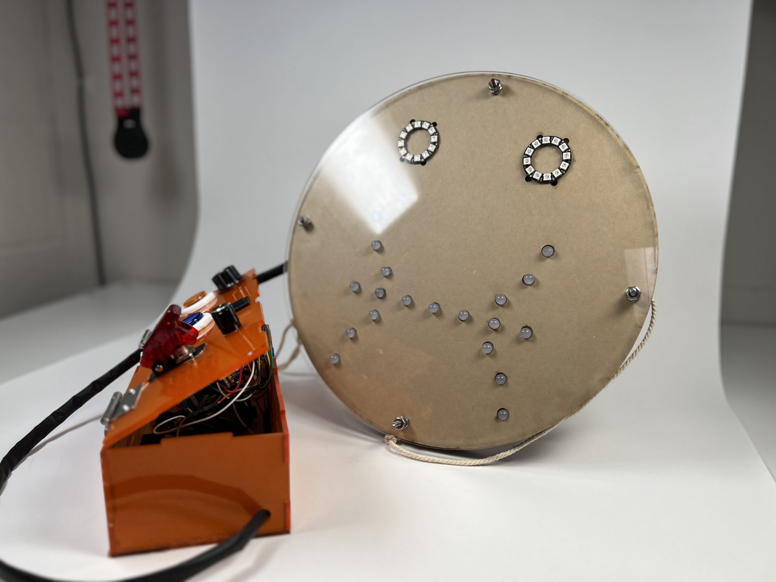
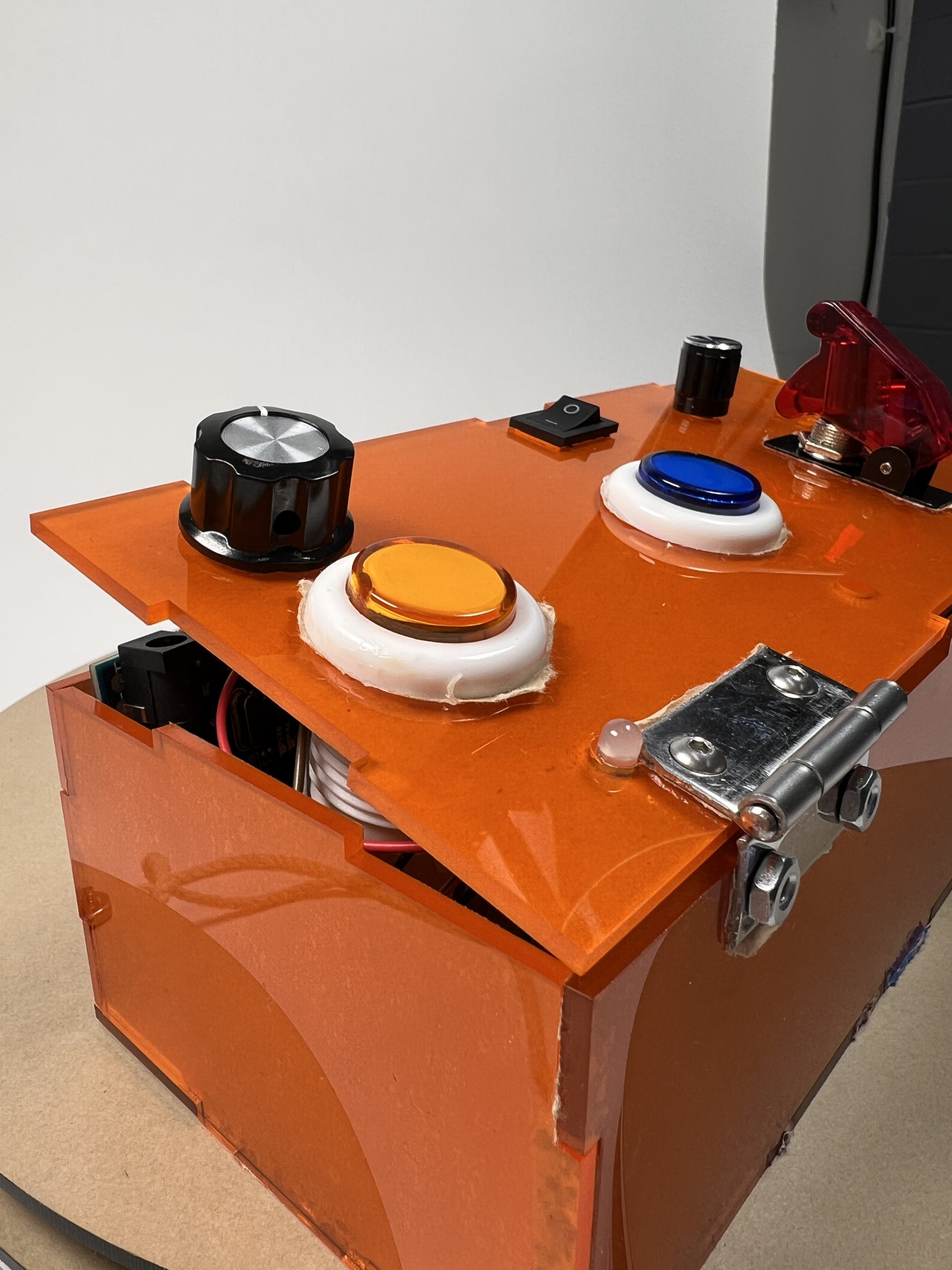
Final prototype with face display and control box.
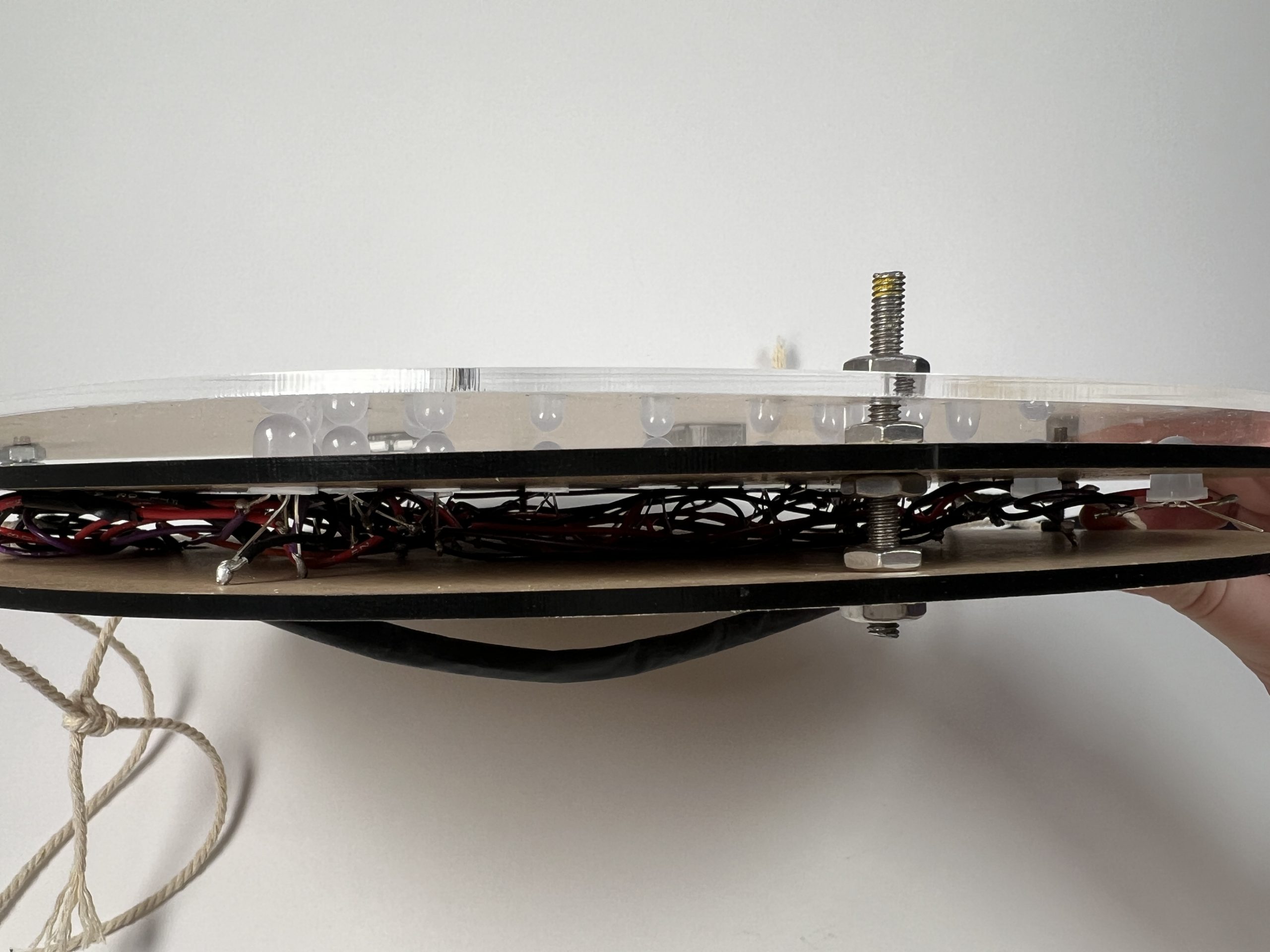
Side profile of face plate, showing the three acrylic layers, screw attachments, LEDs, and wiring.
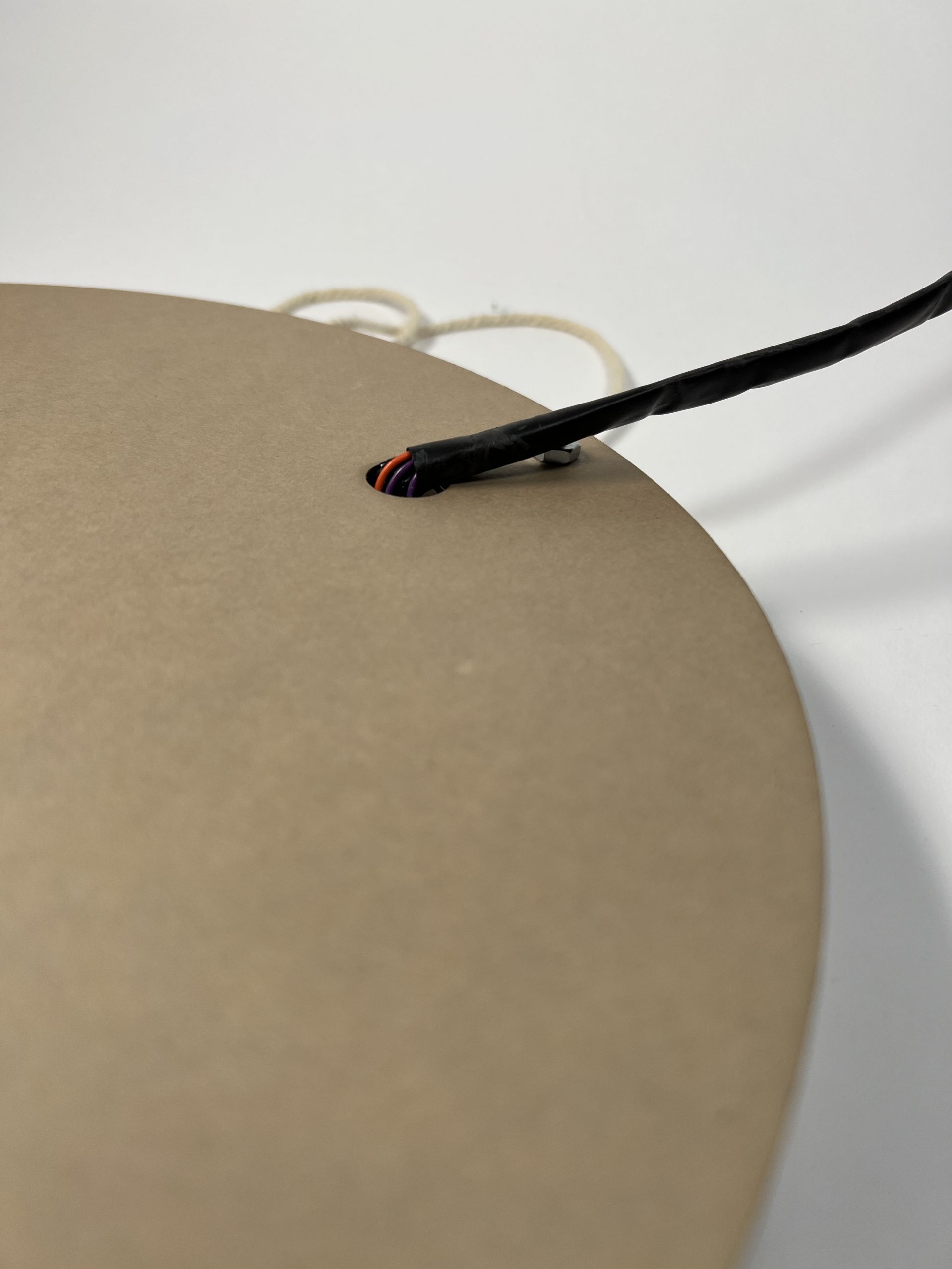
Heat shrink-wrapped wires and exit hole from the back of the face plate.
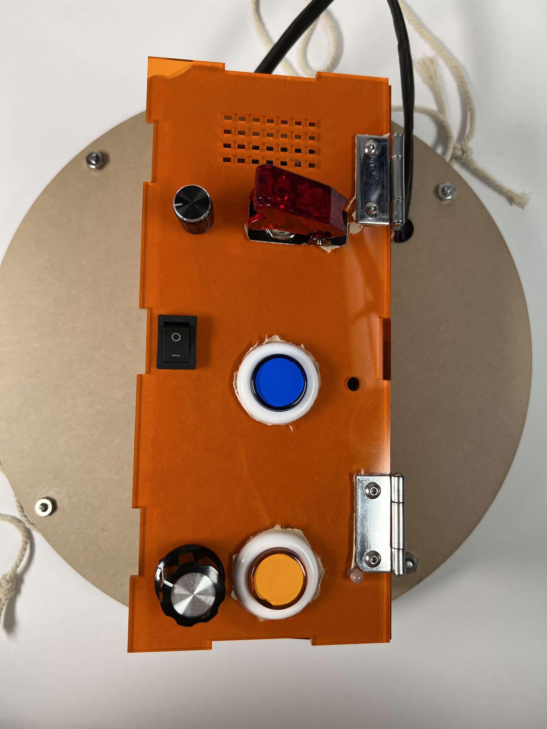
Control box. From top to bottom: red emergency switch and dial for noise volume, blue button (toggling the question mode) and on/off switch, yellow button (toggling emotions mode) and dial for emotional status.
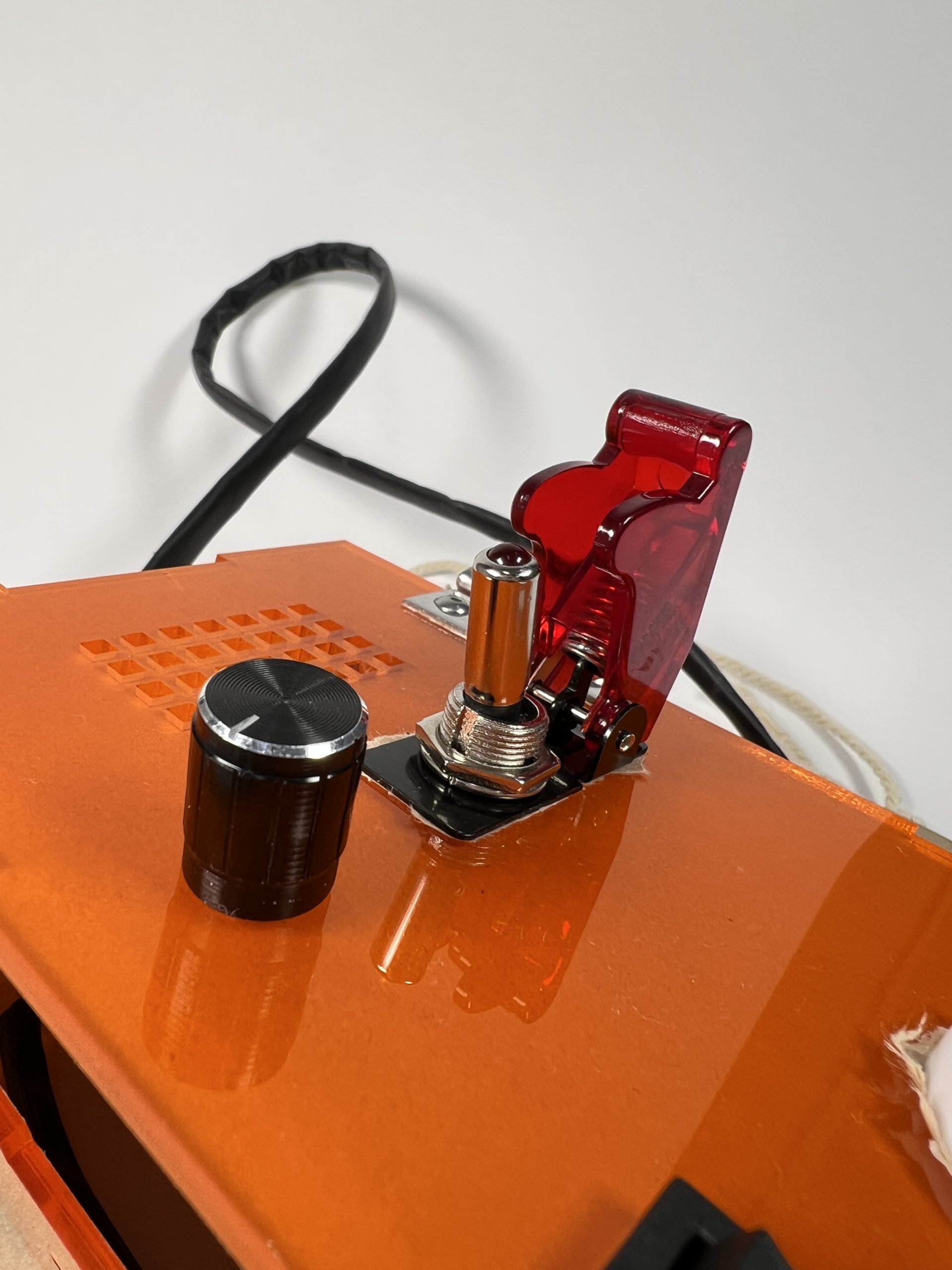
Emergency switch with the cover pushed back, primed to be flipped.
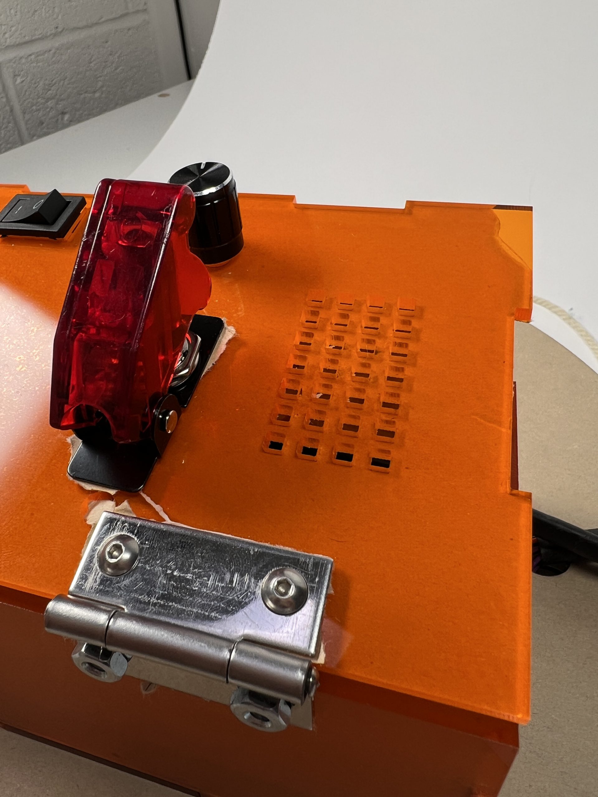
Textural “breadboard” feature, as requested by Dennis.
Close-up of emotions mode toggle button and emotional status dial.
Narrative Sketch
Dennis is out to lunch in Shadyside with some of his friends and staff from CLASS. His company is good, the food tastes great, the weather is nice, and he is having an excellent time. So, Dennis flips the on switch to his emotions display and turns the dial to show to others that he is happy being out to lunch with everyone. In addition to informing the people with him, the bright green lights and smiling face clearly display positive emotion, encouraging the strangers at the restaurant to approach Dennis to say hi—an opportunity to make new friends! After a great conversation, Dennis goes back to his lunch.
Later, Dennis decides that his sandwich is a little bland and he would like to put some salt on it. Unfortunately, he is unable to reach across the long table to the salt shaker. Dennis presses the button on his control panel to indicate that he has a question. The display lights up purple and displays a neutral face. A light on his control panel displays this purple as well, informing the people at the table that Dennis would like some help. They fortunately notice it quite quickly. Dennis is able to ask for the salt for his sandwich, which is passed to him.
By using the emotional face display, Dennis has been able to make himself both more approachable and better understood. Furthermore, it is able to ease some of this social frustrations by letting the people around him know he has an issue quickly and efficiently.
How We Got Here (Prototype and Process)
This prototype was designed to help answer the design question: How can we help Dennis communicate with the world better?
Prototype
Our prototype was a light-up emotional display, capable of showing five different “emotions” through shades of color across three faces. Additionally, the display has two additional modes to the emotions mode: question, with an additional color, and emergency, which plays noise.
Our single prototype was slowly constructed across prototyping its parts, eventually coming together into the final construction.
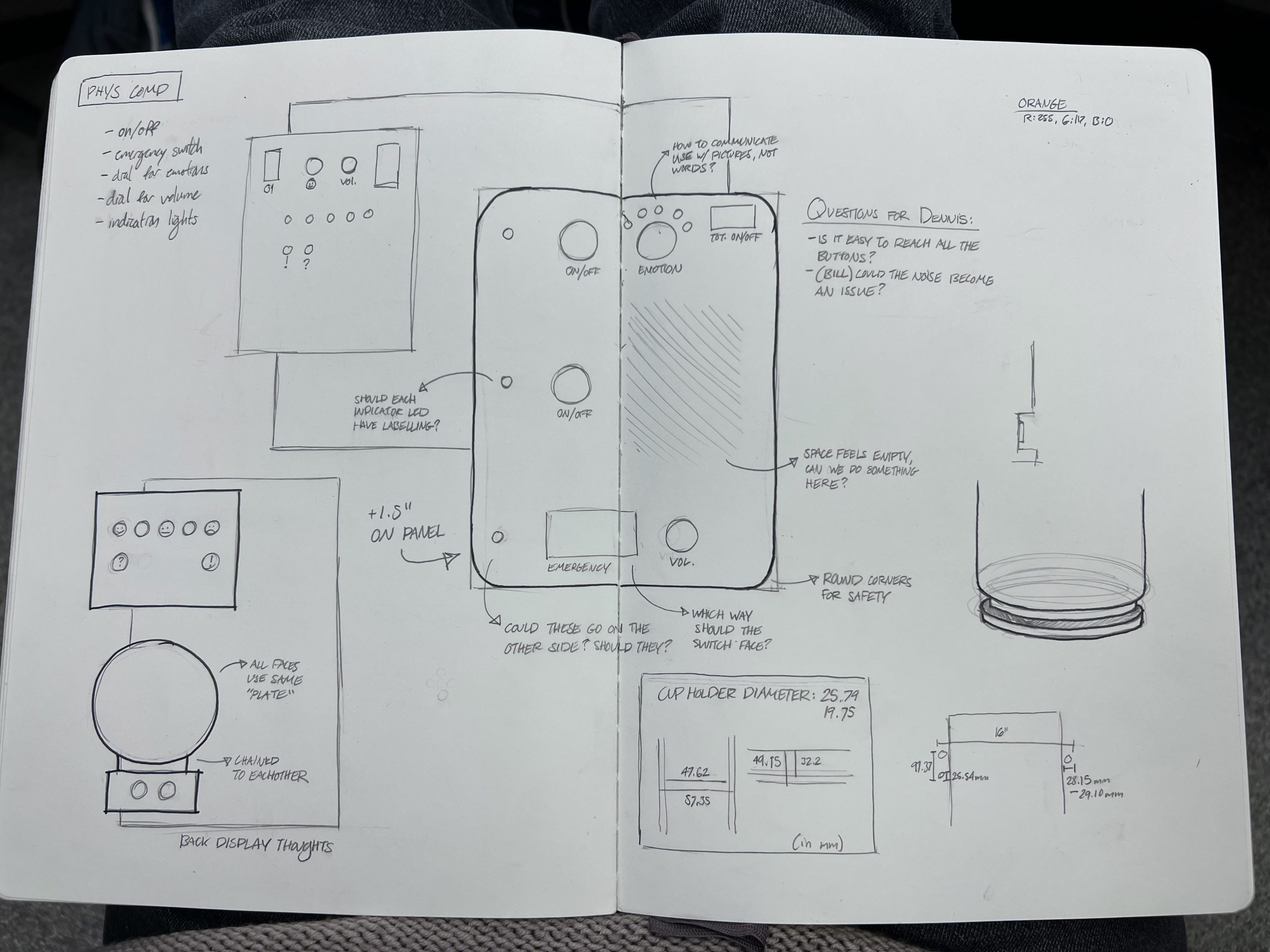
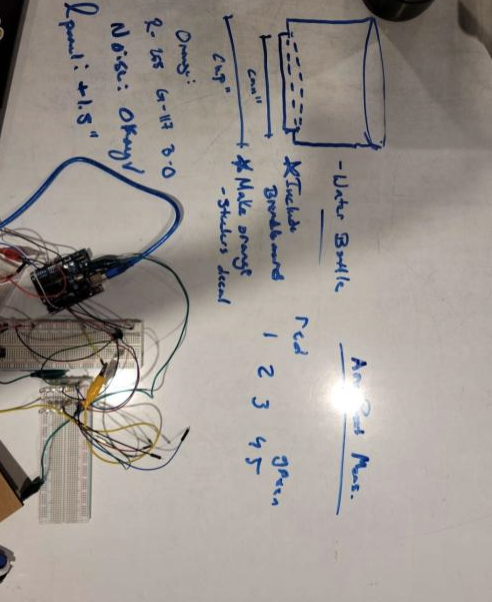
Sketch of control panel and other accessories.
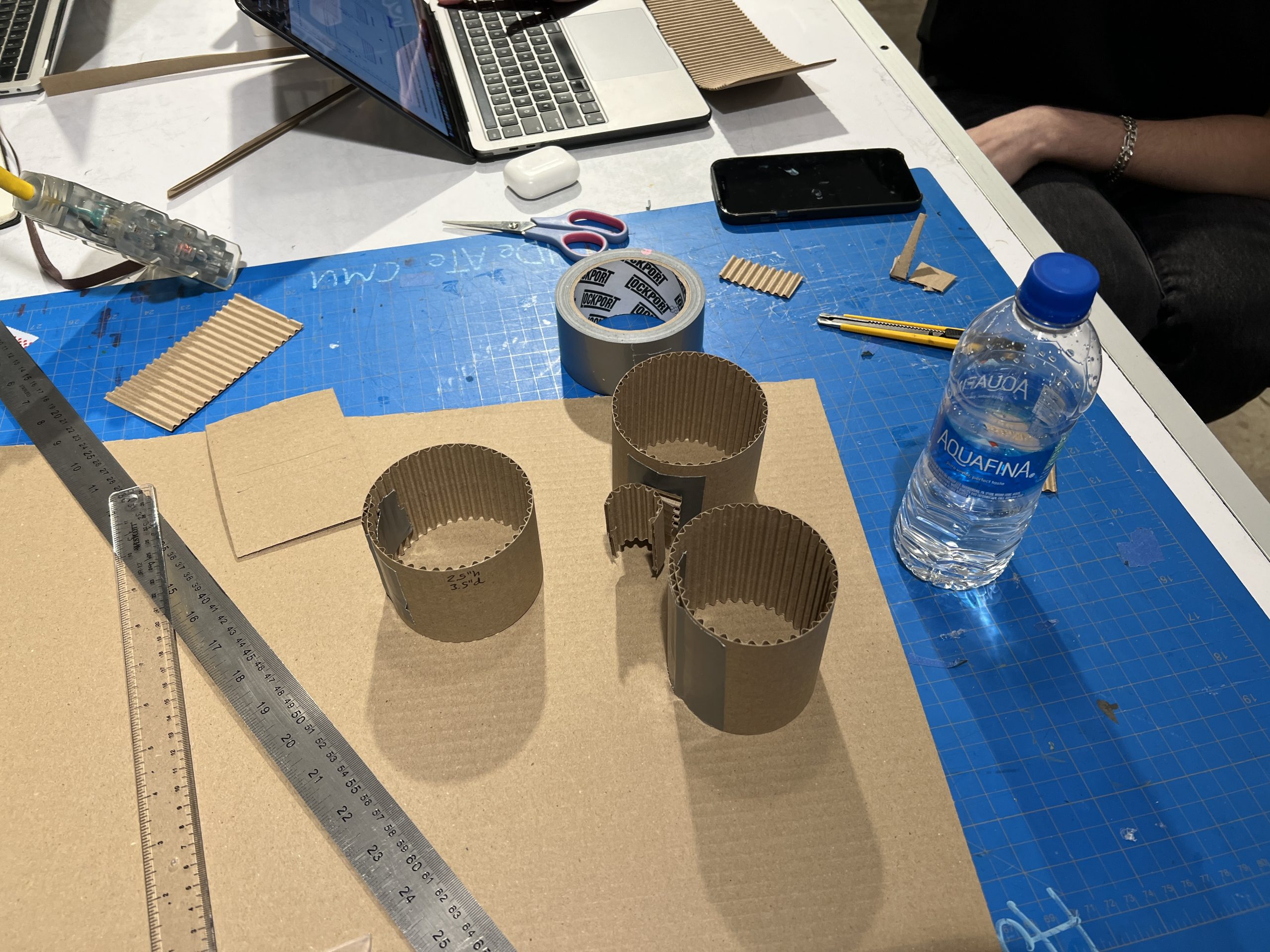
Three of our cardboard cupholder prototypes.
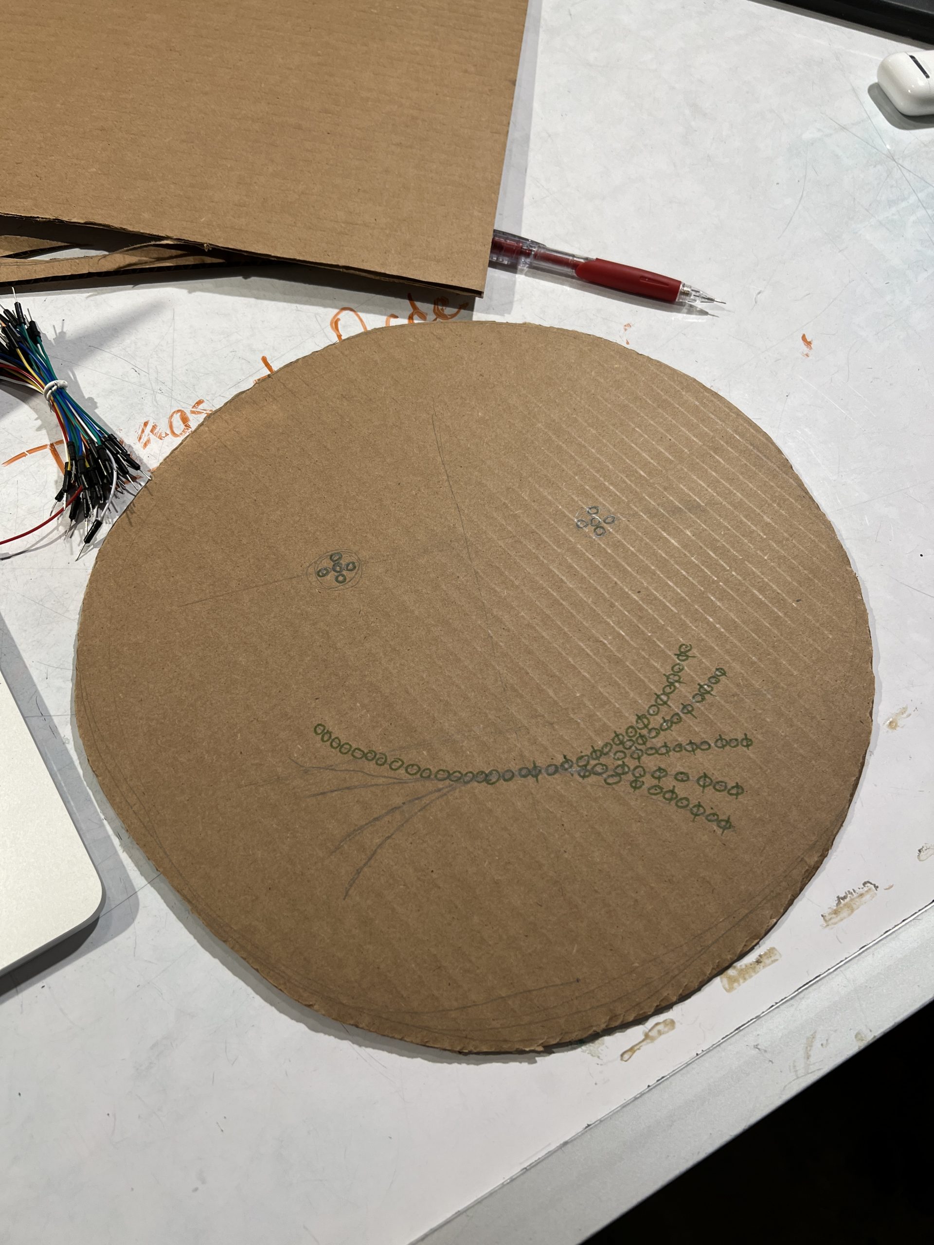
First sketch of face plate model with potential placement of LEDs. These were later significantly reduced.
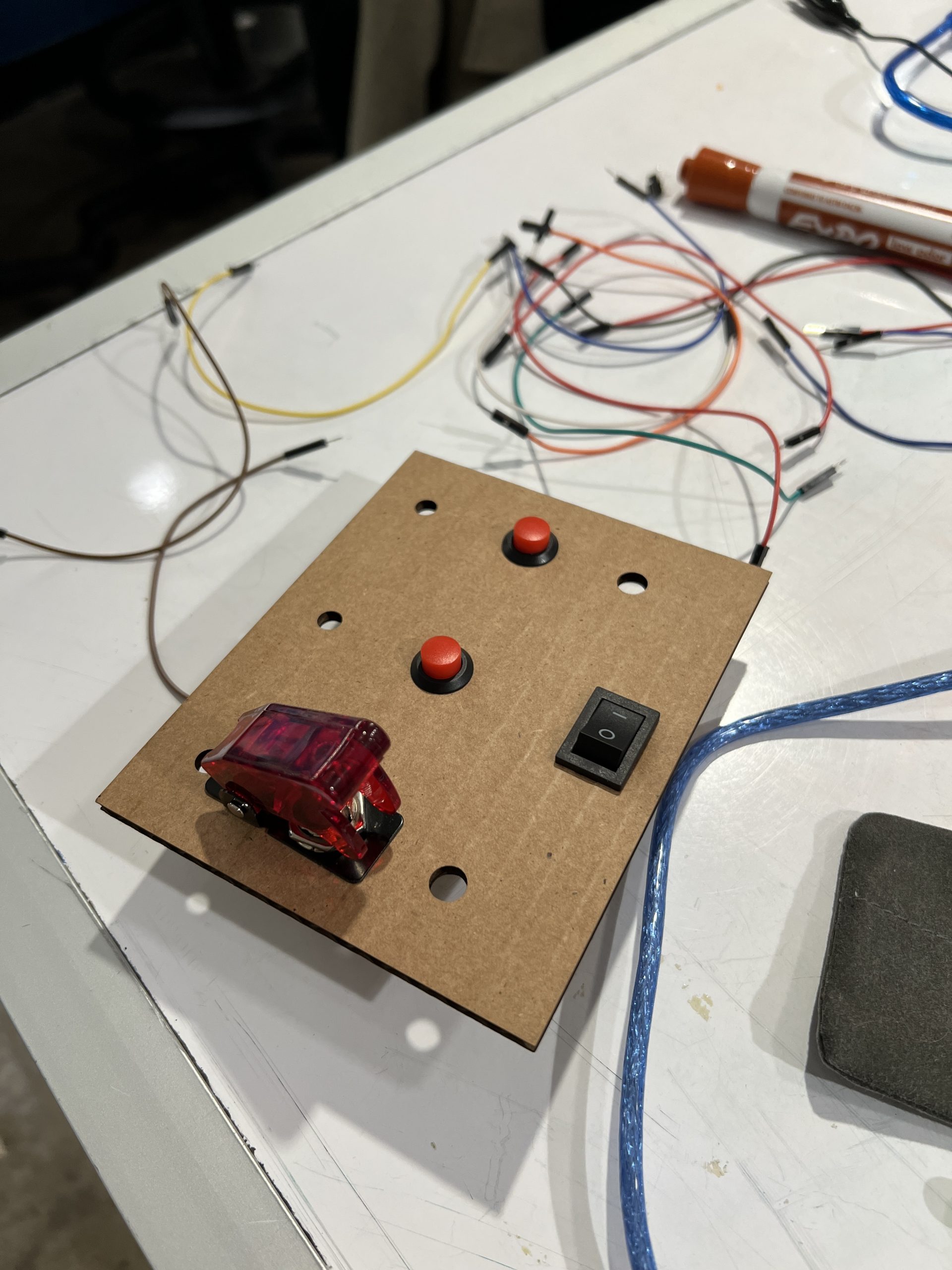
First laser cut of the control panel, with potential buttons and switches inserted.
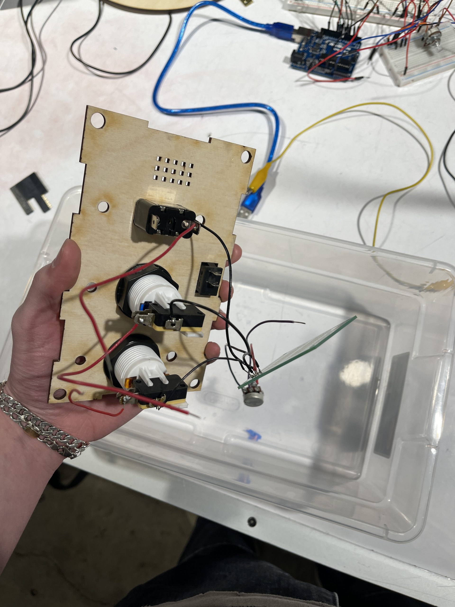
Second laser cut of control panel, this time out of wood, with new buttons and switches inserted.
Measurements taken to plan integration and development of the cup holder.
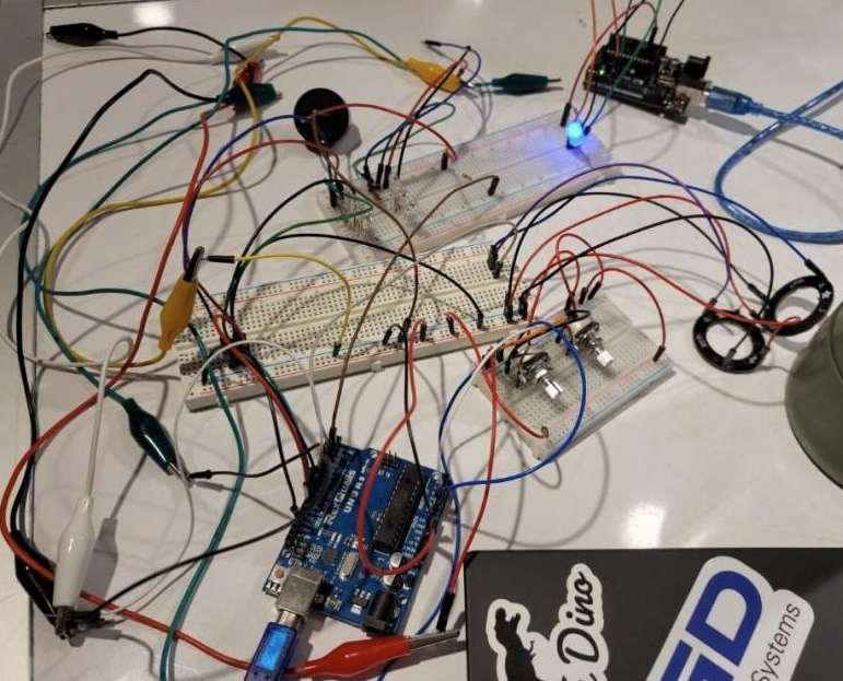
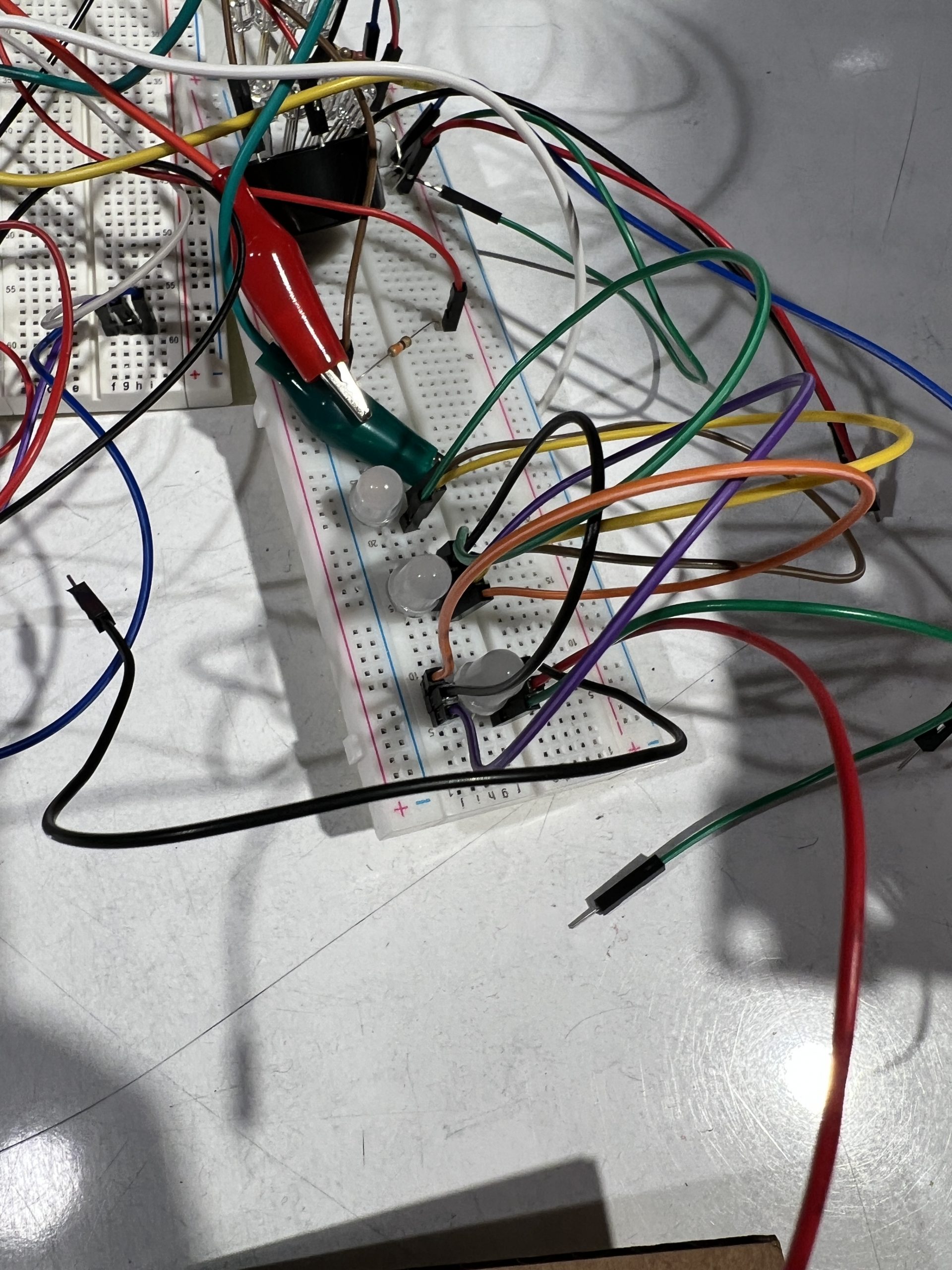
Development process and testing of the wiring/circuitry.
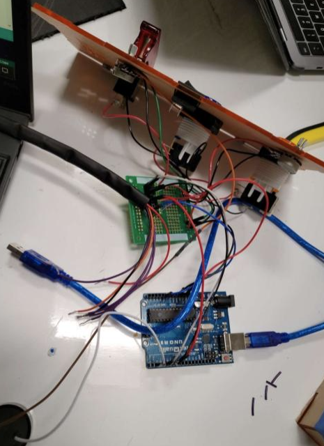
Testing of soldered circuitry and integration with PCB board.
As we worked through our prototyping process, we wanted to be cognizant of creating a device that Dennis could use easily, taking into account his limited hand stability and mobility due to arthritis. This was particularly true with the control panel for the display. Although the less flashy part of the design, the control panel was also ultimately what Dennis would be experiencing the device through. If our panel couldn’t be used, neither could the device as a whole.
In a subsequent meeting with Dennis to review our prototype, we came out with much helpful feedback. Dennis was happy with how the device was coming along overall and happy with the progress we had made thus far—but it was not perfect. By discussing with Dennis, we found that it’s easier for him to have larger buttons with slightly larger space in between those buttons. Tied to this, we found that it would be better with a slightly larger total control panel. Originally, we were trying to create the smallest possible panel in hopes that a smaller panel would impede Dennis’ and Dennis’ wheelchair as little as possible, but decided that Dennis’ comfort in using the panel was a very reasonable compromise for a slightly larger design. Importantly, Dennis was also able to quickly pick up on the interface we had designed. In terms of adjacent feedback, we asked Dennis about how he would like his device to appear visually. He was happy with our physical models, but did specifically request that his device was orange and potentially included some Steelers decals. This was inspired by another wheelchair user he had met who had pink accessories to match her pink wheelchair. Finally, we asked Bill, who helps to care for Dennis at CLASS if noise implementation for the “emergency” mode would become disturbing. He didn’t think so, so the noise translated into our final design.
Overall, we incorporated all of the feedback we received from Dennis and Bill into our final prototype. The critique—both negative and positive—truly helped to inform our total design process and steer us in the right direction for our final implementation. Seeing the delight created by the device as a whole was a great driver for the next parts of the process.
Process
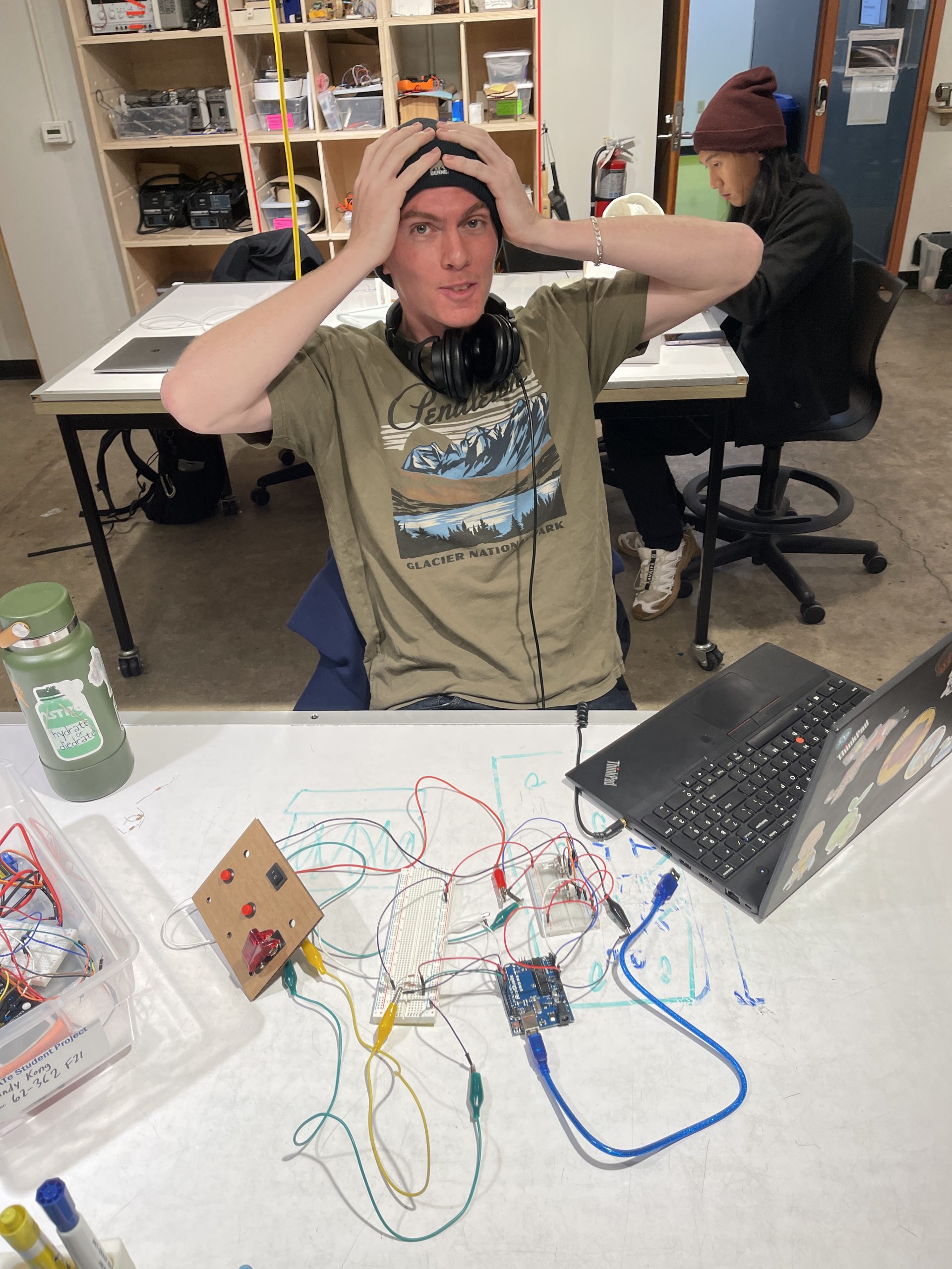
A very stress-free process photo, including first iteration cardboard control board and Remy testing code.
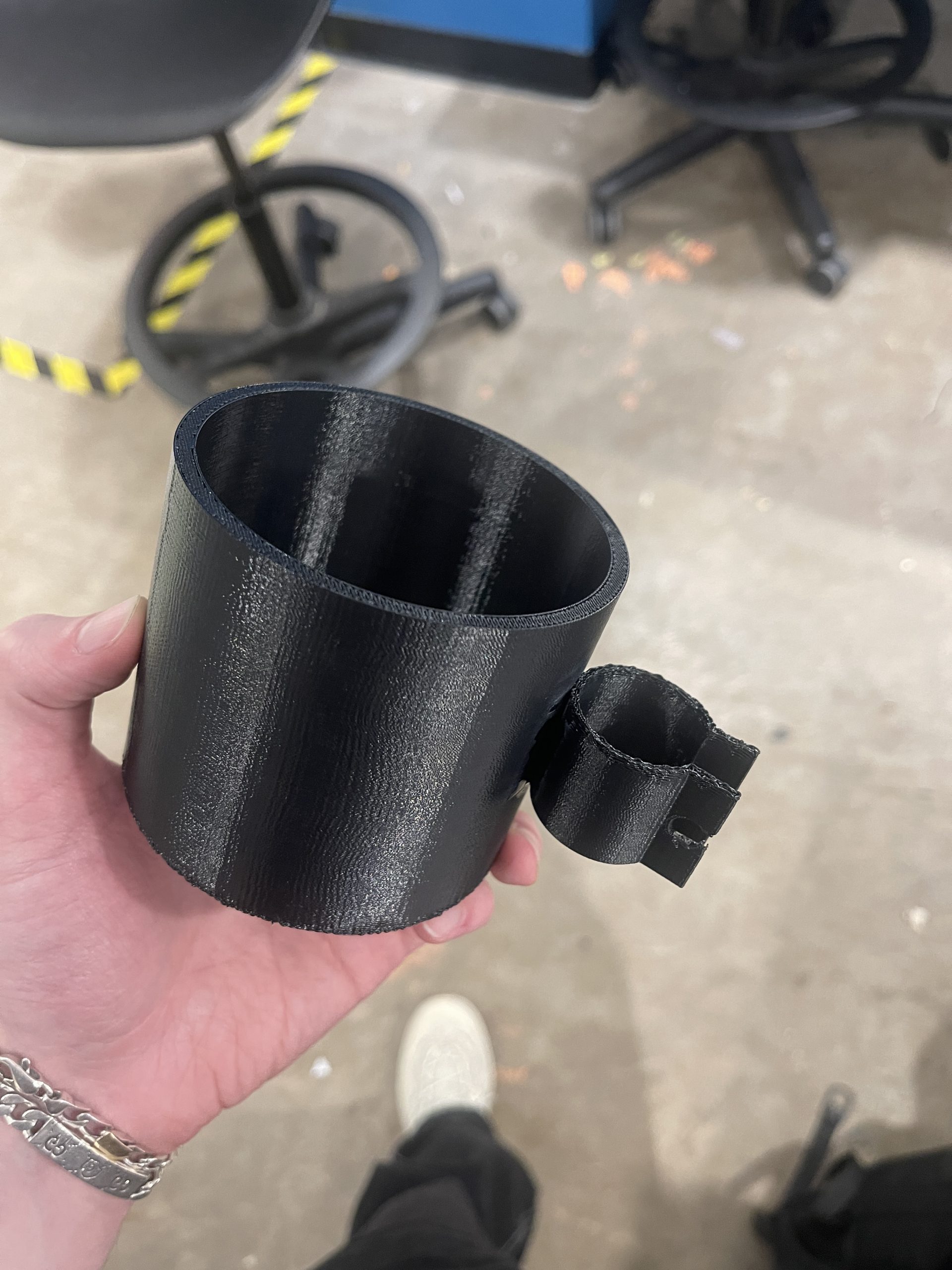
Final 3D print of Dennis’ cup holder.
Our process, as many processes often are, was wrought with things not quite working out the way we were planning. We started by following the Gantt chart closely, but that quickly fell to the wayside—to our detriment. We were on track for the CAD designs and electronics programming, but fell behind beginning with the circuit build.
Testing the LEDs in series before soldering them together.
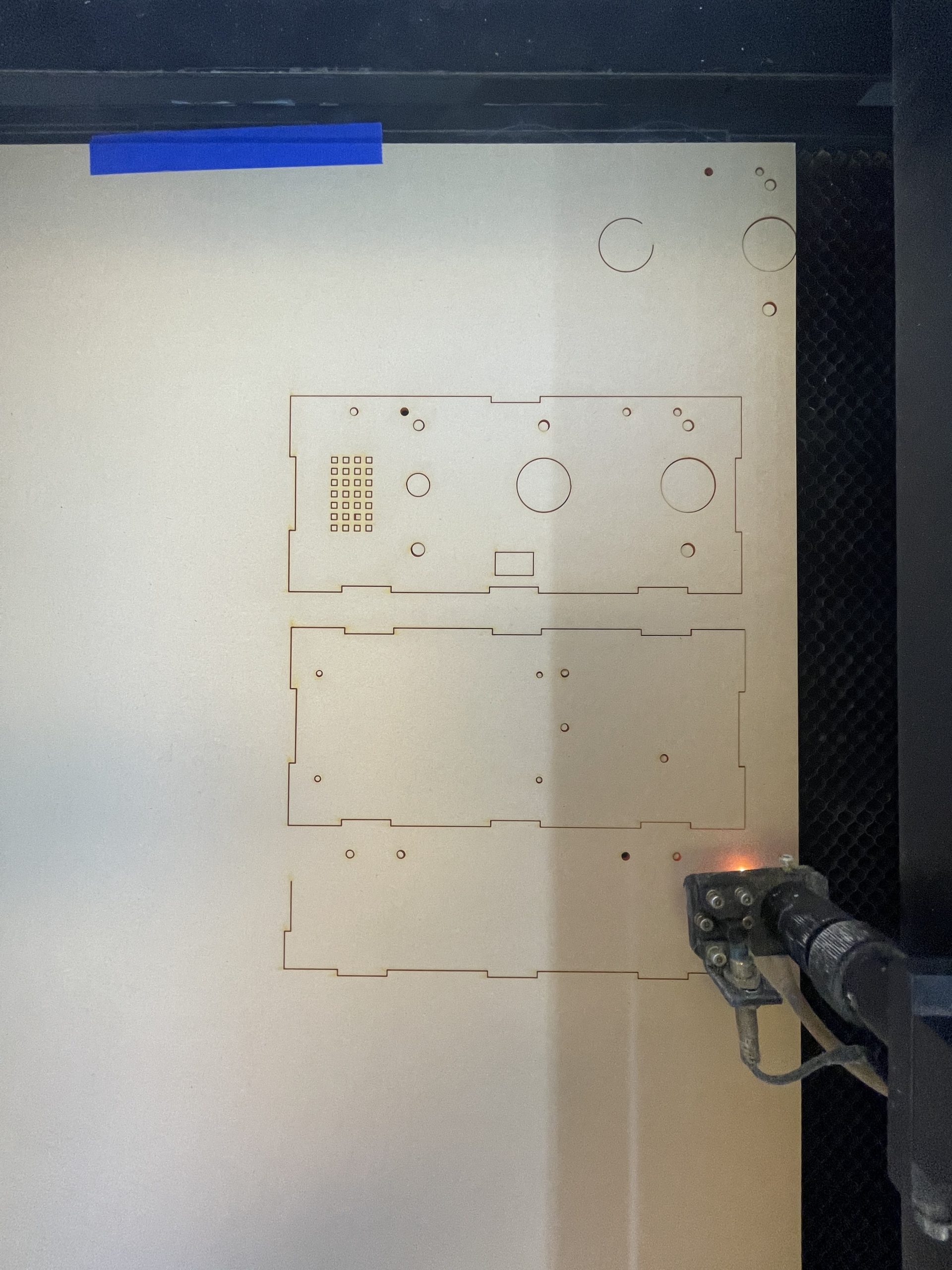
Laser cutting the final control box.
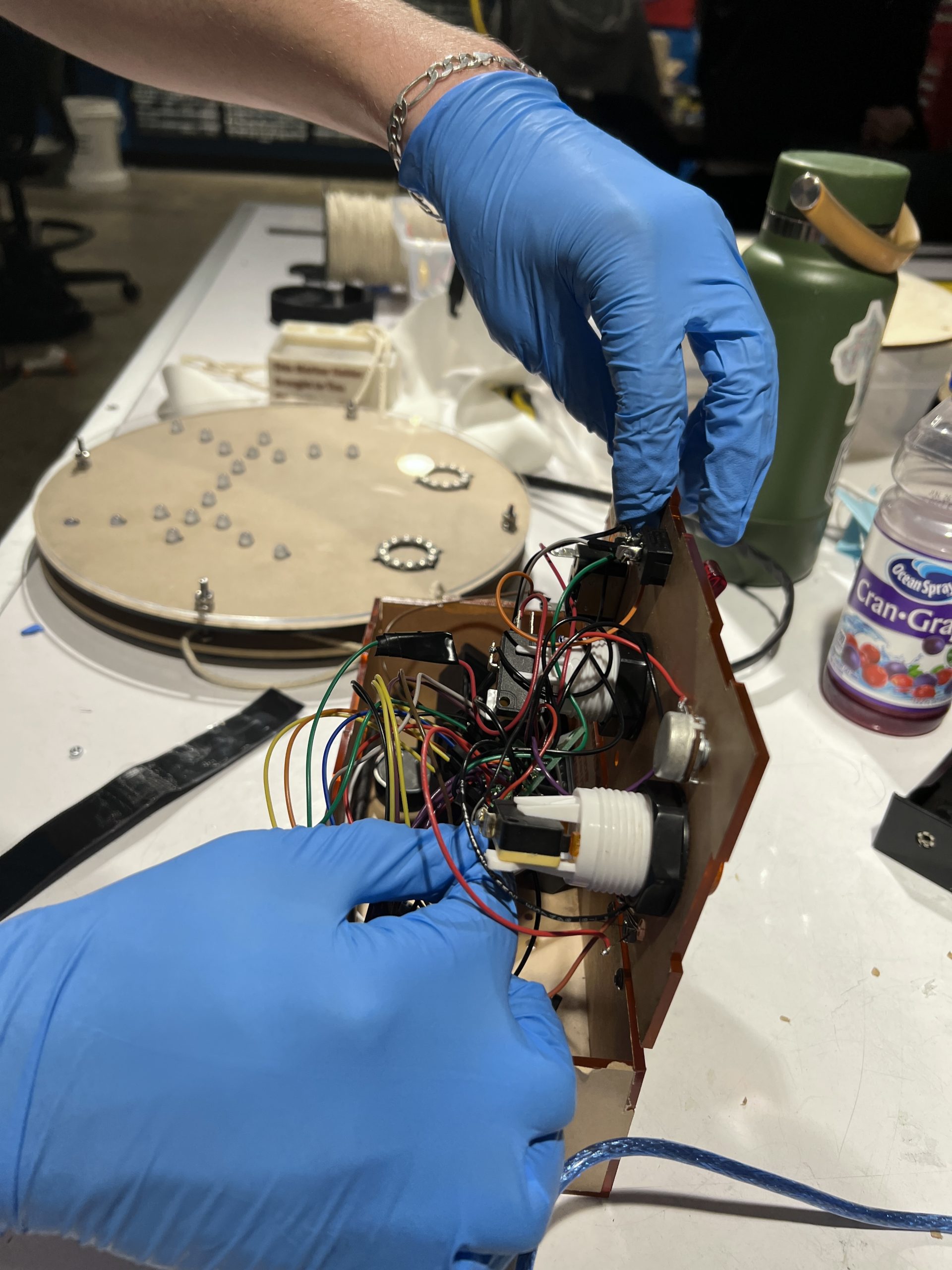
Attempting to fit all of the wiring into the final control box.
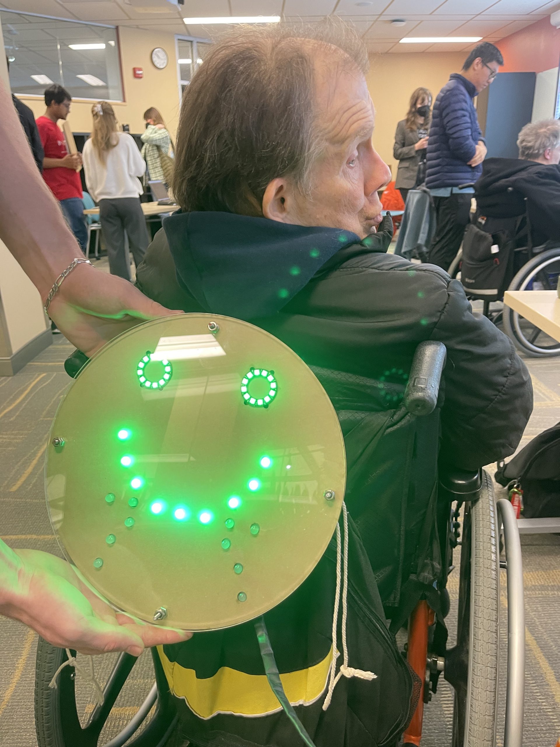
Dennis with his final emotional display (photo requested by Dennis).
To our surprise, the circuit build was one of the most challenging parts of the project. In particular, wiring together the individual LEDs for the smiles proved to be more intensive than we had originally thought. We had to plan in four individual circuits (the smile, neutral mouth, frown, and connecting middle section) as we weren’t exactly sure how to light up the individual LEDs, despite that they were addressable. Creating the four individual circuits was challenging. The first two attempts at wiring were faulty, so both had to be restarted. Then, once the circuits were finished being soldered together, they had to go into the face display, which presented a new set of problems. The LED series were incredibly finicky to work with. Often, the wrong series would light up or the lights would blink in multiple colors rather than staying the single color assigned to them in code. We figured out that a data-in line was somehow wired into a ground line group, which caused our initial round of issues. Additionally, we figured out that some of the pins of the LEDs were touching each other as they sat behind the middle faceplate, causing further disturbances within the feedback. These problems were never really even solved, the lights continuing to be finicky all the way through the presentation.
With respect to the Gantt chart, the set back caused by the problems we had with the LED series pushed back other plans, throwing off the scheduling of the rest of the chart. The laser cutting, which was intended to finish six days before the final prototype presentation, was only finished two days before. Similarly, the final assembly of the device occurred the night before the final presentation rather than the intended two days prior. A large part of our lack of speed as a group was due to unbalanced experience. For many parts along the process we became reliant upon Remy, who has far more experience with physical production of electronics, to confirm details and tasks. This, in turn, interrupted Remy’s process, creating a positive feedback loop.
Then, in a final blow for the presentation, we could not find any D batteries or AAA batteries to externally power our device. This means that we are still not sure if the device works purely off of external power, or for how long it is able to run off that external power. The process as a whole had many moments like this, where we really found ourselves at a loss. Yet despite our challenges and the final close call, the final product is one that we are proud of.
Conclusions and Lessons Learned
In reflection of our journey through this project, a few things really stood out to us.
Firstly, our final critique and feedback session had a lot of important thoughts to offer. While we were so focused on developing a product that would communicate to everyone around Dennis how he was feeling, our product was limited to giving a bold display to those behind him. While we had a small LED on the control panel that those talking with him could see, there was no larger display for those speaking or interacting with our client. One of the our critics summarized some of the general feedback for improvements quite well when that stated that the system could be improved with, “more animation, add a time-out feature, reduce size and use as necklace? Use LED strip instead of separate LEDs, brightness knob.” These features would greatly expand the functionality and usability of our product and would be our main additions for future iterations. Furthermore, a point was made that this device could be usable to any individual with some form of disability that inhibits their ability to communicate emotions, demonstrating the devices importance as a product on a grander scale. Beyond this, it seemed like our attention to detail in preserving the importance of aesthetics and cleanliness didn’t go unnoticed. The remaining feedback fell into one of the aforementioned groups of feedback, and the quote above contains elements many of the critics mentioned could be included. The advice to animate the eyes is a simple change that would not only add additional emotional complexity to the display but would also reduce power usage in our system (as it would require less total LEDs to be lit up).
Secondly, we learned a lot about creating bespoke technology, particularly for disabled people. In our initial meetings, we didn’t know how to be attentive to unspoken issues yet. For many disabled people, the core problems in their lives are beyond unsolvable for a couple students doing a semester project. More so, as even non-disabled people experience problems, they don’t think of them as problems or are unwilling to speak about things as problems. A person often doesn’t know their own issues and, if they do, to voice them is very heavy social weight. We all went into the project with the notion that our client would tell us about one of these problems, not considering that Dennis may not have problems or talk about those problems. We assumed that Dennis must have a problem that he would want fixed. So focused on trying to get Dennis to describe a problem in his life, we were barely open to offering potential problems that we saw ourselves in Dennis’ life. We are incredibly grateful to have worked with Dennis for this project and his patience with us in doing so.
In conclusion, although our final product was far from perfect, we are proud of what we made. It was an interesting concept, decently executed given our collective restraints, and, most importantly to us, it was a product that Dennis was excited about. At the end of our final presentation, he asked if we could strap it on for him and there is no better affirmation than that.
Technical
Schematic and Block Diagram
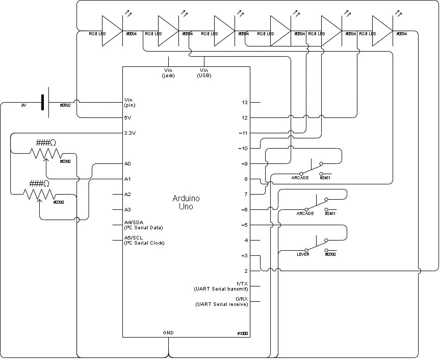
Circuit schematic for system.
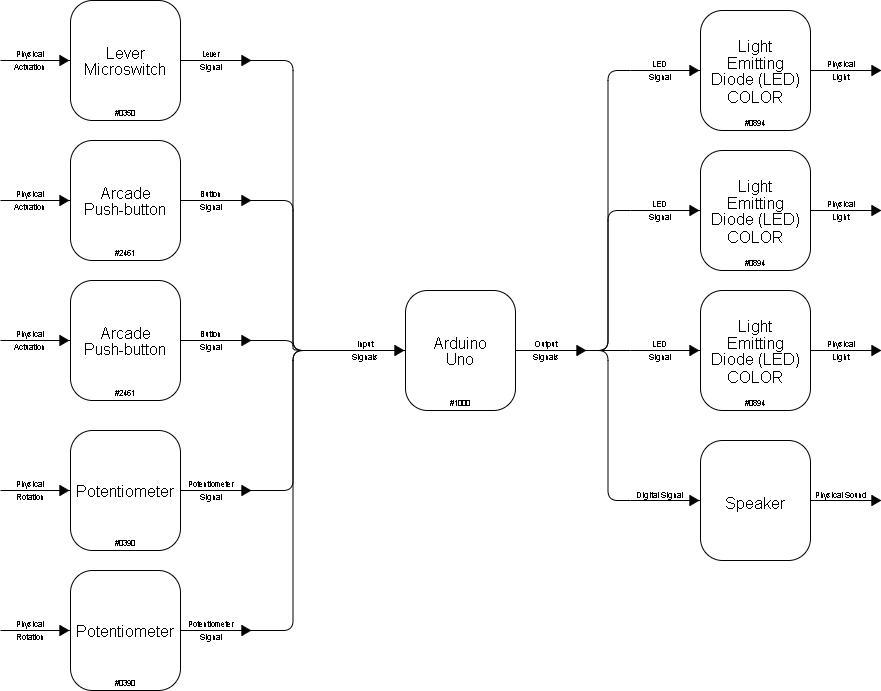
Block Diagram of the system.
Code
/*
 *  The code below is used to operate the emotional display board
 *  developed for 60-223: Intro. to Physical Computing. The wiring
 *  inputs/outputs are as shown below.
 *
 *   Pin Map:
   Pin   |  role  |   Description
   ----------------------------------------
   A0    | input  | Input readings from pot 1. For light color
   A1    | input  | Input readings from pot 2. For speaker volume
   2     | output | Controls the sound sent to the speaker
   3     | output | Writes to the neopixel ring LEDs
   5     | input  | Detects digital signal from emergency switch
   6     | input  | Detects signal to activate emotion display, button 1
   7     | input  | Detect signal to activate question display, button 2
   8     | output | Writes to inner middle mouth LEDs
   9     | output | Writes to outer middle mouth LEDs
   10    | output | Writes to LEDs showing smile
   11    | output | Writes to LEDs showing frown
   12    | output | Writes to LED displaying emotion on control panel
   5V    | output | Power supply for LEDS and buttons
   3.3V  | output | Power for remaining components
   GND   | input  | Ground for all components
 */

#include <Adafruit_NeoPixel.h>

// Define all variables and constants
const int pot1 = A0;
const int pot2 = A1;

const int switch1 = 5;
const int but1 = 6;
const int but2 = 7;
const int neoRing1 = 3;
const int three_leds = 8;
const int four_leds = 9;
const int smile = 10;
const int frown = 11;
const int emots = 12;

const int speaker = 2;

int sensOne;
int sensTwo;

int pressOne;
int pressTwo;
int pressThree;

int level = 0;
int emotion = 0;

unsigned long globTime;
unsigned long beepTime;

bool beepOn = 0;

// Define LED strips
Adafruit_NeoPixel strip = Adafruit_NeoPixel(32, neoRing1, NEO_GRB + NEO_KHZ800);
Adafruit_NeoPixel pixels(3, three_leds, NEO_GRB + NEO_KHZ800);
Adafruit_NeoPixel pixels2(4, four_leds, NEO_GRB + NEO_KHZ800);
Adafruit_NeoPixel pixels3(10, smile, NEO_GRB + NEO_KHZ800);
Adafruit_NeoPixel pixels4(11, frown, NEO_GRB + NEO_KHZ800);
Adafruit_NeoPixel pixels5(1, emots, NEO_GRB + NEO_KHZ800);

void setup() {
  Serial.begin(9600);

  // Initialize LEDs and define pin modes
  strip.begin();
  strip.setBrightness(30); //adjust brightness here
  strip.show(); // Initialize all pixels to 'off'

  pinMode(but1, INPUT_PULLUP);
  pinMode(but2, INPUT_PULLUP);
  pinMode(switch1, INPUT_PULLUP);

  pinMode(pot1, INPUT);

  pixels.begin();
  pixels2.begin();
  pixels3.begin();
  pixels4.begin();
  pixels5.begin();
}

// Below function used to write to the LEDs for question face
void lightQuestion(){
  // Insert code to light question mark
  //colorWipe(strip_mid.Color(255, 0, 255), 50);
  for(int i=0; i<3; i++) { // For each pixel...

      pixels.setPixelColor(i, pixels.Color(0, 255, 255));
      pixels.show();   // Send the updated pixel colors to the hardware.
  }

  for(int i=0; i<4; i++) { // For each pixel...

      pixels2.setPixelColor(i, pixels2.Color(0, 255, 255));
      pixels2.show();   // Send the updated pixel colors to the hardware.
  }

  for(int i=0; i<6; i++) { // For each pixel...

      pixels3.setPixelColor(i, pixels3.Color(0, 0, 0));
      pixels3.show();   // Send the updated pixel colors to the hardware.
  }

  for(int i=0; i<6; i++) { // For each pixel...

      pixels4.setPixelColor(i, pixels4.Color(0, 0, 0));
      pixels4.show();   // Send the updated pixel colors to the hardware.
  }

  colorWipe(strip.Color(255, 0, 255), 50); // Purple
}

void colorWipe(uint32_t c, uint8_t wait) {
  for(uint16_t i=0; i<strip.numPixels(); i++) {
      strip.setPixelColor(i, c);
      strip.show();
      //delay(wait);
  }
}

// Below function used to write to the LEDs for emergency face
void lightExclam(){
  // Insert code to light exclamation mark
  //colorWipe(strip_mid.Color(255, 0, 0), 50);
  for(int i=0; i<3; i++) { // For each pixel...

      pixels.setPixelColor(i, pixels.Color(0, 255, 0));
      pixels.show();   // Send the updated pixel colors to the hardware.
  }

  for(int i=0; i<4; i++) { // For each pixel...

      pixels2.setPixelColor(i, pixels2.Color(0, 0, 0));
      pixels2.show();   // Send the updated pixel colors to the hardware.
  }

  for(int i=0; i<6; i++) { // For each pixel...

      pixels3.setPixelColor(i, pixels3.Color(0, 0, 0));
      pixels3.show();   // Send the updated pixel colors to the hardware.
  }

  for(int i=0; i<6; i++) { // For each pixel...

      pixels4.setPixelColor(i, pixels4.Color(0, 255, 0));
      pixels4.show();   // Send the updated pixel colors to the hardware.
  }

  colorWipe(strip.Color(255, 0, 0), 50); // Red
}

// Initialize speaker and send sound signal
void initSound(){
  globTime = millis();

  if(abs(globTime - beepTime) >= 3000 && !beepOn){
    tone(speaker, 2000, 600);
    beepTime = globTime;
    beepOn = 1;
  }

  if(abs(globTime - beepTime) >= 1000 && beepOn){
    noTone(speaker);
    beepTime = globTime;
    beepOn = 0;
  }
}

// Level 0: emotional control lights
// Level 1: Question mark light
// Level 2: Exclamation mark and sound control
void loop() {
  if(level == 0){
    sensOne = analogRead(pot1);

    Serial.println(sensOne);

    emotion = map(sensOne, 0, 700, 0, 5);
    emotion = round(emotion);

    //Serial.println(emotion);

    lightEmotion();

    switchControls();
  }

  if(level == 1){
    lightQuestion();
    switchControls();
  }

  if(level == 2){
    lightExclam();
    // Might not need, just use potent as variable resistor to change volume instead of
    // doing in software.
    //sensTwo = analogRead(pot2);
    switchControls();
    initSound();
  }
}

// Below function used to read any changes in current mode of the system
void switchControls() {
  // insert detection for button presses to switch controls
  pressOne = digitalRead(but1);
  pressTwo = digitalRead(but2);
  pressThree = digitalRead(switch1);

  //Serial.println(level);

  if(!pressThree){
    level = 2;
  }

  if(!pressTwo && pressThree){
    level = 1;
  }

  if(!pressOne && pressThree){
    level = 0;
  }

  if(pressOne && pressTwo && pressThree && level == 2) {
    level = 0;
  }
}

// Below function used to write to the LEDs depending on current emotion
void lightEmotion() {
  if(emotion == 0){
    // light red angry
    for(int i=0; i<3; i++) { // For each pixel...

      pixels.setPixelColor(i, pixels.Color(0, 255, 0));
      pixels.show();   // Send the updated pixel colors to the hardware.
    }

    for(int i=0; i<4; i++) { // For each pixel...

      pixels2.setPixelColor(i, pixels2.Color(0, 0, 0));
      pixels2.show();   // Send the updated pixel colors to the hardware.
    }

    for(int i=0; i<6; i++) { // For each pixel...

      pixels3.setPixelColor(i, pixels3.Color(0, 0, 0));
      pixels3.show();   // Send the updated pixel colors to the hardware.
    }

    for(int i=0; i<6; i++) { // For each pixel...

      pixels4.setPixelColor(i, pixels4.Color(0, 255, 0));
      pixels4.show();   // Send the updated pixel colors to the hardware.
    }

    colorWipe(strip.Color(255, 0, 0), 50); // Red
    pixels5.setPixelColor(0, pixels5.Color(0, 255, 0));
    pixels5.show();
  }

  if(emotion == 1){
    // light orange unhappy
    //colorWipe(strip_mid.Color(255, 55, 0), 50);
    for(int i=0; i<3; i++) { // For each pixel...

      pixels.setPixelColor(i, pixels.Color(55, 255, 0));
      pixels.show();   // Send the updated pixel colors to the hardware.
    }

    for(int i=0; i<4; i++) { // For each pixel...

      pixels2.setPixelColor(i, pixels2.Color(0, 0, 0));
      pixels2.show();   // Send the updated pixel colors to the hardware.
    }

    for(int i=0; i<6; i++) { // For each pixel...

      pixels3.setPixelColor(i, pixels3.Color(0, 0, 0));
      pixels3.show();   // Send the updated pixel colors to the hardware.
    }

    for(int i=0; i<6; i++) { // For each pixel...

      pixels4.setPixelColor(i, pixels4.Color(55, 255, 0));
      pixels4.show();   // Send the updated pixel colors to the hardware.
    }

    colorWipe(strip.Color(255, 55, 0), 50); // Orange
    pixels5.setPixelColor(0, pixels5.Color(55, 255, 0));
    pixels5.show();
  }

  if(emotion == 2){
    // light yellow neutral
    //colorWipe(strip_mid.Color(255, 255, 0), 50);
    for(int i=0; i<3; i++) { // For each pixel...

      pixels.setPixelColor(i, pixels.Color(255, 255, 0));
      pixels.show();   // Send the updated pixel colors to the hardware.
    }

    for(int i=0; i<4; i++) { // For each pixel...

      pixels2.setPixelColor(i, pixels2.Color(255, 255, 0));
      pixels2.show();   // Send the updated pixel colors to the hardware.
    }

    for(int i=0; i<6; i++) { // For each pixel...

      pixels3.setPixelColor(i, pixels3.Color(0, 0, 0));
      pixels3.show();   // Send the updated pixel colors to the hardware.
    }

    for(int i=0; i<6; i++) { // For each pixel...

      pixels4.setPixelColor(i, pixels4.Color(0, 0, 0));
      pixels4.show();   // Send the updated pixel colors to the hardware.
    }

    colorWipe(strip.Color(255, 255, 0), 50); // Yellow
    pixels5.setPixelColor(0, pixels5.Color(255, 255, 0));
    pixels5.show();
  }

  if(emotion == 3){
    // light yellow-green happy
    //colorWipe(strip_mid.Color(100, 255, 0), 50);
    for(int i=0; i<3; i++) { // For each pixel...

      pixels.setPixelColor(i, pixels.Color(255, 100, 0));
      pixels.show();   // Send the updated pixel colors to the hardware.
    }

    for(int i=0; i<4; i++) { // For each pixel...

      pixels2.setPixelColor(i, pixels2.Color(0, 0, 0));
      pixels2.show();   // Send the updated pixel colors to the hardware.
    }

    for(int i=0; i<6; i++) { // For each pixel...

      pixels3.setPixelColor(i, pixels3.Color(255, 100, 0));
      pixels3.show();   // Send the updated pixel colors to the hardware.
    }

    for(int i=0; i<6; i++) { // For each pixel...

      pixels4.setPixelColor(i, pixels4.Color(0, 0, 0));
      pixels4.show();   // Send the updated pixel colors to the hardware.
    }

    colorWipe(strip.Color(100, 255, 0), 50); // Yellow-Green
    pixels5.setPixelColor(0, pixels5.Color(255, 100, 0));
    pixels5.show();
  }

  if(emotion == 4){
    // light green very happy
    //colorWipe(strip_mid.Color(0, 255, 0), 50);
    for(int i=0; i<3; i++) { // For each pixel...

      pixels.setPixelColor(i, pixels.Color(255, 0, 0));
      pixels.show();   // Send the updated pixel colors to the hardware.
    }

    for(int i=0; i<4; i++) { // For each pixel...

      pixels2.setPixelColor(i, pixels2.Color(0, 0, 0));
      pixels2.show();   // Send the updated pixel colors to the hardware.
    }

    for(int i=0; i<6; i++) { // For each pixel...

      pixels3.setPixelColor(i, pixels3.Color(255, 0, 0));
      pixels3.show();   // Send the updated pixel colors to the hardware.
    }

    for(int i=0; i<6; i++) { // For each pixel...

      pixels4.setPixelColor(i, pixels4.Color(0, 0, 0));
      pixels4.show();   // Send the updated pixel colors to the hardware.
    }

    colorWipe(strip.Color(0, 255, 0), 50); // Green
    pixels5.setPixelColor(0, pixels5.Color(255, 0, 0));
    pixels5.show();
  }
}