For our final project, our group was given the opportunity to work with a client with a disability from CLASS (Community Living And Support Services) to develop a personalized assistive device that would improve their lives in some aspect. Over the course of seven weeks, we were able to brainstorm, design, prototype, and assemble a device tailored particularly to our client’s wants and needs, Teri Owens. Specifically, drawing from her love of music which we discovered during our interview, we wanted to add onto the existing list of assistive musical instruments by creating a MIDI controller that would be controlled by certain foot movements to produce sound electronically. For more details and interview documentation with Teri, please visit this page.
What We Built
Our product is essentially a MIDI (Musical Instrument Digital Interface) controller that is controlled by different foot movements which is purposefully meant to be placed on the foot plate of our client’s wheelchair. In our case, there is a roller which is used to change the pitch of a note or the percussion instrument and two foot pedals. One of the foot pedals makes a note sound while the other makes a percussion sound. This device is then connected to a computer via USB where the user can operate on a free MIDI software site and select different tracks to change the sound that is amplified from the speakers.

Front
Side
Back
Angle
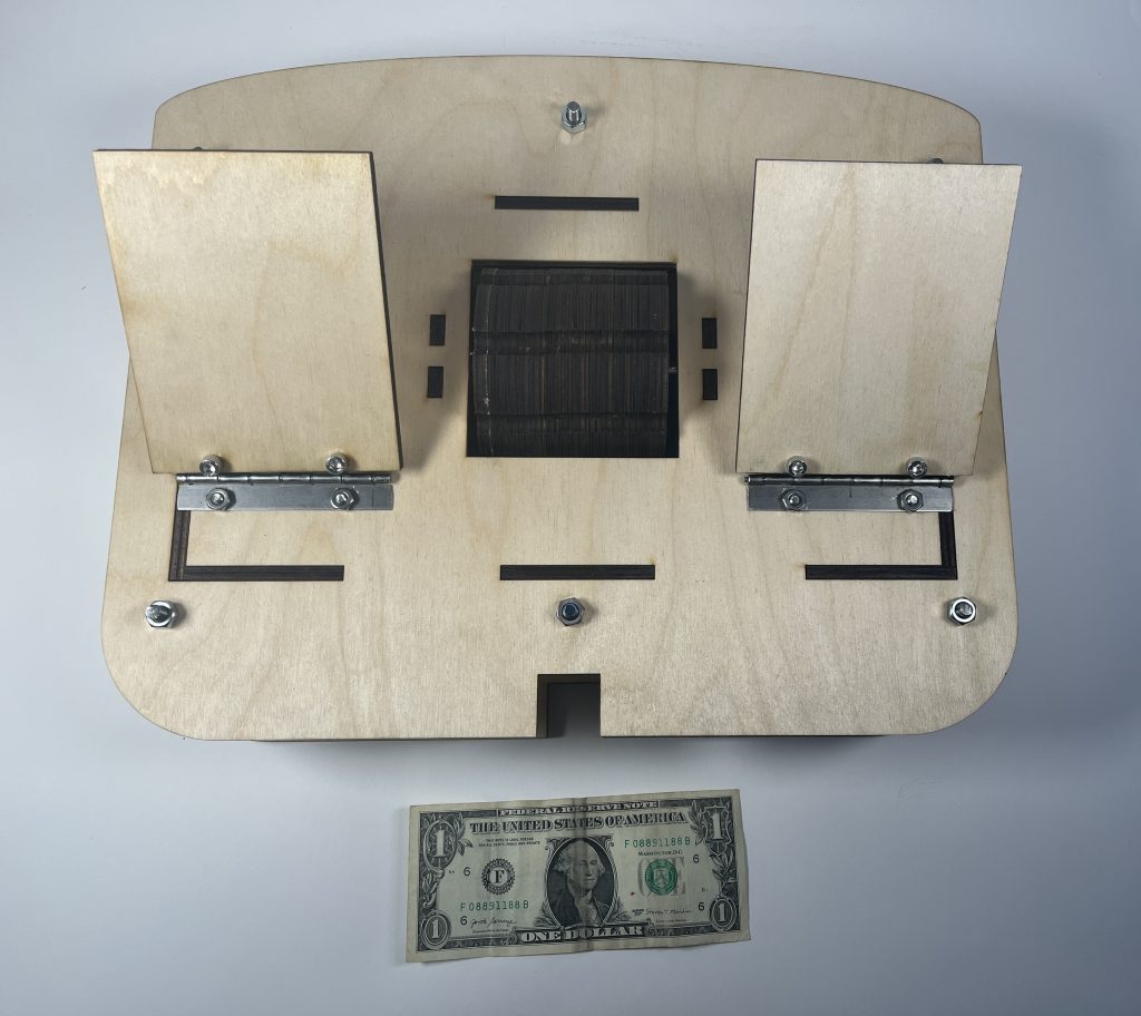
Dollar as Size Reference
Testing Our Final Design
Narrative Sketch
It is finally Friday morning, and Teri opens her eyes with excitement as she comes to the realization that today is her Spring Concert. Without waking the rest of the house by not connecting the MIDI foot controller to her tablet, she practices all the movements including tapping and rolling from memory, each one with its own particular level of precision following a specific beat. While moving her whole body to the beat, she smiles as she knows she has perfected her part of the percussion and notes just like she had practiced a million times beforehand.
Before she knows it, she is on stage in front of an audience where she is able to spot familiar faces. With a million thoughts running through her mind only thinking about her part of the concert, she plugs the USB cord into her tablet to get the MIDI controller started and selects the track: House 05. As she hears the other percussion instruments start and a five second pause, she knows it’s her turn to start playing as the other percussionist starts. By using her feet to move the roller in the direction away from her, she changes to a higher pitch. As she focuses on only stepping the right pedal, she plays the drums to the perfect and and steps on the left pedal to play the notes exactly from memory. After all her steps and rolls, she waits patiently for her next part to come up: a solo.
How We Got Here
Prototype
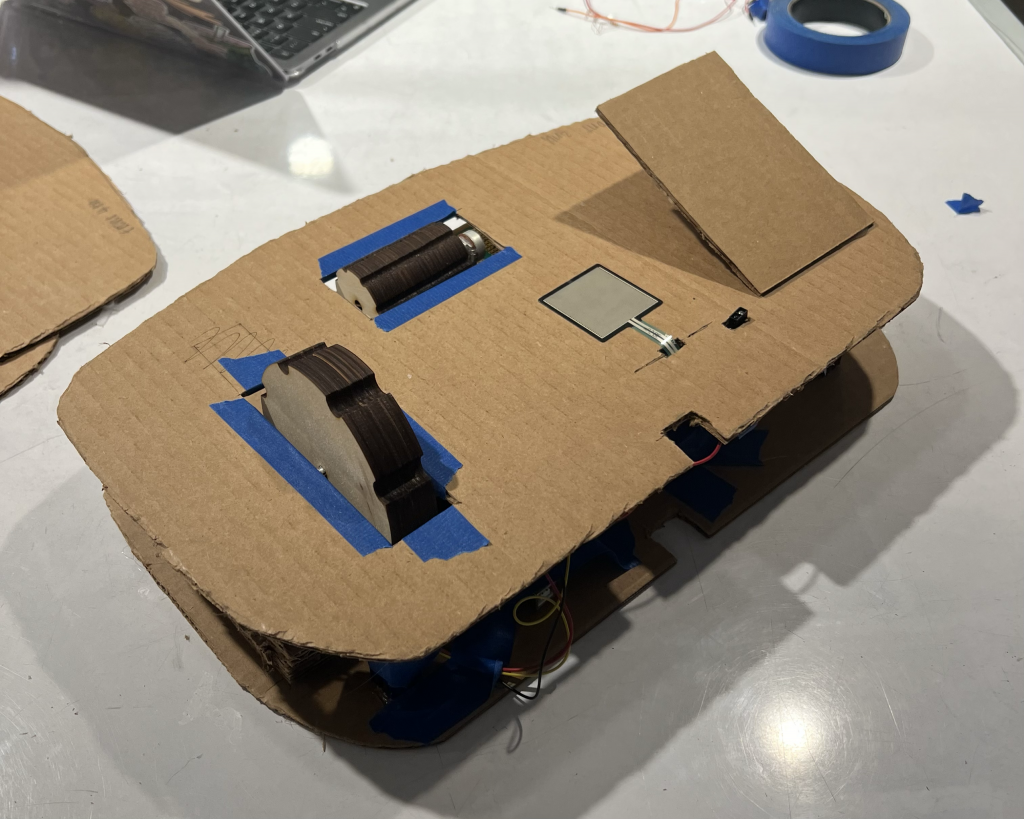
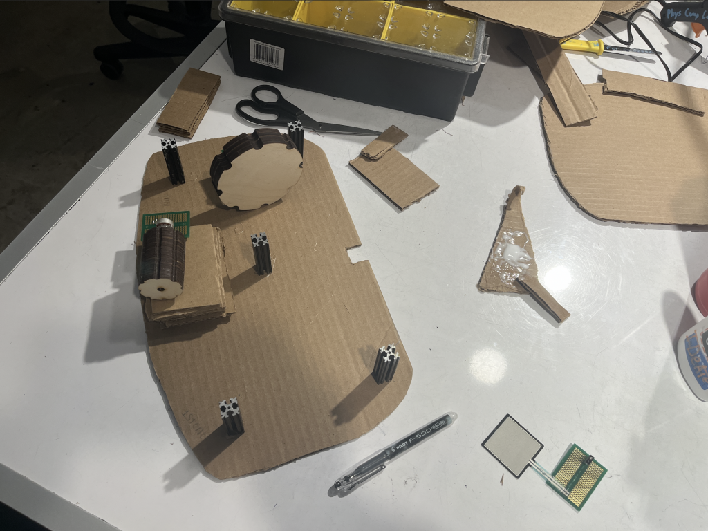
This prototype was designed to help answer the design question: How can we create another assistive musical instrument for Teri to be able to play? Our prototype was a fitted cardboard structure fitting of our client’s plate with five different components: a foot pedal, distance sensor, pressure sensor, and two differently shaped rollers of varied height and width. The cardboard structure was held up with six metal beams for stability.
Final Prototype
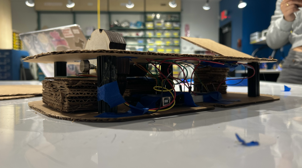
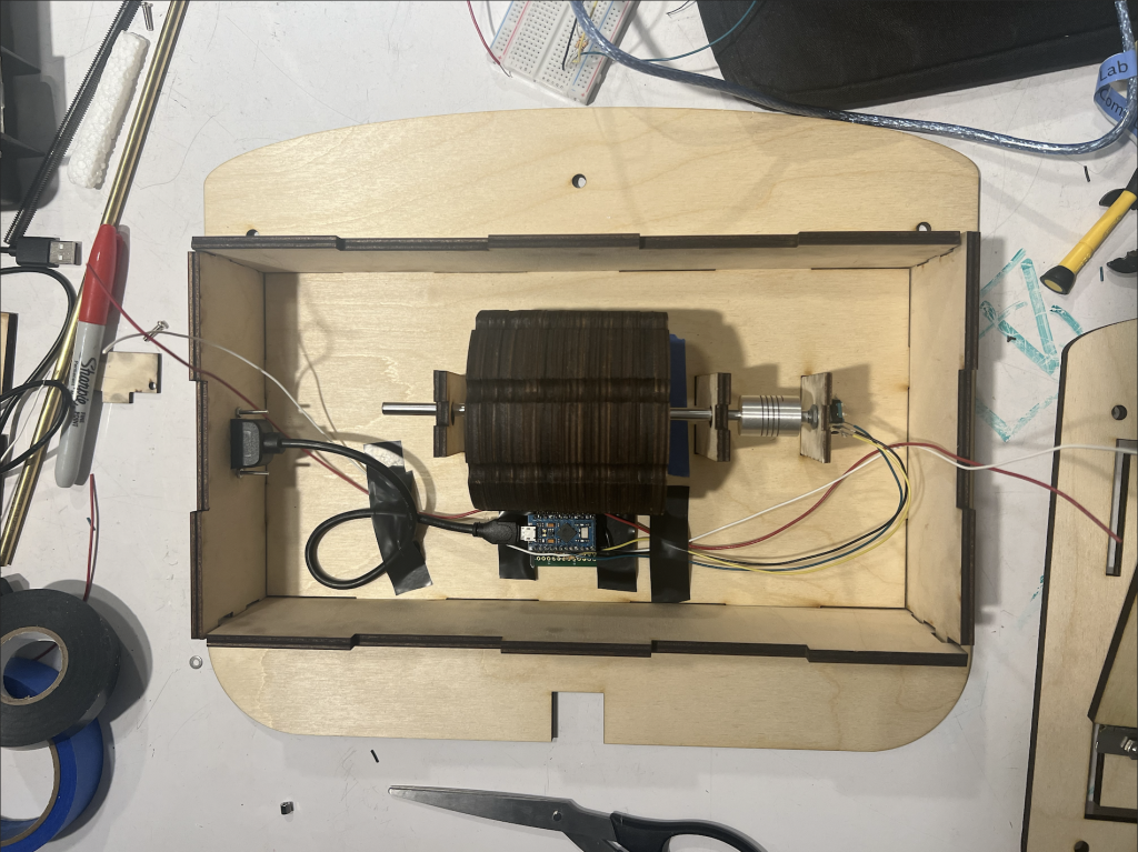
Electronics/Interior of Prototype
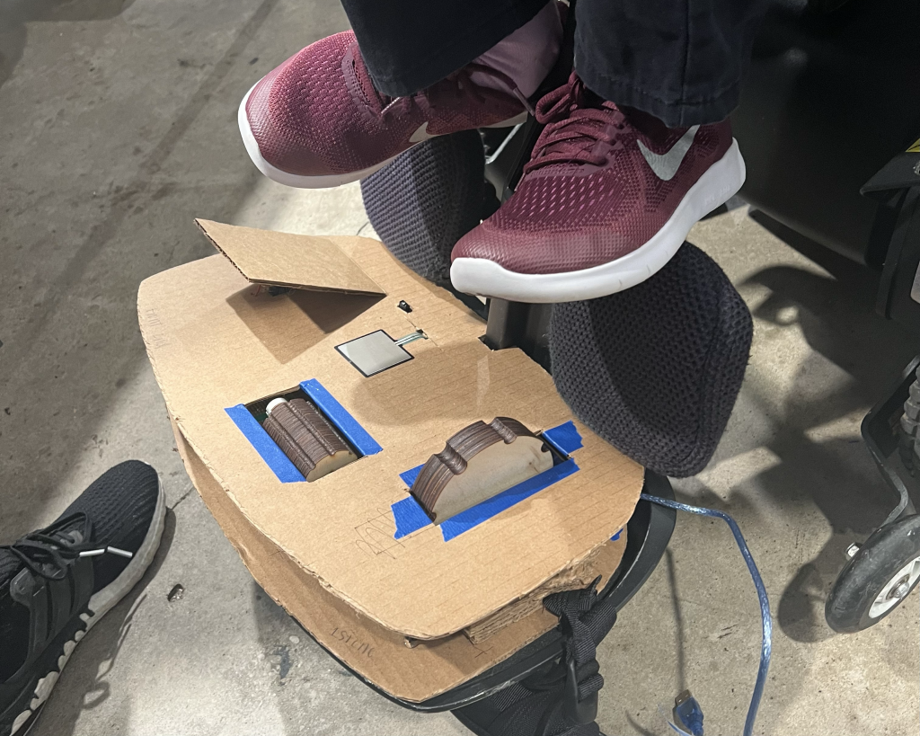
Prototype Fitted onto Teri’s Chair
Testing the Prototype
From our prototyping process, we had to keep in mind that this was simply that – a prototype. It was difficult to shift our thinking from creating a tangible product in our first attempt as we were motivated to see it come together quickly and to be able to present it to our client during the prototype critique. However, as we worked, we realized the importance of the formative critique: its purpose was to be able to simulate a real and future product to test and receive additional feedback from our client before completing the final product.
As a result, we were able to experiment with different types of foot controlled movement including a foot pedal, distance sensor, pressure sensor, and two differently structured rollers in the interest of figuring out what our client would like better and prefer on the final product. Although they were designed to not be strategically placed on the product, the purpose was to be able to have enough space to have our client test each one and see what would work best for her and what she is capable of doing. In addition, we were able to come up with a base for our product that would lie exactly on her foot plate to the most precise measurements as well as trying out different ways to make it structurally sound.
From the critique, we were able to listen to our client and incorporate her suggestions and preferences into our final design. Specifically, we were able to determine which foot movement options that Teri preferred and worked best for her. We decided on: two foot pedals, and one roller (thinner in width and greater height). We were able to visually see how much space we needed for each one and optimize the limited space we had on her foot plate as well as determining the placement of these three items based on which side Teri was more controlled in and comfortable with. We decided on having the foot pedals on the rightmost and leftmost sides and with the roller in the middle between the foot pedals. Lastly, we were able to see and test the stability of our structure. We settled on using more metal screw rods on our final product since the metal steel beams were a bit unstable. We were able to achieve all the goals we wanted during the prototype critique and answer all the questions that arose during the prototyping process, as well as make clarifications and affirm our process with our client. There were no surprises that we encountered nor was there any feedback that we did not implement.
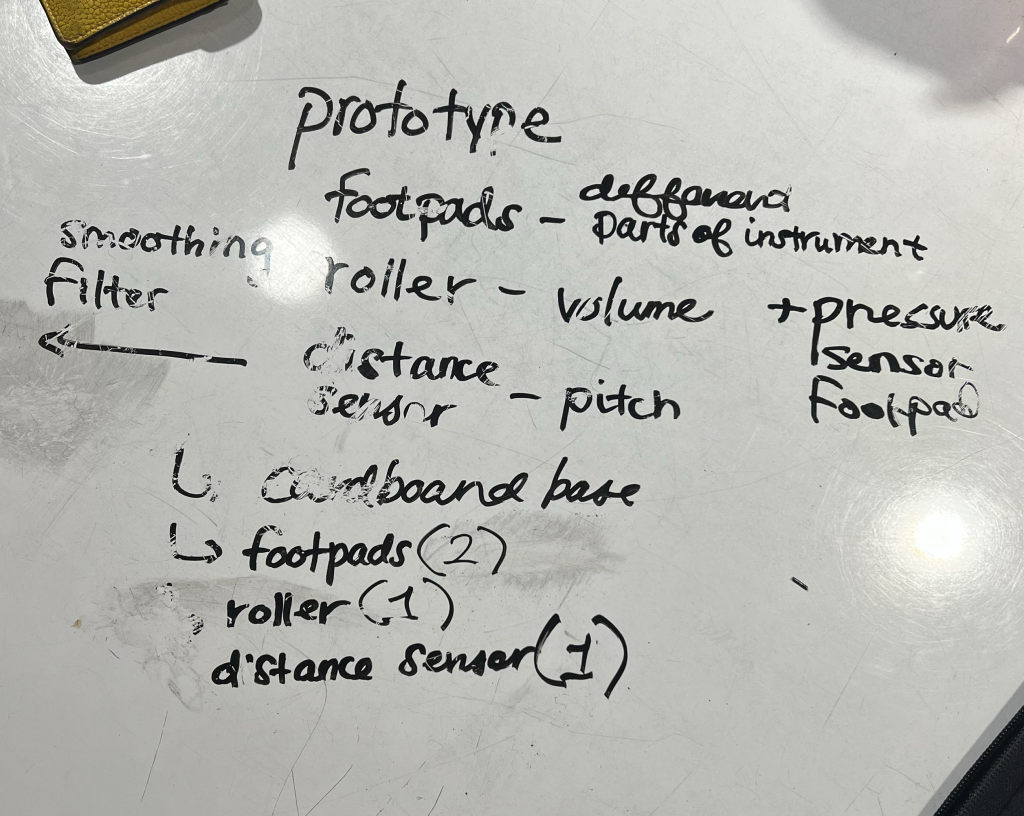
Organizing our Ideas Before Work Mode Was Engaged
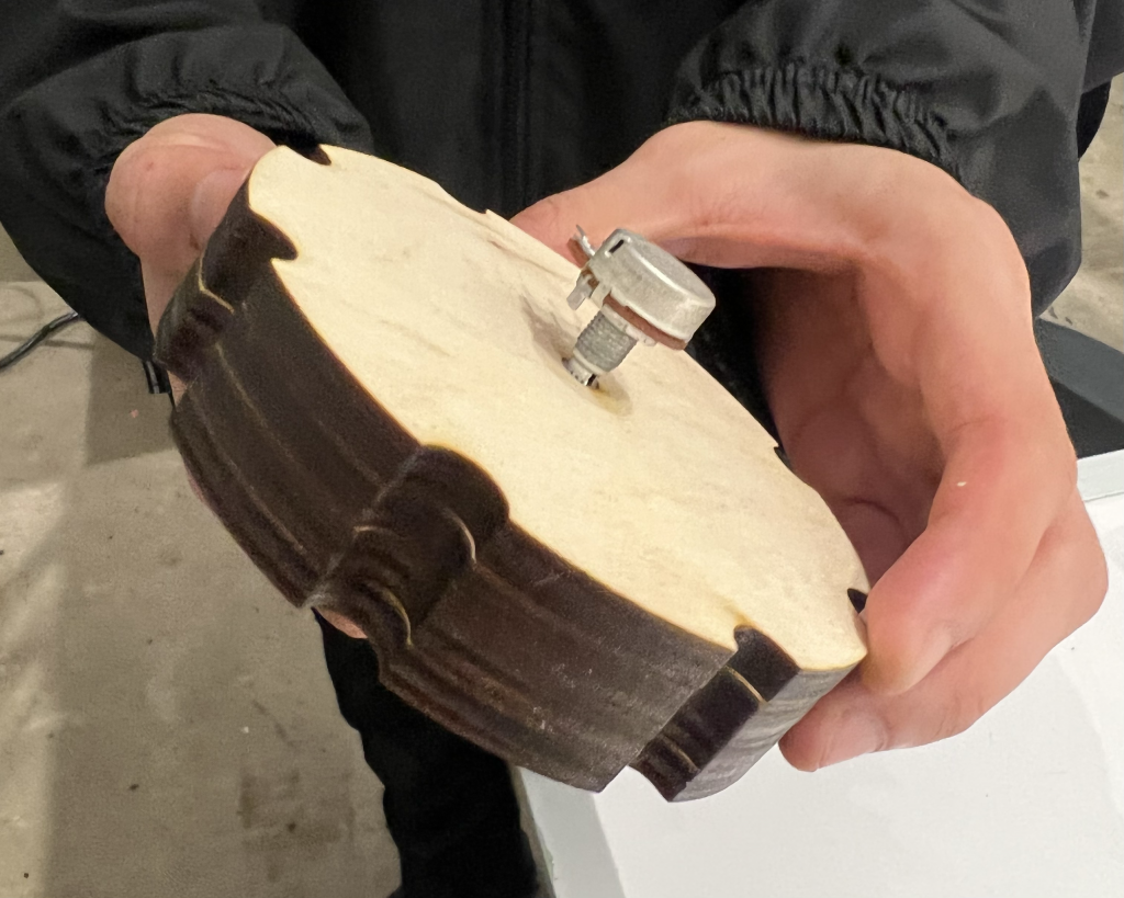
Roller from Prototype Connected to Potentiometer (Eventually Switched to Rotary Encoder)
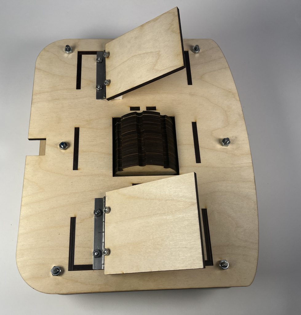
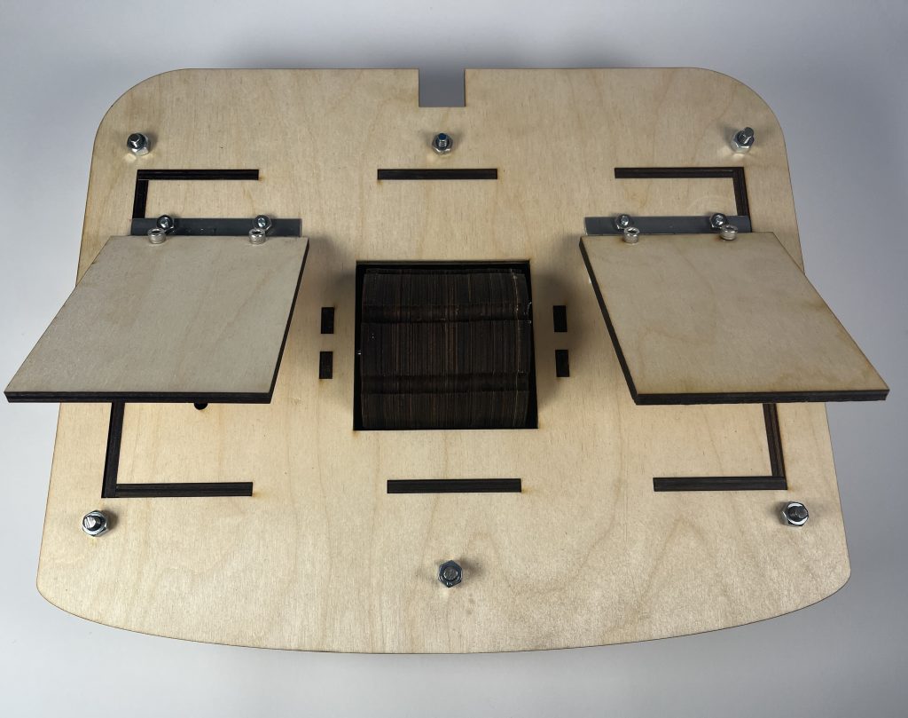
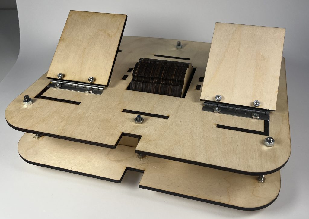
Final Prototype Assembly
Process
From our formative critique where we got Teri’s feedback on the prototype as it was, we realized we would need to ditch the pressure and distance sensors included for a simpler set of mechanisms – one large roller, which would allow her to comfortably move it back and forth with her foot, and two footpads. In an effort to make the design sturdier than our cardboard prototype (which did not hold up), we worked on creating a fully-fleshed out version of our design in Fusion360 to ensure that it was just as we imagined after laser cutting. And though we did make some last minute changes when putting together the design, through changing the material and testing it, we knew it was going to be a lot more sturdy than it was when Teri last tried it. However, our design for the roller went through a ton of changes, illustrated by our seemingly never-ending whiteboard diagrams. To ensure that it was held up, we created tabbed pieces that would hold it up, and made sure it all fit with the rotary encoder. And once it was all put together inside the box, which was protected on all sides by the interior box made, we continued to perfect our code and work on the top of the instrument. The footpads required some extra thinking when designing to ensure the footpads were situated comfortably enough for Teri to actually interact with it, connected to the Arduino below, and sturdy enough that the movement of her foot would not break the mechanism. To solve this, we created tabbed pieces that would protect the electronics from being crushed, and used foam to ensure the footpads did not come down too harshly. The design of the physical instrument was a back and forth process that required us to put ourselves in Teri’s place, asking ourselves if each part would be sturdy enough, which expanded our perspective and helped our design.
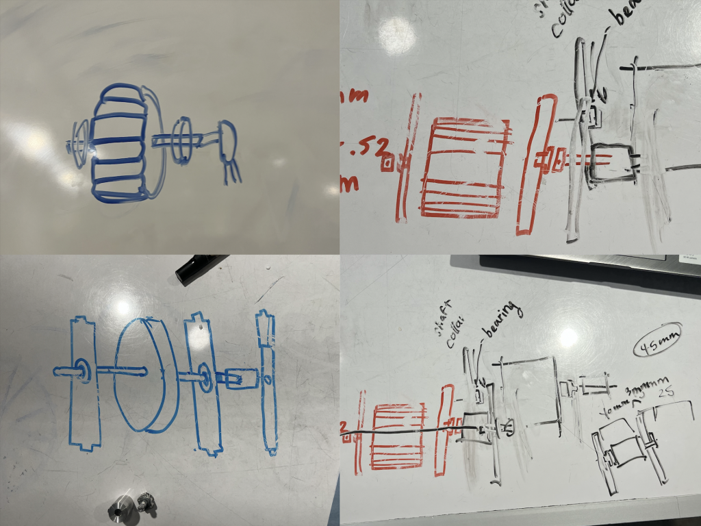
Development of the Roller Mechanism (using whiteboard tables)
Fitting the Roller Into Place
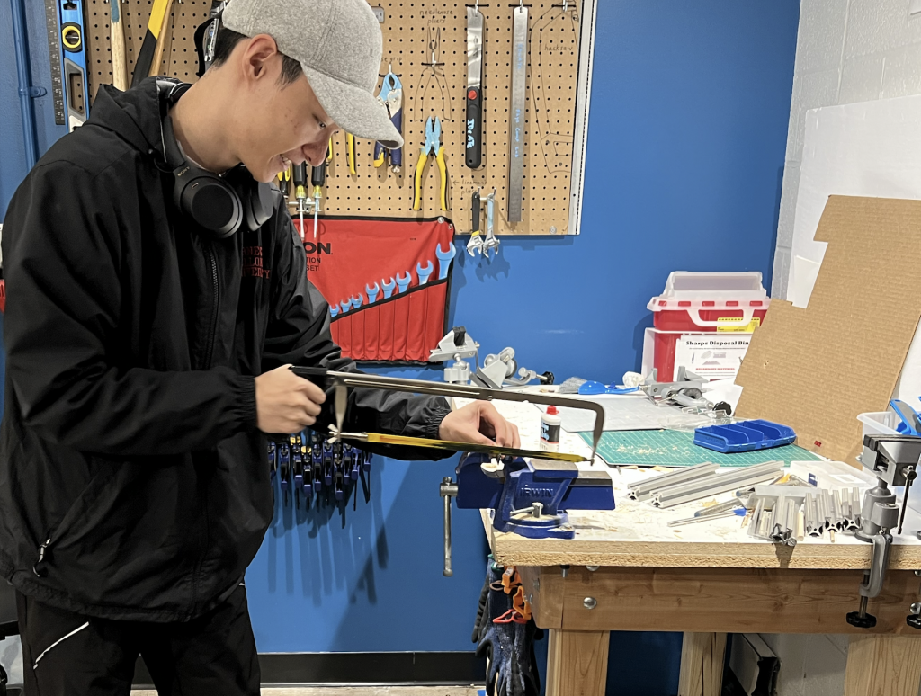
Using a Saw to Cut Hinges for Footpads
The most involved part of the process was certainly the code. Thankfully, we were able to find an online source that provided detailed instructions on how to use the Arduino Pro Micro to send out MIDI signals (linked here), which helped us greatly. However, as we implemented our code to our prototype, a few unexpected errors came out. It turned out that the instruction from the previous link was somewhat different than what we needed for our instrument. So instead of using the Pro Micro Board in Sparkfun AVR Family, we selected the original Arduino Micro from the Arduino AVR Boards list, and we were able to communicate and push command onto our board. However, after a few changes in our code, an unexpected issue occurred – the board that we had completely stopped communicating with our computers even after resetting. Thus, we made a rushed decision to change our board to the Arduino Uno, which proposed a set of new challenges. First, unlike the Pro Micro, Uno only has a serial output, which makes it incapable of transmitting MIDI signals. Therefore, outside of a few code changes, the user must install MIDI to Serial Bridge and a Virtual Loopback MIDI Port software for it to function properly. The idea of asking our client to download additional software for our product to function was suboptimal at best, so we came back to Arduino Pro Micro once more to solve the problem. While we were trying to find an alternative solution using Arduino Uno, our professor was able to successfully reset the Pro Micro that we were using and this time, with more simplified code and careful inspection of all the electronics that we had connected, our board finally started to create MIDI signals! With a bit of modification, our board was able to communicate with the online MIDI synthesizer we had picked out (due to the ease of accessibility for our client), Midi City. All of the issues that arose with the physical design and code interrupted our original Gantt chart that we had developed to keep ourselves on schedule, but ultimately, with some changes to our schedule, we were able to find enough time to complete our work before the final critique, where we got to share with Teri our final MIDI instrument design.
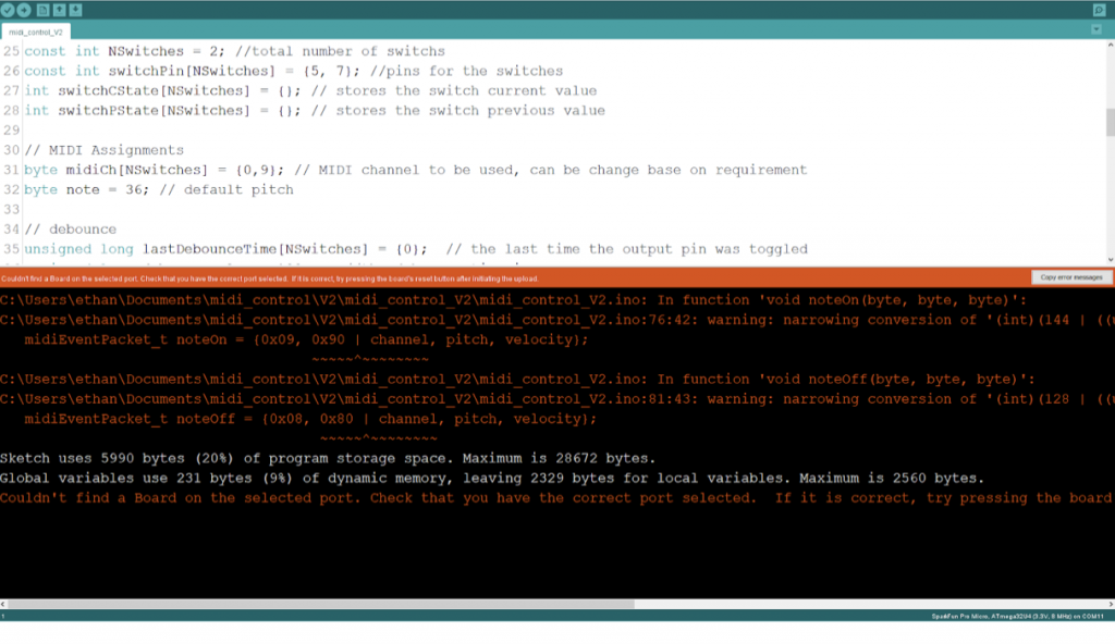
One of the Coding Errors we Encountered
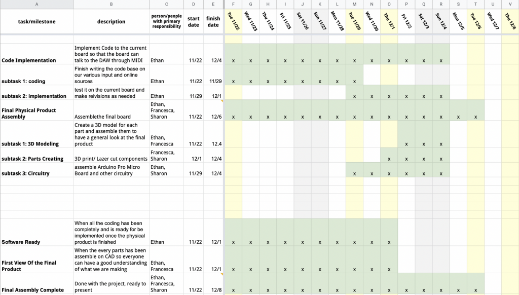
Original Gantt Chart/Work Plan
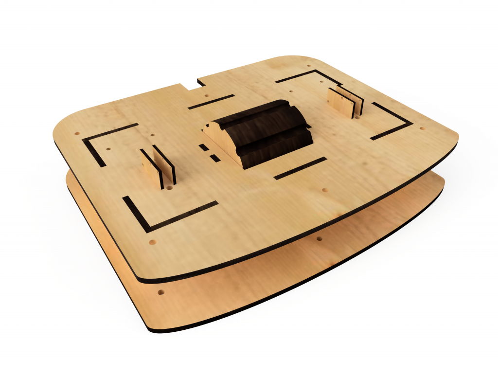
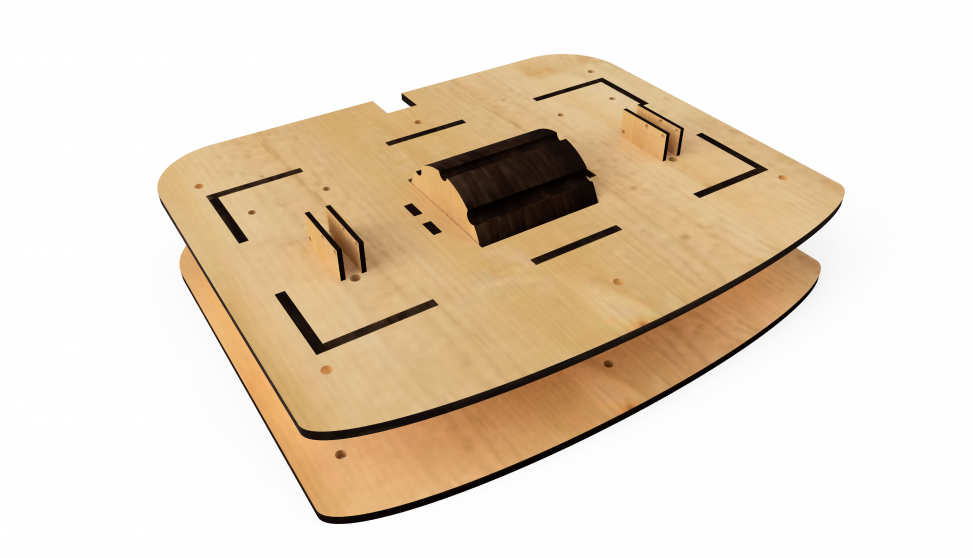
Final Design Rendering in Fusion360
Conclusions and Lessons Learned
With the passing of the final critique, our team is very proud of the progress we have made since we first met our client with no ideas in mind and transforming it into a tangible product that is specifically tailored to them. With this in mind, we were able to present our final product to our client, Teri, and have her finally try it as well while receiving feedback from others as well. With this constructive criticism we have taken into consideration and reflected upon, we were able to hear from different and fresh perspectives from individuals that would definitely make great additions and improvements to our product in the prospective future.
Specifically, one commented “[versatility in] fastening onto [a] wheel chair, [or an] application for infants,” which we believe could be a significant to our product in the future. Since this project was only tailored to our client specifically, we were narrowed in on making sure that this would fit Teri’s wheel chair as opposed to making a universal MIDI foot controller for all users. However, we agree that a more universal design would be very beneficial as it would expand the usage of this to a greater range of users. In addition, this would not only be constrained for use for those only in wheelchairs but a greater capacity than that. In addition, we could increase the target audience to children by making it more accessible or changing the format slightly so it would be easier to use in some sense or more customizable. Another comment we received concerning the design and structure of our product was “bolts are sticking up” which was something we didn’t fixate on during this process. However, if possible, we would have liked to make something was was more flat and with no hardware protruding out of the product so we definitely agree with this observation.
In addition, some other comments included “consider changing the controls—percussion, tone, etc. ” and “I think with that the computer display was better integrated with the roller – like if it looked like a mouse was hovering over the pitch/instrument that you haven’t played yet”. We agree with these comments and definitely could make this assistive instrument more useful if we were able to receive assistance from someone with a musical background to help us figure out what would be a better combination of controls. Furthermore, since we were limited to using free softwares for MIDI controllers that were on the web, a big game changer in the future for our product would be creating a software from scratch that has all these capabilities and be more user friendly and compatible with our product.
With this feedback, we were able to see what aspects we were able to excel in and some parts that could be improved in order to make this product better. Throughout the duration of the project, we were so excited and grateful to be working with Teri and not only getting to know her as a client but also as a person and learning more about what she loves to do. Having her be a part of our process was crucial to the development of our product as we were trying to make a product that she would love and have some use to in the future. From our discussions with Teri, we were able to learn so much from her and about her so that we were able to brainstorm products that she would enjoy greatly. Aside from the project, we were able to connect on similar hobbies we shared and in turn, this really helped us personalize this project more with her.
Overall, we greatly enjoyed this project and would have loved more time allocated to this project to make more than one final product and to be able to create more products and adjust accordingly to our client’s needs and feedback. We were able to connect with Teri more and it was a meaningful experience that we wouldn’t have gotten had it not been for this class. As for steps we would take differently, there isn’t really much we can say as this was a memorable experience that had exceeded our initial expectations. However, the only thing we would have liked more is more time with Teri and more time to work on this project with her and make it even better for her. It has definitely motivated us to pay more attention to our products and how it can affect the people we are making it for. We will continue to take this project in the future with us and keep what we learned in mind when working on our future projects.
Technical Details
Schematic and Block Diagram


Code
/* Foot controlled MIDI Instrument
 *
 * The following code is written to interpret the input that the Arduino Pro Micro takes and turn it into a MIDI signal.
 * which will be sent through the USB port.
 *
 * Basic function: The system currently consists of two switches and one rotary encoder.
 * When a switch is being actuated, a play signal is sent through the USB port as a MIDI signal
 * When the rotary encoder receives inputs on rotation, the pitch is changed accordingly.
 *
 * Pin Mapping:
 * Arduino Pin  /  Role   /   Description
 * 2              Input     receive data from the rotary encoder
 * 3              Input     receive data from the rotary encoder
 * 5              Input     left foot pad/switches
 * 7              Input     right foot pad/switches
 *
 * Ethan Hu, Sharon Li, Francesca Menendez, 2022
 *
 * Referenced from Gustavo Silveira and Dolce Wang
 */
#include "MIDIUSB.h"
#include <Encoder.h>

// SWITCHES
const int NSwitches = 2; //total number of switchs
const int switchPin[NSwitches] = {5, 7}; //pins for the switches
int switchCState[NSwitches] = {}; // stores the switch current value
int switchPState[NSwitches] = {}; // stores the switch previous value

// MIDI Assignments
byte midiCh[NSwitches] = {0,9}; // MIDI channel to be used, can be change base on requirement
byte note = 36; // default pitch

// debounce
unsigned long lastDebounceTime[NSwitches] = {0};  // the last time the output pin was toggled
unsigned long debounceDelay = 100;    //the debounce time in ms

// Rotary Encoder
Encoder knob(2, 3);

void setup() {
  // Initialize buttons with pull up resistors
  for (int i = 0; i < NSwitches; i++) {
    pinMode(switchPin[i], INPUT_PULLUP);
  }
}

void loop() {
  for (int i = 0; i < NSwitches; i++) {
    switchCState[i] = digitalRead(switchPin[i]);
    // checking debounce to avoid accidental double tap
    if ((millis() - lastDebounceTime[i]) > debounceDelay) {
      if (switchPState[i] != switchCState[i]) {
        lastDebounceTime[i] = millis();
        // changing pitch based on data from the rotary encoder
        note=int(knob.read()/2)+36;
        if (switchCState[i] == LOW) {
          // Sends the MIDI note ON
          noteOn(midiCh[i], note, 127);  // channel, note, velocity
          MidiUSB.flush();
        }
        else {
          // Sends the MIDI note OFF by 0 velocity
          noteOn(midiCh[i], note, 0);  // channel, note, velocity
          MidiUSB.flush();

        }
        switchPState[i] = switchCState[i];
      }
    }
  }
}

// Arduino MIDI functions MIDIUSB Library
void noteOn(byte channel, byte pitch, byte velocity) {
  midiEventPacket_t noteOn = {0x09, 0x90 | channel, pitch, velocity};
  MidiUSB.sendMIDI(noteOn);
}

void noteOff(byte channel, byte pitch, byte velocity) {
  midiEventPacket_t noteOff = {0x08, 0x80 | channel, pitch, velocity};
  MidiUSB.sendMIDI(noteOff);
}