Introduction:
We are students at Carnegie Mellon University taking a class in physical computing, a project-based course in which we learn the basic skills in programming and electronics to build simple interactive devices. Throughout this course and each project, we have been challenged to raise the bar and use our newfound knowledge to create fun, interactive, and creative devices. Our current and final project challenges us to make a device that would benefit not ourselves but someone else. We were assigned to meet with Joseph, an older gentlemen from the Pittsburgh community, and to create a device that would somehow benefit his life. The device doesn’t need to be anything grand or hold commercial value, it is simply specifically designed to help out Joseph by solving a troublesome aspect of his life. Our group, the Dog-Loving Duo, consisting of Kristie and Logan, first met with Joseph at his apartment in downtown Pittsburgh on Friday, March 30 to learn about his life and decide on what to build. From there, we had a little less than two weeks to build a prototype design to present to Joseph to get his feedback. After that, we had over three weeks to create our final project, which will be given to Joseph. This post is the documentation of last three weeks of work and describes how we arrived at our final product from our prototype.
If you want more information on our initial meeting with Joseph, click here
If you want more information on our initial prototype, click here
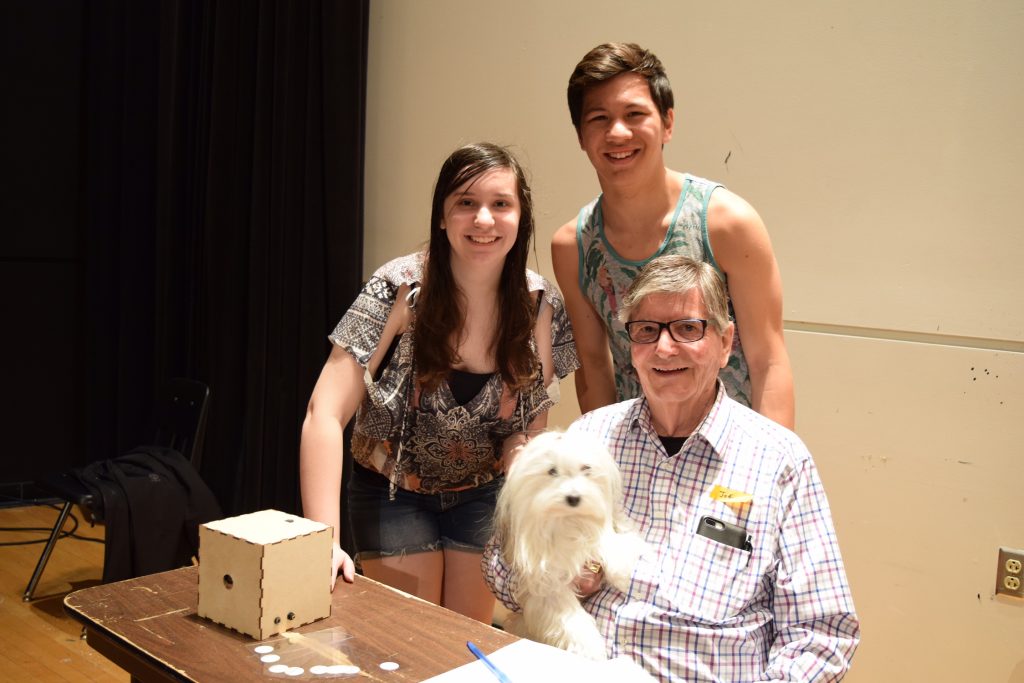
Group photo of our group, the Dog-Loving Duo with Joseph and our device
What we built:
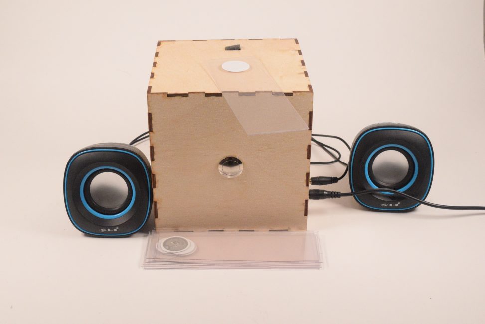
Our device is designed to help you keep track of where you last left off in a book. Each book you are reading will have a special bookmark we created inside of it. When you open the book to read, you take the bookmark out and move it over the top of our box and a short recording will play from whatever speakers or headphones you attach to the box. This recording will be a previously recorded summary of what last happened in the book. After you are done reading, you click and hold the record button for however long you wish to record a new summary of what happened. This new summary will be recorded over your previous one. After that, you place the bookmark back inside the book until the next time you start reading. In short, our device will play back a recording of what last happened in the book you are reading, so as to refresh your memory and help you keep track of what’s happening in multiple books.
Overall View of Book Reminder along with the 10 Bookmarks
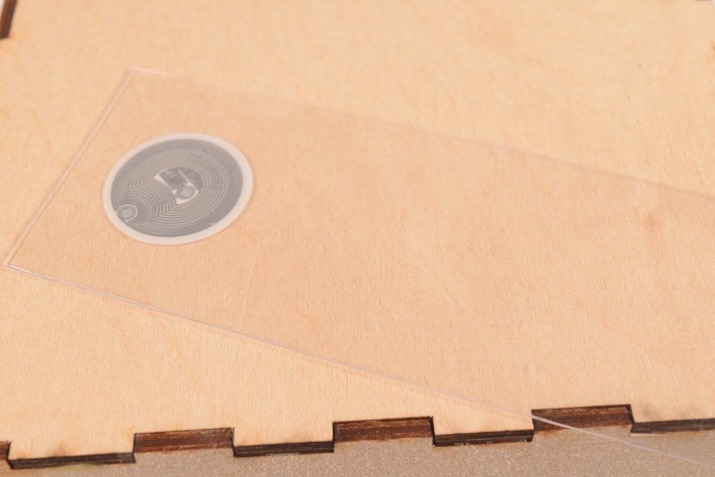
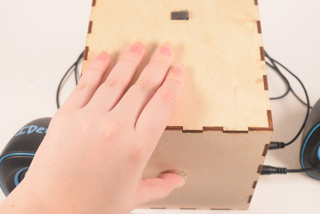
Close Up of Individual Bookmark placed on top of the Box
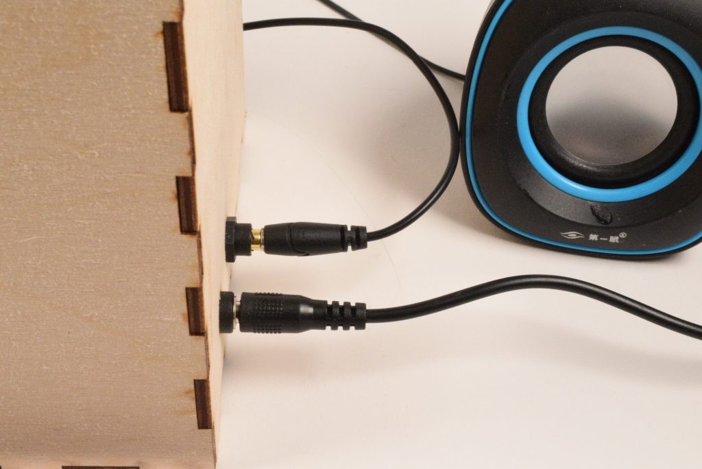
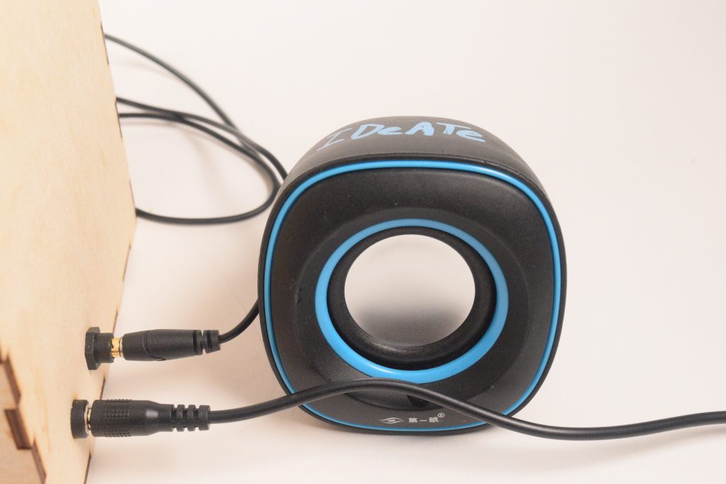
Close Up of Jacks: the jack closest to you in the photo is the one for power and the jack further away is the one that is connected to the speaker seen in the photo
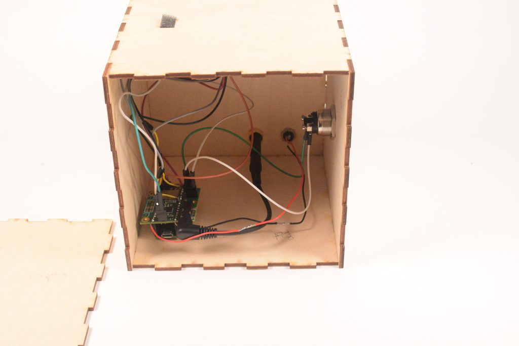
Look into the Hidden Electronic of the box that can’t normally be seen when left side is attached
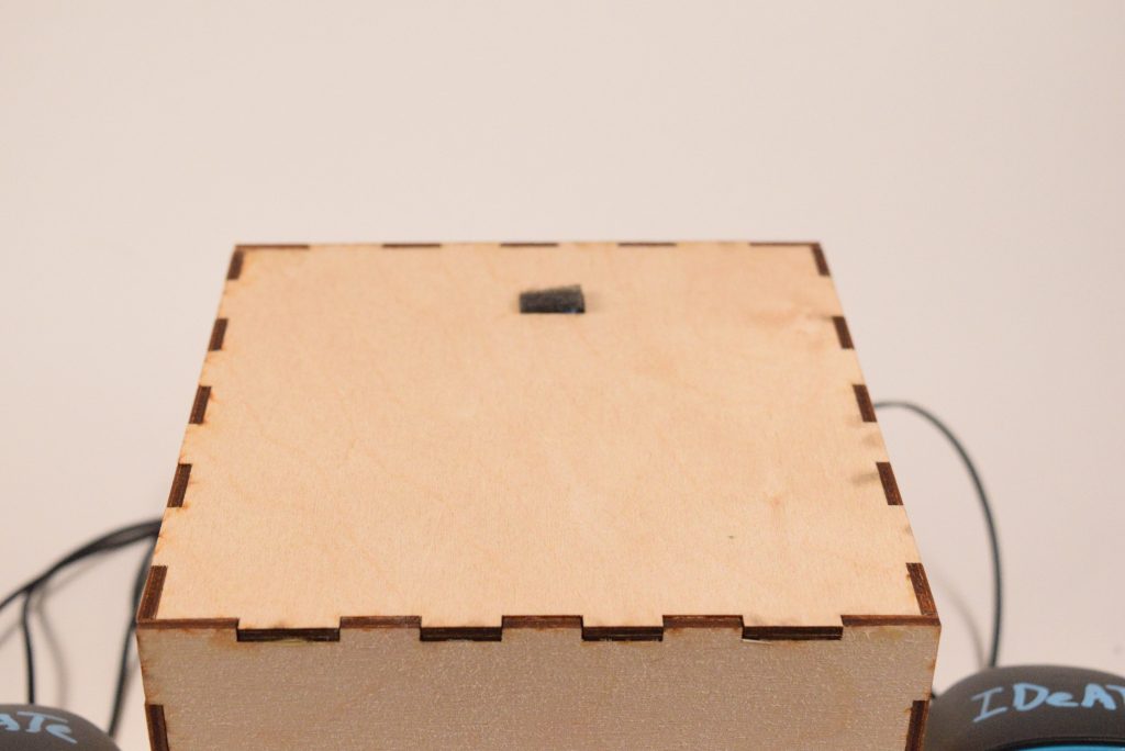
Close Up of Microphone on top of Box
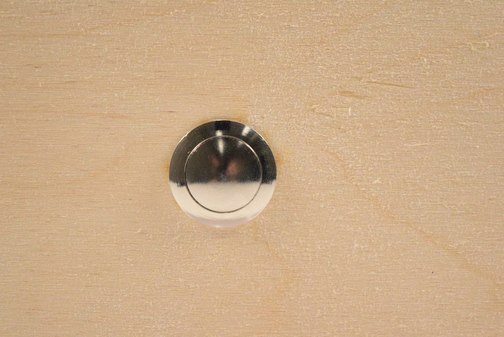
Close up of Record Button on front of Box
Using the Book Reminder:

Place bookmark on top of the box
Listen to previous recorded summary
Press and hold button as well as speak into mic on top of the box for new recording
Before his three monthly book club meetings, Joseph needs to read three different books. He picks up the first book he needs to read, “The Great Gatsby,” and opens up to where he last left off. He takes out the bookmark inside the book, places it over top of the Book Reminder, and listens to his previous recorded summary of what happened. After reading for a few hours, he places the bookmark back inside the book and prepares to record a new summary. He holds down the record button on the front of the box and speaks into the microphone on top of the box describing the events that just occurred. He describes how Tom is cheating on Daisy with a married women as well as the great metaphors he read.
A few days later, Joseph decides to continue reading the book for his other book club, “Pride and Prejudice.” Just like before, he opens up to where he last left off and listens to his previous recorded summary. After reading for awhile, he places the bookmark back inside the book and records a new summary. Thankfully, the Book Reminder keeps track of all the different books Joseph is reading and helps remind him of what last happened in his three different books.
How we got here:
From this previous prototype:
Initial prototype design
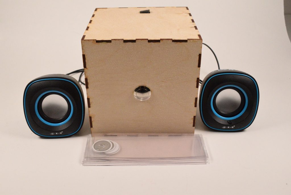
to our new and a lot nicer final project:
Final Book Reminder
After our previous prototype, we had a lot of work to do. First instead of using an Arduino, we decided to switch to using a Teensy, a more advanced electronic that is better suited for doing audio recording. Therefore, we did some research into using a Teensy for audio recording. After looking through multiple websites, we found one that was very helpful that discussed using a Teensy and an Audio Shield for recording. I also met with an IDeATe professor named Jesse, who is skilled in doing audio recording, to ask for his recommendation for a microphone. Therefore, we needed to order a bunch of new parts, so we went to Amazon and ordered: a Teensy 3.5, the audio shield recommended by the website, a 3.5 mm jack to be used as a plug in for speakers, and a MEMS microphone that was recommended by Jesse. As we were waiting for our new parts, we decided to plan our design for the box as you can see in the photo below.
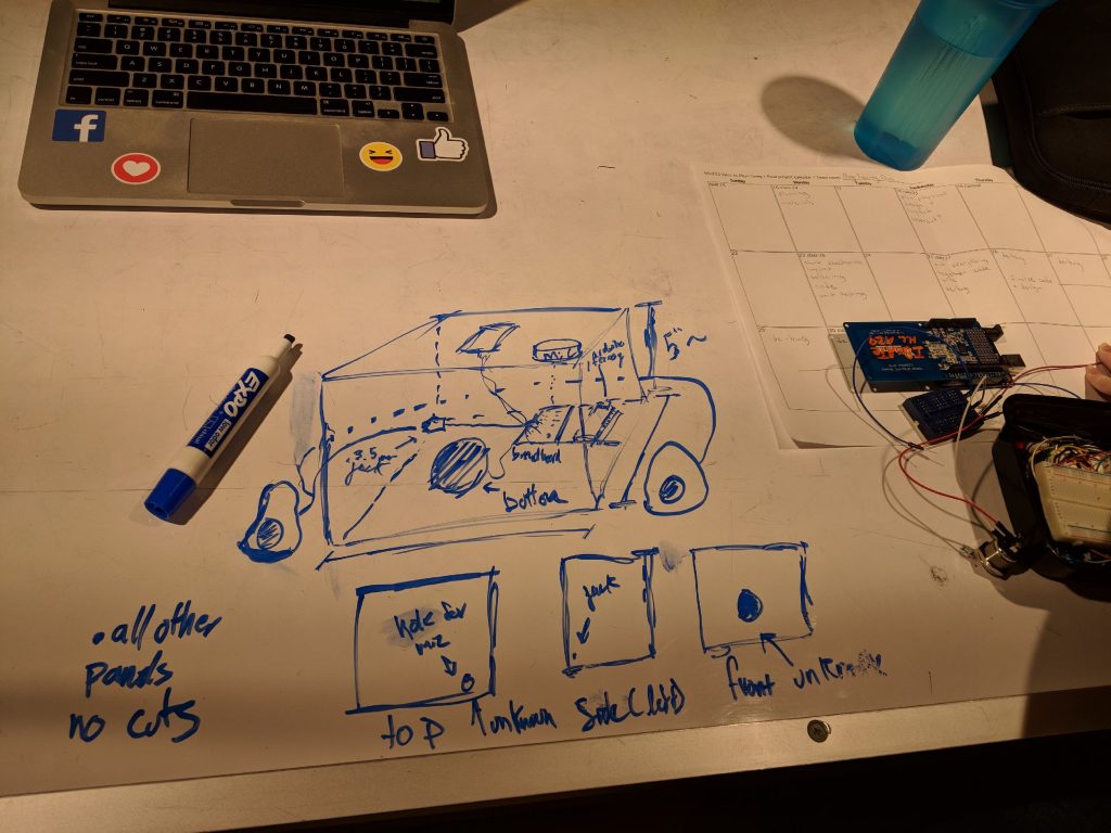
Initial Design for Final Box
After our new parts arrived, we needed to do a lot of soldering. First, we needed to solder the Teensy with male pins and the Audio Shield with female pins. After that, we also needed to solder the RFID tag reader and the MEMS mic.
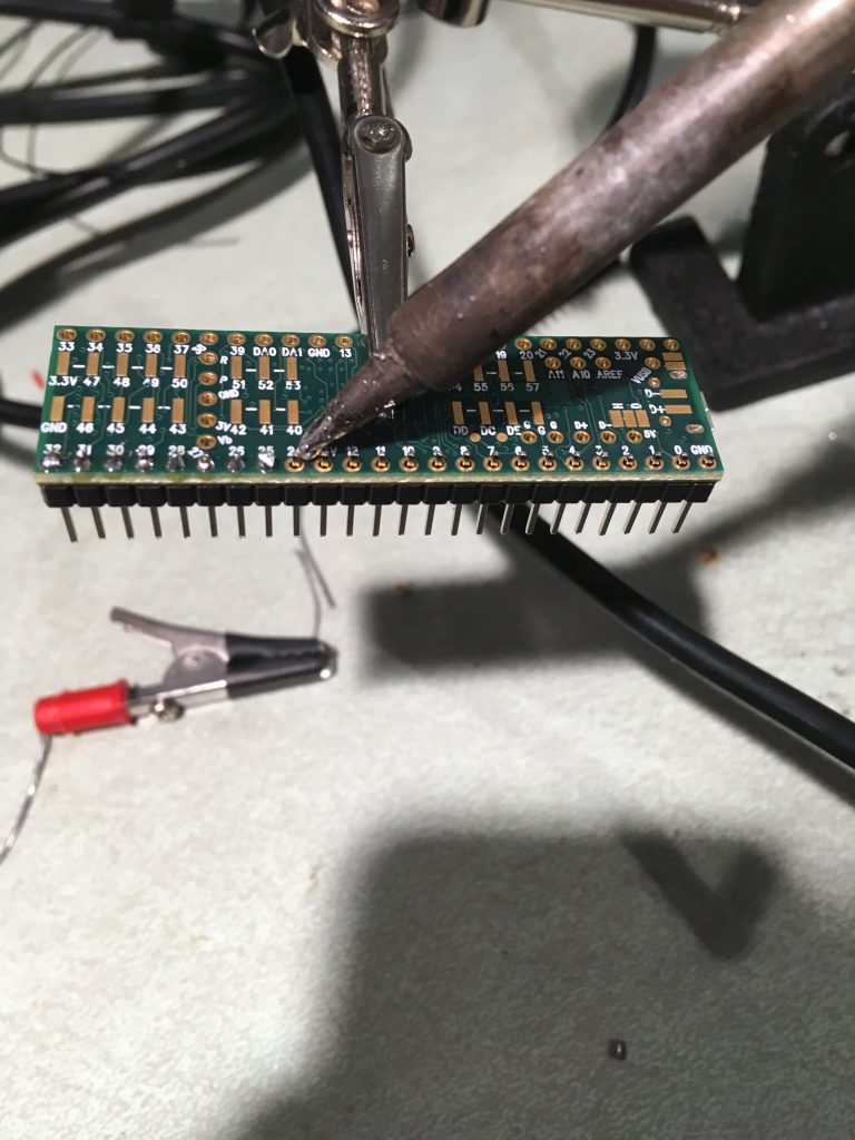
Soldering Teensy
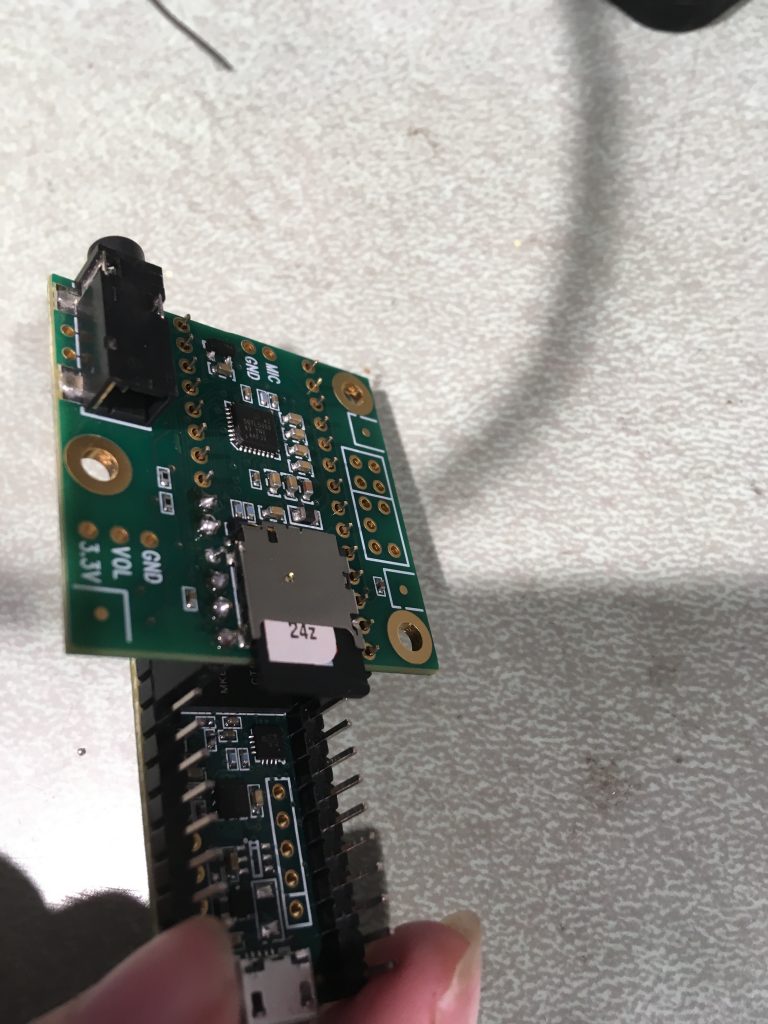
Soldering Audio Shield
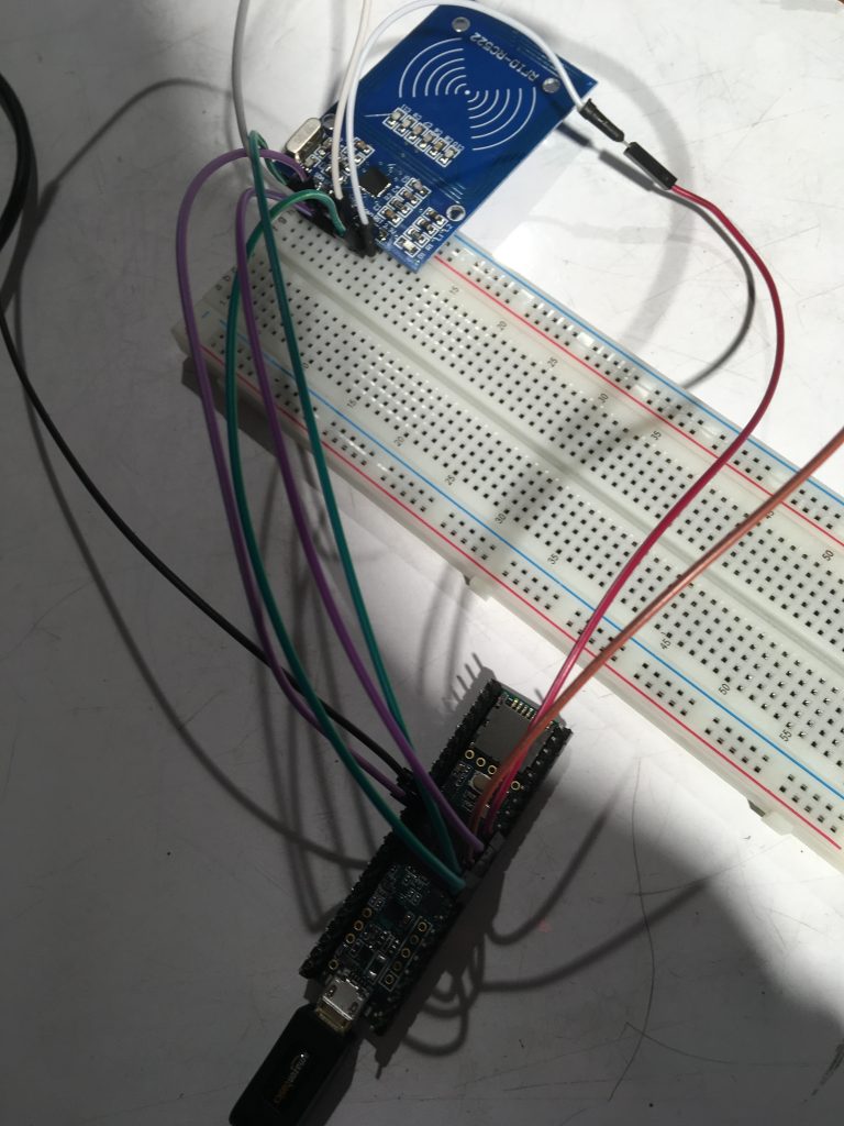
After, everything was soldered, we needed to test each part individually to make sure they all worked. The first part we wanted to test was the RFID tag reader since this part gave us the most trouble in our previous prototype. Therefore, we used a code from the library of the RC522 RFID tag reader and wired it to an Arduino to make sure it worked (see photo below). Unfortunately, this took time because the library was not great so we asked one of our friends for their code that worked when they previously used the same RFID tag reader. After editing their code, we finally got it working.
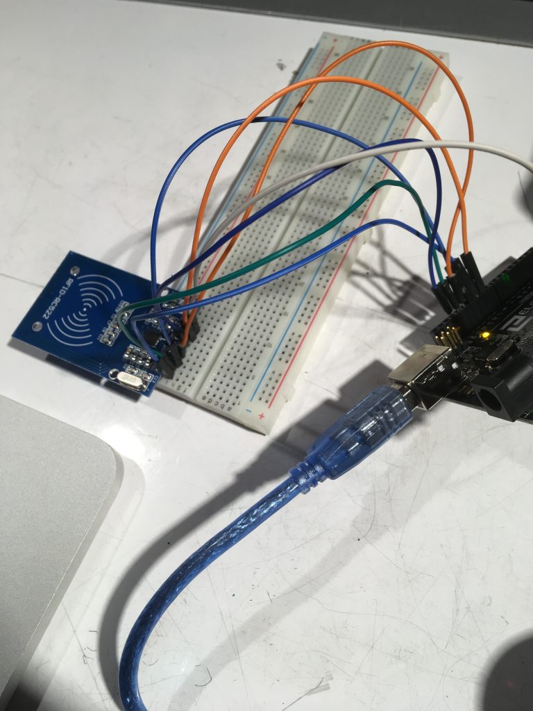
Testing RFID reader with Arduino
Next, we needed to test if the RFID tag reader could still read tags through wood, so we could be sure it could work inside our wooden box.
Testing to make sure the RFID tag reader can read tags through plywood
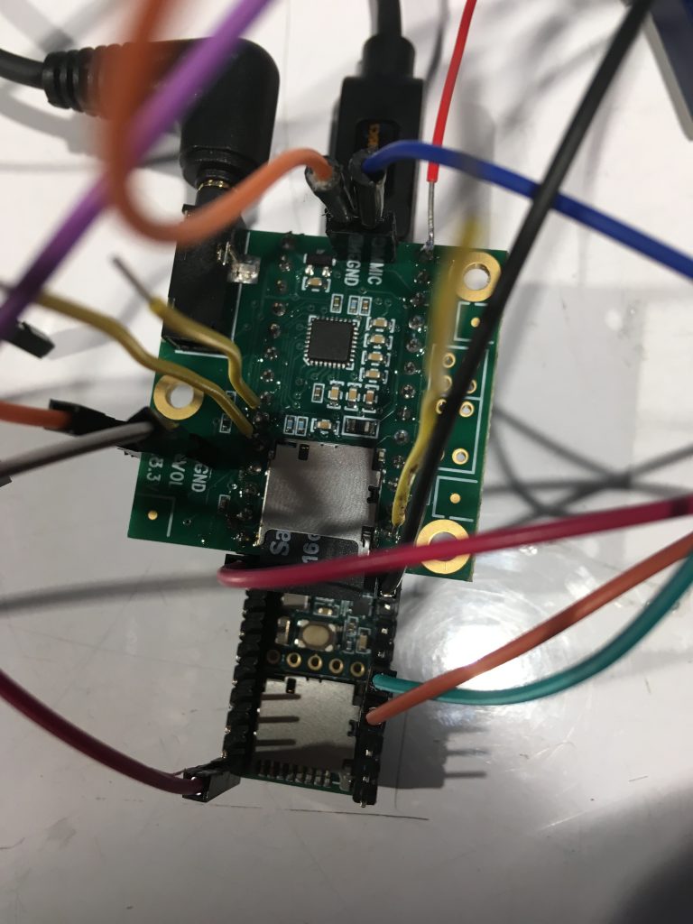
After it successfully read tags through wood multiple times, we needed to make sure the RFID tag reader was compatible with the teensy (see photo below).
Testing RFID tag reader with Teensy
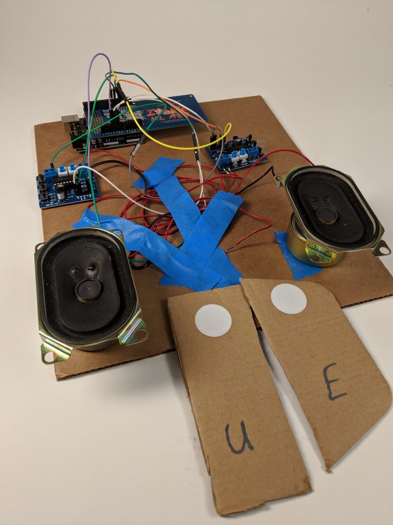
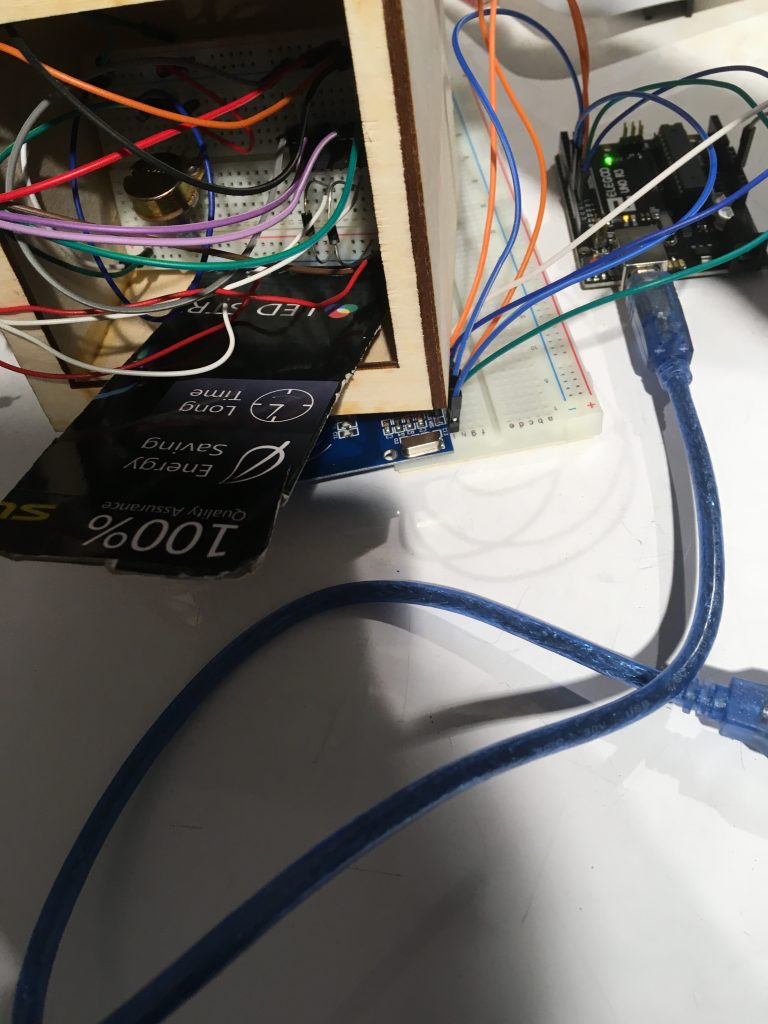
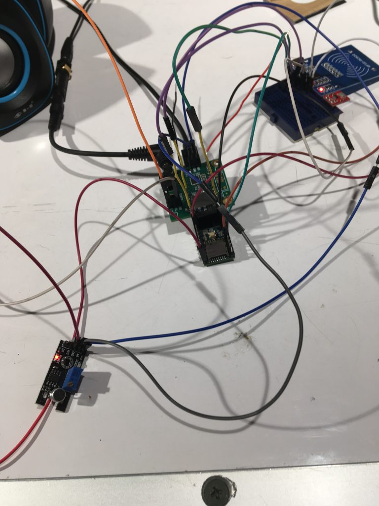
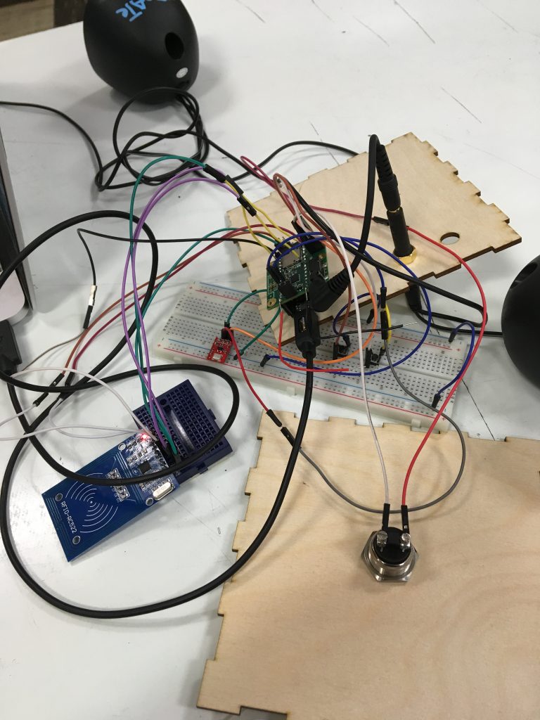
After successfully getting the RFID tag reader to work with the Teensy, we needed to make sure the audio shield worked, which it did. The next step was to check if everything worked together, so we wrote the code for everything and wired it all (see photo below).
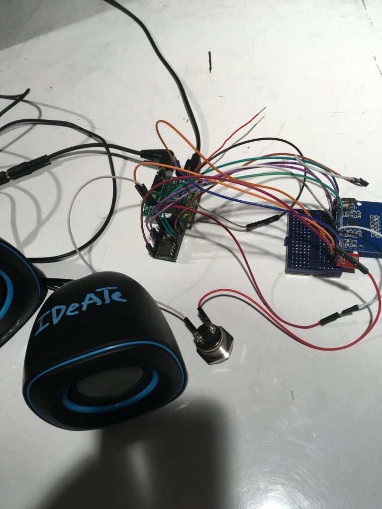
Testing Audio Shield, Microphone, and RFID Reader all together
Unfortunately, the audio shield and RFID tag reader weren’t working together since they required that you use the same pins for MISO, MOSI, and SCK. Therefore, to fix this problem, we need to solder wires coming from the audio shield at those pins.
Soldered three wires on audio shield that needed to be used with the RFID reader
Finally, after fixing this. we could test everything together. We also decided to test out a new microphone to see if that worked better than the MEMS mic (see photo). Like expected, this microphone didn’t work better, so we continued using the MEMS microphone.
Testing new microphone to see if it works better
Next, we needed to lasercut a box to place our electronics in. This box was to be made according to our initial design with a hole for the button in the front, two holes for the jacks on the side, and a hole on the top so the microphone recorded better. To make the box, we used a website called MakerCase and then SolidWorks to draw the holes into our box design. Next, we needed to mount the button and jacks onto the box.
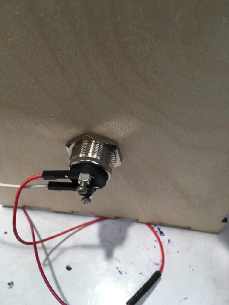
Mounting button to front of box
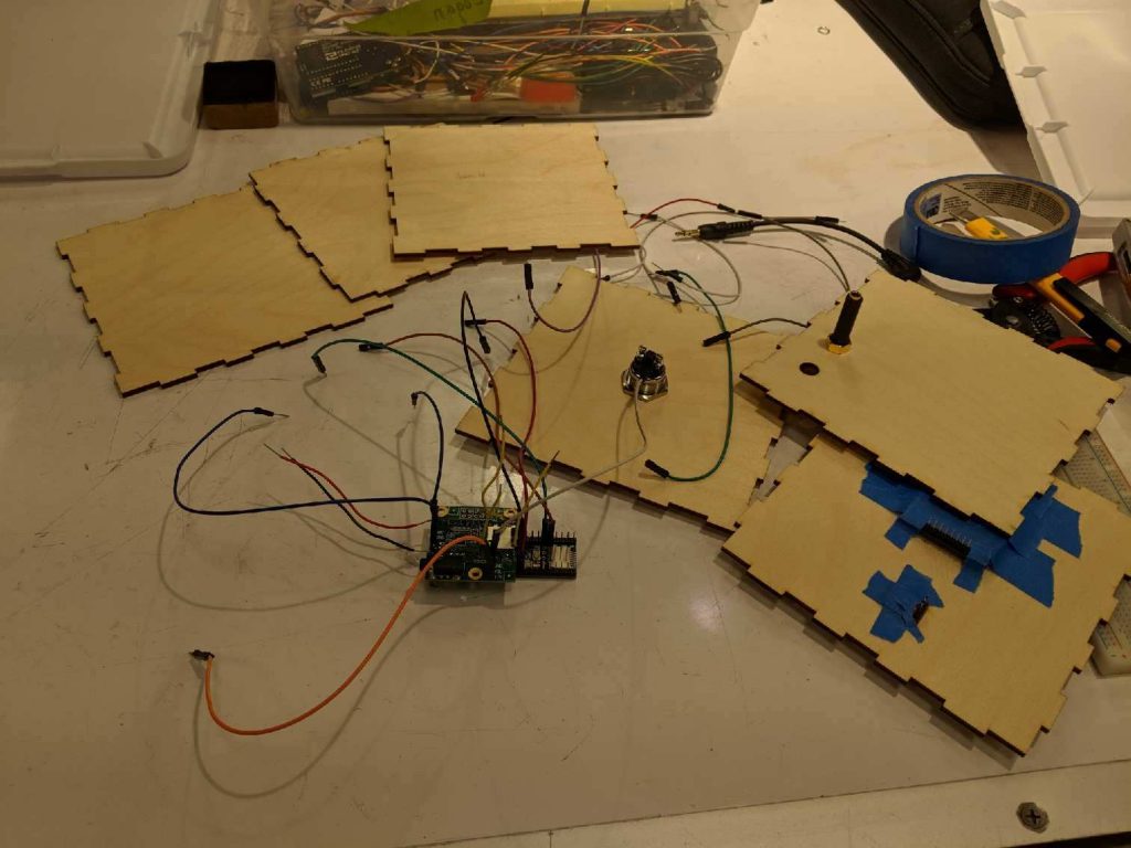
After mounting everything, we needed to check again that everything worked and then put our box together. First, we taped the microphone and RFID tag reader to the top of the box. Next, we taped the Teensy to the button of the box and started rewiring everything and gluing the box together.
Testing everything while the jacks and button are mounted to the lasercut box
Putting the box together: taped RFID tag reader and mic to top of box
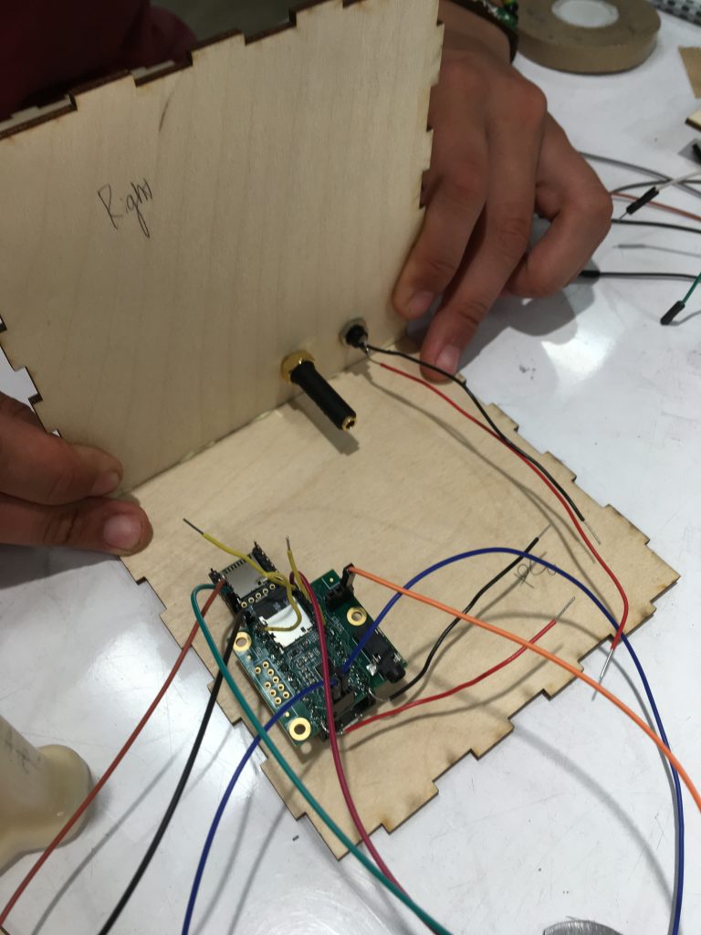
Putting the box together. First, connected the bottom and right side together.
Overall, we followed our initial design for our final project although we didn’t quite follow our design plan since we ran into a lot more difficulties than expected, so we finished a lot later than expected (1 am the night before it was due).
Conclusions and lessons learned:
Much of the feedback we received was positive, which was really nice to hear. Joseph and his wife were especially happy with our project. The two standout constructive criticisms were that the audio quality was a large barrier to practical use, and that some aspects of the physical design could be improved to make interacting with it more intuitive. The design feedback mainly revolved around the device being too minimal and not enough visual queues for things like if the box registered a tap, or how to know where the microphone is. Improving the way we record/playback audio would be the biggest thing I’d improve before bringing this project to any kind of product scale. Another huge critique we received was on the design of the box. A few people would have preferred it to be smaller and Joseph himself requested if we could make it look more like a book, which if given more time would be one quick thing to fix.
A large part of working with an older person as a client was realizing that we really didn’t have to change much of the design process to make something useful. As much as some people might have different problems from each other, learning to work and design things to solve problems is a universal skill. One big surprise for us was how tech savvy Joseph was. We really didn’t need to explain much for him to get our ideas or the purpose of the project, which was great and a huge plus when planning the design. I was also surprised by how easy it was to talk to and work with Joseph since I was initially nervous due to the huge age gap.
A big takeaway from this course has been simple things take a lot of work to get right. This project is a great example of that because it has a very simple (in our opinion) interaction, but it took a lot of testing and tweaking to get it working nicely. Some challenges from the software side were mainly getting the hardware modules to work nicely with each other. Translating the RFID tags to strings to store the audio files was more challenging that we initially thought. Specifically translating the byte representation to a string took a while to debug because of some quarks of how the Arduino deals with strings/char arrays. Also making the SD writer and audio shield play nicely with the RFID reader was an additional source of challenge as they communicate over I2C so we had to switch around a few default pins so they’d all end up on the same bus.
Technical details:
Better formatted code here
/******************************************************************************************
* *
* Intro to Physical Computing: Final Project *
* Bookmark Box *
* *
* Logan Kojiro -- Kristie Lord *
* ****************************************************************************************
* Parts of this are modified from a MFRC522 library example; see *
* https://github.com/miguelbalboa/rfid for further details and other examples. *
* *
* Audio Recording is modified from example code with the teensy audio library *
* See Examples->Audio->Recorder *
* *
* Released into the public domain. *
* ****************************************************************************************
*/
/************ LIBRARIES ************/
#include <SPI.h>
#include <MFRC522.h>
#include <SD.h>
#include <Audio.h>
#include <SerialFlash.h>
#include <Bounce.h>
/************ SETUP FOR RECORDING ************/
AudioInputI2S i2s2;
AudioAnalyzePeak peak1;
AudioRecordQueue queue1;
AudioPlaySdRaw playRaw1;
AudioOutputI2S i2s1;
AudioConnection patchCord1(i2s2, 0, queue1, 0);
AudioConnection patchCord2(i2s2, 0, peak1, 0);
AudioConnection patchCord3(playRaw1, 0, i2s1, 0);
AudioConnection patchCord4(playRaw1, 0, i2s1, 1);
AudioControlSGTL5000 sgtl5000_1;
/************ GLOBALS & PIN ASSIGNMENTS ************/
#define RST_PIN 37
#define SS_PIN 38
#define SDCARD_CS_PIN 10
#define SDCARD_MOSI_PIN 7
#define SDCARD_SCK_PIN 14
const int myInput = AUDIO_INPUT_MIC;
const int BUTTON = 32;
File frec; //file where data is recorded
MFRC522 mfrc522(SS_PIN, RST_PIN); // Create MFRC522 instance.
Bounce buttonRecord = Bounce(BUTTON, 8);
char *curr_tag = NULL;
bool recording = false;
/******************************************************************************************
* Setup: *
* ****************************************************************************************
*/
void setup() {
pinMode(BUTTON, INPUT_PULLUP);
AudioMemory(60);
sgtl5000_1.enable();
sgtl5000_1.inputSelect(myInput);
sgtl5000_1.volume(0.5);
Serial.begin(9600);
SPI.setMOSI(SDCARD_MOSI_PIN);
SPI.setSCK(SDCARD_SCK_PIN);
SPI.begin();
Serial.println("Initializing Card...");
mfrc522.PCD_Init(); // Init MFRC522 card
mfrc522.PCD_DumpVersionToSerial(); //show details of card reader module
Serial.println("Done.");
Serial.println("Initializing SD Card...");
if (!(SD.begin(SDCARD_CS_PIN))) {
// stop here if no SD card, but print a message
while (1) {
Serial.println("Unable to access the SD card");
delay(1000);
}
}
Serial.println("Done.");
Serial.println("\n\n--Begin Main--\n\n");
}
/******************************************************************************************
* Main Loop: *
* ****************************************************************************************
*/
void loop() {
buttonRecord.update();
if (buttonRecord.fallingEdge()) {
Serial.println(curr_tag);
record();
}
else {
if (mfrc522.PICC_IsNewCardPresent()) {
free(curr_tag);
Serial.println("Found Card!");
//make sure we can read the card
if ( !mfrc522.PICC_ReadCardSerial()) return;
//construct the filename from the card's UID
String file = "";
for (byte i = 0; i < mfrc522.uid.size - 1; i++) {
file += String(mfrc522.uid.uidByte[i]);
}
file += ".RAW";
//some arguments for SD functions must be of type (char *)
//not String so we must convert the String to a Char*
char *buf = (char*)malloc(sizeof(char) * (file.length() + 1));
file.toCharArray(buf, file.length() + 1);
curr_tag = buf;
Serial.print("Tag Filename: ");
Serial.println(curr_tag);
play_msg(curr_tag);
}
mfrc522.PICC_HaltA();
}
}
/******************************************************************************************
* record: while button is held, record from mic *
* and write to SD card *
* ****************************************************************************************
*/
void record() {
if (curr_tag == NULL) {
Serial.println("ERROR: No Card has been tapped");
return;
}
Serial.print("Recording to file ");
Serial.print(curr_tag);
Serial.println("...");
startRecording(curr_tag);
if (!recording) {
Serial.println("ERROR: Unable to write to SD card");
return;
}
while (!digitalRead(BUTTON)) {
continueRecording();
}
stopRecording(curr_tag);
}
/******************************************************************************************
* play_msg: open sound file from SD card and playback *
* *
* ****************************************************************************************
*/
void play_msg(char *filename) {
Serial.print("Playing Message from file ");
Serial.print(filename);
Serial.println("...");
if (!SD.exists(filename)) {
Serial.println("No recording for this tag yet");
return;
}
playRaw1.play(filename);
while (playRaw1.isPlaying()) {
}
playRaw1.stop();
Serial.println("\nDone.");
}
/******************************************************************************************
* startRecording: open SD file and begin the recording queue *
* *
* ****************************************************************************************
*/
void startRecording(char *filename) {
Serial.println("Recording...");
if (SD.exists(filename)) {
// The SD library writes new data to the end of the
// file, so to start a new recording, the old file
// must be deleted before new data is written.
SD.remove(filename);
}
frec = SD.open(filename, FILE_WRITE);
Serial.println(filename);
if (frec) {
queue1.begin();
recording = true;
}
}
/******************************************************************************************
* continueRecording: Fetch 2 blocks from the audio library and copy *
* into a 512 byte buffer. The Arduino SD library is most efficient *
* when full 512 byte sector size writes are used. *
* ****************************************************************************************
*/
void continueRecording() {
if (queue1.available() >= 2) {
byte buffer[512];
memcpy(buffer, queue1.readBuffer(), 256);
queue1.freeBuffer();
memcpy(buffer + 256, queue1.readBuffer(), 256);
queue1.freeBuffer();
// write all 512 bytes to the SD card
frec.write(buffer, 512);
}
}
/******************************************************************************************
* stopRecording: stop recording to the queue, save additional data left *
* on the queue, and close the SD file *
* *
* ****************************************************************************************
*/
void stopRecording(char *filename) {
queue1.end();
if (recording) {
//write the rest of the audio buffer to the file and close it
while (queue1.available() > 0) {
frec.write((byte*)queue1.readBuffer(), 256);
queue1.freeBuffer();
}
frec.close();
}
recording = false;
Serial.print("\nRecorded to ");
Serial.println(filename);
}
[\code]
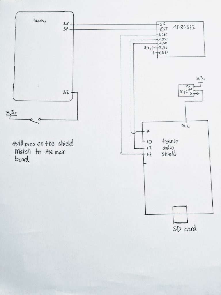
Schematic
Website used to make box: http://www.makercase.com/
DXF file of box:
Leave a Reply
You must be logged in to post a comment.