
Team Members: Ryan, Willow, Chileshe
INTRODUCTION
The purpose of this project was to create an assistive device for Phil Sidel, an elderly individual in our community. Phil lives a very simple life that consists of waking up to read emails in the morning, walking to the Jewish Community Center to shower and have lunch, come back home to edit monthly newsletters for the Explorers Club, make peanut butter jelly sandwiches or soup for dinner, and then solve sudoku puzzles until it is time to sleep. Since his day-to-day schedule consists of basic tasks that he doesn’t need much help in completing, we thought the best product to make for him would be a puzzle because its what he loves to do in his free time. Chileshe came up with the initial idea of having three hidden operations and having the user input the four numbers in order to reach a final goal number. Phil loved the idea of this and took time in analyzing how he would solve a problem like this, so we decided to go along with his idea into its final form. We’ve described below the process we took to create this box.
To see our documentation for our initial meeting: https://courses.ideate.cmu.edu/60-223/s2018/work/meeting-documentation/
To see our documentation for our initial prototype: https://courses.ideate.cmu.edu/60-223/s2018/work/team-red-chameleon-prototype-documentation/
WHAT WE BUILT
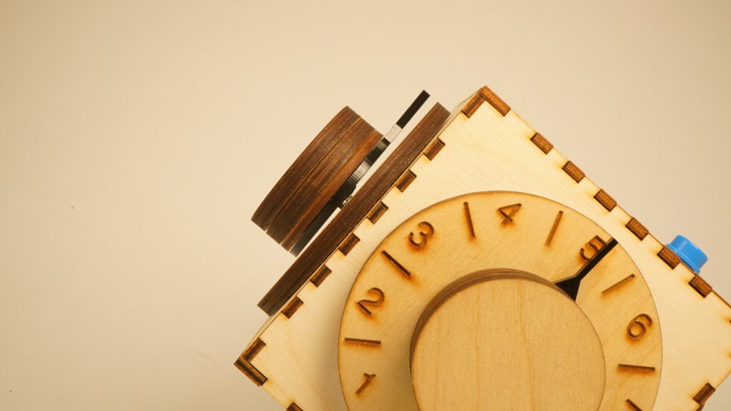
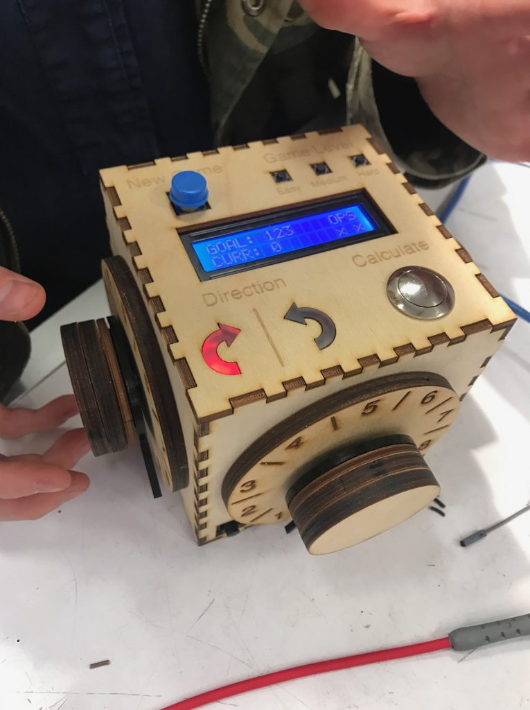
The puzzle box has four dials, one on each of its sides, where each dial represents a number from 1-9 and can be controlled by the user. There are three operations (addition, subtraction, or multiplication) that occurs between each of the numbers. The mathematical result from the four numbers that are chosen by the user through the dials and the three hidden operations chosen by the Arduino is shown through the display on the top of the box as “Curr” for Current Number. It also displays a “Goal” which is the number that the user is trying to reach through changing the four numbers. If the user successfully reaches the goal number, then it displays “You’ve Won!” on the display and gives you a new puzzle. This puzzle box was inspired by Phil’s passions for puzzles, specifically the KenKen puzzle, which consists of giving operations and the user having to fill in the numbers in order to reach a desired number. This puzzle box is the complete reverse where we choose the operations and the user has to decide on the numbers, so we thought it would be new and creative for Phil to be able to solve a different type of math puzzle.
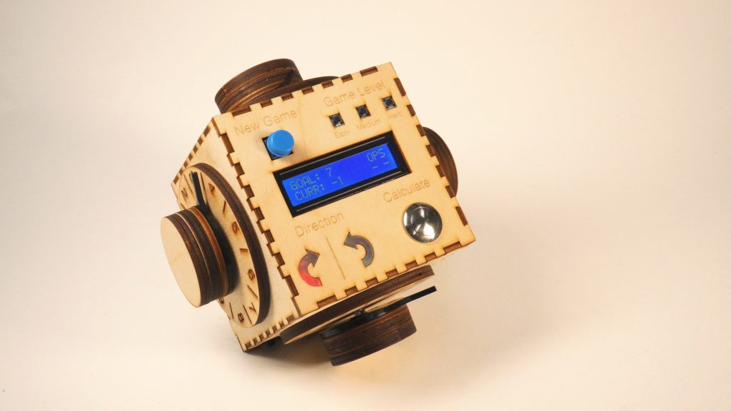
Overall View of the Puzzle Box
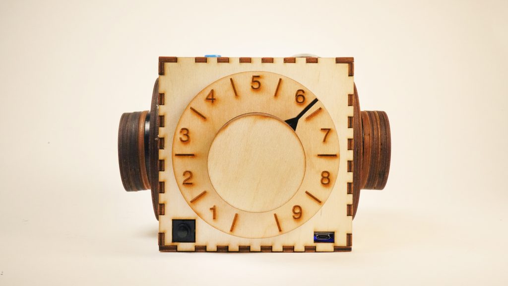
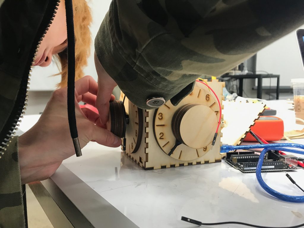
Front View – Details of the Number Knob, On/off Switch and Charging Port
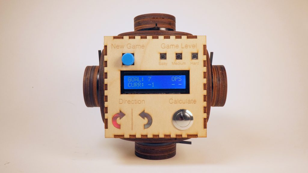
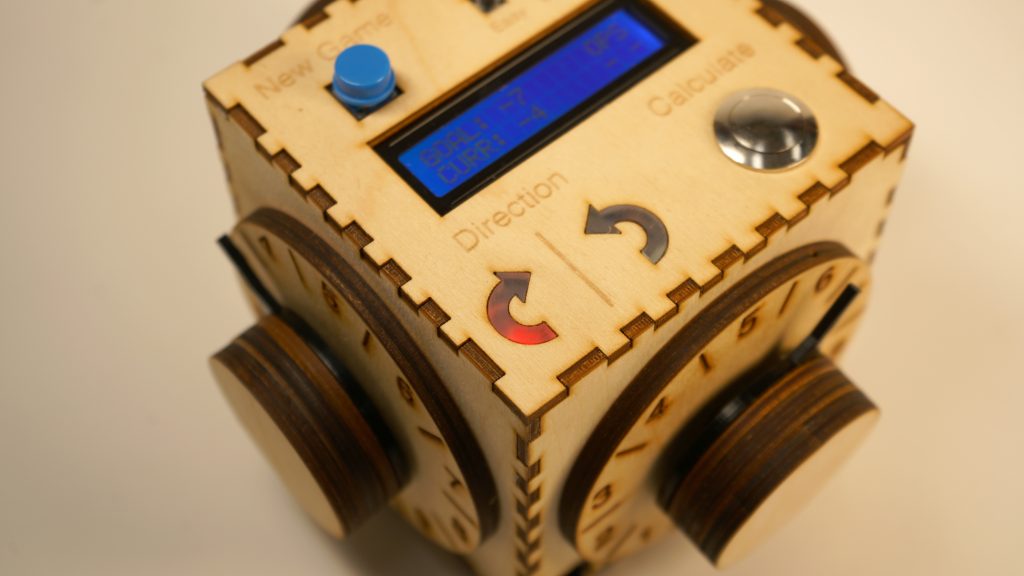
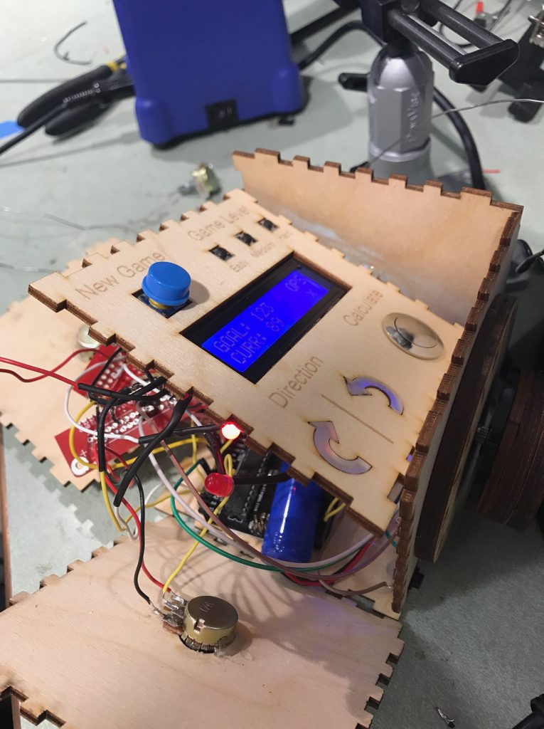
Top View – Details of the Game Controls and Displays
Craft Details – Sanded Acrylic Panels Softening LED Lights
Craft Details – Floating Number Knobs Ensuring Smoothness
HOW WE GOT HERE
Our puzzle box for the prototype was fully functional, so the process in making the final product of the box was not very different, with just some improvements. We’ve improved it by having solder connections instead of having loose female-male wire and breadboard connections. We’ve also improved the number knob to display the numbers more clearly and by also showing the range for each of the numbers. Although these improve seem simple and small, these changes caused many issues with the hardware as explained in further details below.
- Using Solder Connections
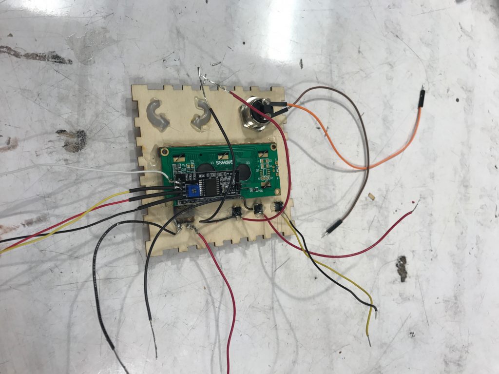
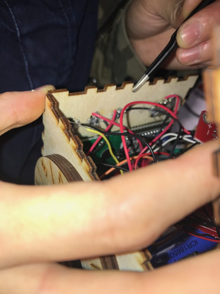
A big improvement we made with this project from the prototype was by soldering all of our connections that are inside of the board so that no wires can come loose. Instead of using breadboards, we used the thin breadboards, where we can solder in the connections directly into the thin breadboard, for all connections to 5V and Ground.
The solder connections for the top face.
Breaking thin breadboards into smaller sizes to fit inside of the box.
A look into the box for how the thin breadboard/solder connections for the potentiometer all come together.
- Number Knob Improvement
Based on feedback from Philip, we improved the design of the number knobs on four sides of the puzzle box. We scaled up the numbers so that Philip can read the input more easily. We also added the range lines, and made the number hand pointing to a number range instead of a specific number, this way Philip doesn’t need to make the number hand perfectly align with the actual number display when he wants to choose that number. In addition, we doubled the thickness of the number hand, so that it doesn’t easily break.
Installing the knobs with the improved dials
- Rechargeable Battery
The rechargeable battery was a new hardware for all of us, so it was difficult to figure out how to use at first. However, it was definitely a huge improvement from the first prototype because the prototype ran off a 9V battery and would have to be replaced by opening up the box, which would’ve been impossible to do with all of the wiring. Also a power cable would’ve been difficult to use because you need to rotate the box as you’re using it, so a power cable would’ve inhibited the user’s movements. Therefore, the rechargeable battery allows the user to interact with the box without being limited by a cable while also being able to charge it through a cable while not using it.
- Assembling using Super Glue
The prototype of the puzzle box was glued together using hot glue, which was thought was sufficient to keep the box together. However, we found that with some pressure, each of the faces could come out, so we used super glue to assemble the knobs and the box together. Therefore, the box would be more durable and would not break as easily.
Assembling the box using super glue.
- Potentiometer Malfunctioning
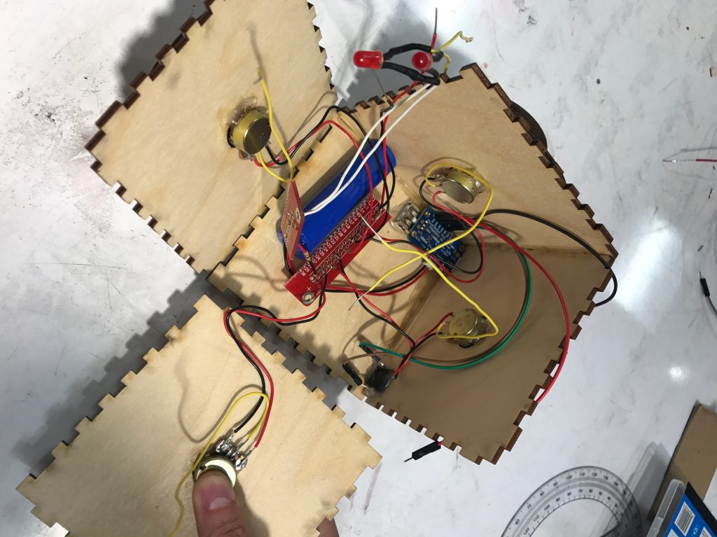
The biggest problem we encountered during the assembly process was with the potentiometers. After wiring and gluing all potentiometers in place, we found that they are not working properly: the numbers are jumping all over the place. We checked every single place that could go wrong, and changed the four potentiometers for so many times, however the problem still persisted. Then we noticed that if we press the legs of the potentiometers, sometimes they would turn back to their normal state. We realized that the problem might come from the connection area. We decided to calm down and thought hard about any differences between our final model and our previous perfectly functioning prototype. We eventually figured out: the wires were soldered into the holes above the potentiometer legs instead of the legs themselves, and that somehow damaged the potentiometers. This was a big lesson for us: we should’ve done testing for smaller parts before assembly everything together.
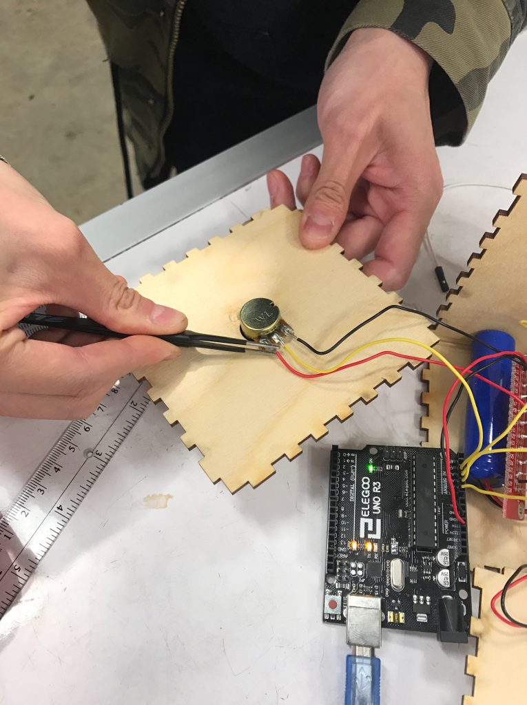
Trying to debug the potentiometer issue with the solder
- LCD Display Dimming Problem
During the assembly process, our LCD display was somehow really dim. Initially we thought this was a wiring problem, but we did not find anything wrong after careful checking. We then used the voltage meter and found out that the LCD was not receiving enough power. Later we found that the problem comes from the change of the power source. The LCD needs to be directly powered from the re-chargable battery instead of from the Arduino board like what we had before.
Fixing the dim LCD problem before final assembly.
- Level Button Connection Mistake
After we assemble all three level buttons in place, they are not working. We checked the wiring and found that one of the buttons was soldered on the wrong side of the legs. Again, we probably should’ve test the button one by one before gluing everything into the wood.
Despite all of these issues, we were able to complete the fully functional puzzle box after 15 hours of work put into the physical creation of it. Most of the time went into fixing the potentiometers not working when soldered, but it was well worth the effort in the end. Phil loved it and we can not wait to hear responses on his experiences with it.
Final testing of the box after assembly.
CONCLUSIONS & LESSONS
In our final critique, we received positive feedback for the most part and varying responses on whether the puzzle was solvable for them or just impossible for them to solve. Individuals seemed to enjoy playing with our device and thought it was an intriguing idea to make a project like ours. They suspected that an algorithm may be achieved to solve the puzzle more easily, but this did not take away from enjoyment of interacting with the device. We generally received positive feedback. One individual suggested a set of instructions to go along with the device, although we did not think this was necessary because this box was meant for Phil and the instructions would be explained to him in person. Something we learned through the critique was that Phil had misunderstood our initial explanation of the box, making it seem like the puzzle was awfully harder than it actually was. However, Phil was able to understand the puzzle fully through this critique and found the puzzle to be definitely solvable, which was good feedback to hear.
We’ve learned a few things in this project, with communication as one of the most significant areas. Communication of ideas must be done very patiently, and with a lot of tact. We noticed that there was often a misunderstanding when we explained the working of the device to the elderly. What seemed intuitive to us, was easily misinterpreted by others despite its seeming simplicity. For instance, there’s a number representing current value of the operations on the device, along with the symbol “CURR” indicating this, but a few individuals needed more explanation to understand that this was the case. We experienced a similar issue, once or twice, with the number labeled as the “GOAL”. Intuitions differ between individuals, and people often jump to different assumptions, even for simple mechanisms. Since this was inspired by the KenKen puzzle, one that Phil loves to solve, Phil kept thinking that the rules of KenKen were what we were trying to go for and kept asking us what the operations were. However, after he understood that the operations was what was hidden and was supposed to be solved for, he started to understand the puzzle much better from there.
A very significant lesson, as mentioned earlier, is the value of testing. We experienced several unexpected issues relating to soldering or potentiometers in our project, which stopped our final device construction for many hours. Testing every single piece after any sort of change, no matter how minor, can save a lot of time. We focused on testing the initial wiring of the device, so that we could write code for it. However, we should have continued testing each piece throughout the final construction process. We were extremely confident after the prototyping phase, so we did not consider that issues might emerge in our final design, especially because the changes we made after prototyping were extremely minor. Ironically, the time we assumed would be wasted on extra testing, would have saved us several times that duration on constructing the final device.
TECHNICAL DETAILS
-
-
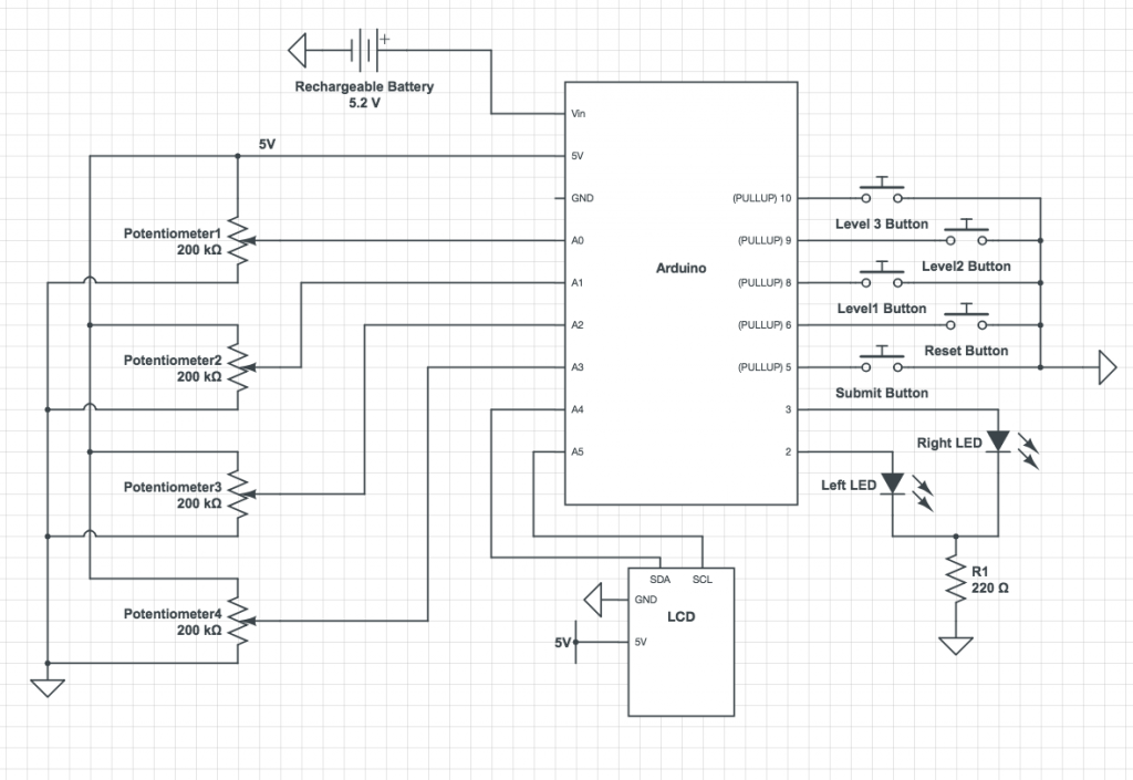
- Schematic
-
-
-
- Code
-
#include <LiquidCrystal_I2C.h>
#include <Wire.h>

//I2C pins declaration
LiquidCrystal_I2C lcd(0x27, 2, 1, 0, 4, 5, 6, 7, 3, POSITIVE);

//The Pins being used for this project
int pot1Pin = A0;
int pot2Pin = A1;
int pot3Pin = A2;
int pot4Pin = A3;
int ledPinLeft = 2;
int ledPinRight = 3;
int submitPin = 5;
int resetPin = 6;
int level1Pin = 8;
int level2Pin = 9;
int level3Pin = 10;

//initialize global variables
int level = 1;
int val1 = 0;
int val2 = 0;
int val3 = 0;
int val4 = 0;
int num1 = 0;
int num2 = 0;
int num3 = 0;
int num4 = 0;
int op1 = 0;
int op2 = 0;
int op3 = 0;
int sol = 0;
int direc = 0;
int start = 0;
int ans = 0;
int press_time = 0;
int last_time = 0;
int press_reset_time = 0;
int last_reset_time = 0;

void setup() {
  lcd.begin(16, 2); //Defining 16 columns and 2 rows of lcd display
  lcd.backlight(); //To Power ON the back light

  //Initialize the modes of each pin
  pinMode(pot1Pin, INPUT);
  pinMode(pot2Pin, INPUT);
  pinMode(pot3Pin, INPUT);
  pinMode(pot4Pin, INPUT);
  pinMode(ledPinLeft, OUTPUT);
  pinMode(ledPinRight, OUTPUT);
  //buttons are input_pullup
  pinMode(submitPin, INPUT_PULLUP);
  pinMode(resetPin, INPUT_PULLUP);
  pinMode(level1Pin, INPUT_PULLUP);
  pinMode(level2Pin, INPUT_PULLUP);
  pinMode(level3Pin, INPUT_PULLUP);

  randomSeed(analogRead(A5)); //for the random number generator

  //initialize first puzzle that will be given once started up
  direc = random(0, 2);
  start = random(0, 4);
  op1 = random(0, 3);
  op2 = random(0, 3);
  op3 = random(0, 3);
  num1 = random(1, 10);
  num2 = random(1, 10);
  num3 = random(1, 10);
  num4 = random(1, 10);
  sol = generateSolandDirec(num1, num2, num3, num4, op1, op2, op3);

  Serial.begin(9600);
}


int generateSolution(int num1, int num2, int num3, int num4, int op1, int op2, int op3) {
  /*This function takes in four numbers and the operations between them, and returns what
    the output number is. It follows order of operations */
  if (((op1 == 2) && (op2 == 2)) && (op3 == 2)) {
    return num1 * num2 * num3 * num4;
  }
  else if ((op1 == 2) && (op2 == 2)) {

    if (op3 == 1) {
      return num1 * num2 * num3 - num4;
    }
    return num1 * num2 * num3 + num4;
  }
  else if ((op2 == 2) && (op3 == 2)) {
    if (op1 == 1) {
      return num1 - num2 * num3 * num4;
    }
    return num1 + num2 * num3 * num4;
  }
  else if ((op1 == 2) && (op3 == 2)) {
    if (op2 == 1) {
      return num1 * num2 - num3 * num4;
    }
    return num1 * num2 + num3 * num4;
  }
  else if (op1 == 2) {
    if ((op2 == 0) && (op3 == 0)) {
      return num1 * num2 + num3 + num4;
    }
    else if ((op2 == 1) && (op3 == 0)) {
      return num1 * num2 - num3 + num4;
    }
    if ((op2 == 0) && (op3 == 1)) {
      return num1 * num2 + num3 - num4;
    }
    if ((op2 == 1) && (op3 == 1)) {
      return num1 * num2 - num3 - num3;
    }
  }
  else if (op2 == 2) {
    if ((op1 == 0) && (op3 == 0)) {
      return num1 + num2 * num3 + num4;
    }
    else if ((op1 == 1) && (op3 == 0)) {
      return num1 - num2 * num3 + num4;
    }
    if ((op1 == 0) && (op3 == 1)) {
      return num1 + num2 * num3 - num4;
    }
    if ((op1 == 1) && (op3 == 1)) {
      return num1 - num2 * num3 - num4;
    }
  }

  else if (op3 == 2) {
    if ((op1 == 0) && (op2 == 0)) {
      return num1 + num2 + num3 * num4;
    }
    else if ((op1 == 0) && (op2 == 1)) {
      return num1 + num2 - num3 * num4;
    }
    if ((op1 == 1) && (op2 == 0)) {
      return num1 - num2 + num3 * num4;
    }
    if ((op1 == 1) && (op2 == 1)) {
      return num1 - num2 - num3 * num4;
    }
  }


  if (((op1 == 0) && (op2 == 0)) && (op3 == 0)) {
    return num1 + num2 + num3 + num4;
  }
  else if (((op1 == 0) && (op2 == 0)) && (op3 == 1)) {
    return num1 + num2 + num3 - num4;
  }
  else if (((op1 == 0) && (op2 == 1)) && (op3 == 1)) {
    return num1 + num2 - num3 - num4;
  }
  else if (((op1 == 1) && (op2 == 1)) && (op3 == 1)) {
    return num1 - num2 - num3 - num4;
  }
  else if (((op1 == 1) && (op2 == 1)) && (op3 == 0)) {
    return num1 - num2 - num3 + num4;
  }
  else if (((op1 == 1) && (op2 == 0)) && (op3 == 0)) {
    return num1 - num2 + num3 + num4;
  }
  else if (((op1 == 1) && (op2 == 0)) && (op3 == 1)) {
    return num1 - num2 + num3 - num4;
  }
  else if (((op1 == 0) && (op2 == 1)) && (op3 == 0)) {
    return num1 + num2 - num3 + num4;
  }

}

int getValue(int val) {
  //given the value of the potentiometers, return what number the dial should be
  if (val < 19) {
    return 1;
  }
  else if (val < 160) {
    return 2;
  }
  else if (val < 300) {
    return 3;
  }
  else if (val < 460) {
    return 4;
  }
  else if (val < 590) {
    return 5;
  }
  else if (val < 720) {
    return 6;
  }
  else if (val < 855) {
    return 7;
  }
  else if (val < 1010) {
    return 8;
  }
  else {
    return 9;
  }
}


int generateSolandDirec(int num1, int num2, int num3, int num4, int op1, int op2, int op3) {
  //given the direction and starting point, call the generateSolution function with the desired order
  if (direc == 0) { //going right
    if (start == 0) {
      return generateSolution(num1, num2, num3, num4, op1, op2, op3);
    }
    else if (start == 1) {
      return generateSolution(num2, num3, num4, num1, op1, op2, op3);
    }
    else if (start == 2) {
      return generateSolution(num3, num4, num1, num2, op1, op2, op3);
    }
    else {
      return generateSolution(num4, num1, num2, num3, op1, op2, op3);
    }
  }
  else { // going left
    if (start == 0) {
      return generateSolution(num1, num4, num3, num2, op1, op2, op3);
    }
    else if (start == 1) {
      return generateSolution(num2, num1, num4, num3, op1, op2, op3);
    }
    else if (start == 2) {
      return generateSolution(num3, num2, num1, num4, op1, op2, op3);
    }
    else {
      return generateSolution(num4, num3, num2, num1, op1, op2, op3);
    }
  }
}

void loop() {

  //turn the direction LED's on according to the direction the puzzle is going
  if (direc == 0) {
    digitalWrite(ledPinLeft, HIGH);
    digitalWrite(ledPinRight, LOW);
  }
  else {
    digitalWrite(ledPinLeft, LOW);
    digitalWrite(ledPinRight, HIGH);
  }

  //read the values from the potentiometer
  int pot1Read = analogRead(pot1Pin);
  int pot2Read = analogRead(pot2Pin);
  int pot3Read = analogRead(pot3Pin);
  int pot4Read = analogRead(pot4Pin);

  //determine what level is pressed (initially at 1 if no button is pressed)
  int level1Read = digitalRead(level1Pin);
  int level2Read = digitalRead(level2Pin);
  int level3Read = digitalRead(level3Pin);
  if (!level1Read or !level2Read or !level3Read) {
    if (!level1Read) {
      Serial.print("Easy");
      level = 1;
    }
    else if (!level2Read) {
      Serial.print("Medium");
      level = 2;
    }
    else {
      Serial.print("Hard");
      level = 3;
    }
  }

  //check if the submit or new game buttons are pressed
  int submit = digitalRead(submitPin);
  int reset = digitalRead(resetPin);
  if (!submit) { //if the submit button is pressed
    press_time = millis();
    if (press_time - last_time >= 3000) { //if 3 seconds have passed since last press
      Serial.print("Submit");

      //get the value from each dial
      int val1 = getValue(pot1Read);
      int val2 = getValue(pot2Read);
      int val3 = getValue(pot3Read);
      int val4 = getValue(pot4Read);
      Serial.print(val1);
      Serial.print(val2);
      Serial.print(val3);
      Serial.print(val4);
      Serial.print("\n");

      //calculate what the current number is at
      ans = generateSolandDirec(val1, val2, val3, val4, op1, op2, op3);
      if (ans == sol) { //check if the guessed answer is equal to the goal
        //display "You've Won!" if the answer is correct
        lcd.setCursor(0, 0);
        lcd.print("YOU'VE WON!");
        delay(5000);

        //generate a new puzzle
        op1 = random(0, 3);
        op2 = random(0, 3);
        op3 = random(0, 3);
        num1 = random(1, 10);
        num2 = random(1, 10);
        num3 = random(1, 10);
        num4 = random(1, 10);
        direc = random(0, 2);
        start = random(0, 3);
        sol = generateSolandDirec(num1, num2, num3, num4, op1, op2, op3);
      }
      last_time = press_time;
    }
  }

  if (!reset) { //if reset button is pressed
    press_reset_time = millis();
    if (press_reset_time - last_reset_time >= 1000) { //ensure button has not been pressed twice within a second
      Serial.print("Reset");

      //generate a new puzzle
      op1 = random(0, 3);
      op2 = random(0, 3);
      op3 = random(0, 3);
      num1 = random(1, 10);
      num2 = random(1, 10);
      num3 = random(1, 10);
      num4 = random(1, 10);
      direc = random(0, 2);
      start = random(0, 3);
      sol = generateSolandDirec(num1, num2, num3, num4, op1, op2, op3);
      last_reset_time = press_reset_time;
    }
  }

  //display the goal number on the LCD
  lcd.setCursor(0, 0);
  lcd.print("GOAL: ");
  lcd.print(sol);

  //display the OPS on the LCD
  lcd.setCursor(13, 0);
  lcd.print("OPS");

  //display the current number on the LCD
  lcd.setCursor(0, 1);
  lcd.print("CURR: ");
  lcd.print(ans);

  if (level == 1) { //if easy level, display two operations
    lcd.setCursor(13,1);
    if (op1 == 0) {
      lcd.print("+");
    }
    else if (op1 == 1) {
      lcd.print("-");
    }
    else {
      lcd.print("x");
    }
    lcd.setCursor(15,1);
    if (op2 == 0) {
      lcd.print("+");
    }
    else if (op2 == 1) {
      lcd.print("-");
    }
    else {
      lcd.print("x");
    }
  }
  else if (level == 2) { //if medium level, display one operation
    lcd.setCursor(14,1);
    if (op1 == 0) {
      lcd.print("+");
    }
    else if (op1 == 1) {
      lcd.print("-");
    }
    else {
      lcd.print("x");
    }
  }
  delay(200);

  lcd.clear();//Clean the screen

  //if information is wanted about the values from potentiometer and the solution numbers uncomment these lines
//    Serial.print(getValue(pot1Read));
//    Serial.print(getValue(pot2Read));
//    Serial.print(getValue(pot3Read));
//    Serial.println(getValue(pot4Read));

//    Serial.print(val1);
//    Serial.print(val2);
//    Serial.print(val3);
//    Serial.print(val4);
//    Serial.print(" ");
//    Serial.print(num1);
//    Serial.print(num2);
//    Serial.print(num3);
//    Serial.print(num4);
//    Serial.print(" ");
//    Serial.print(op1);
//    Serial.print(op2);
//    Serial.print(op3);
//    Serial.print(" Direction: ");
//    Serial.print(direc);
//    Serial.print(" Start: ");
//    Serial.print(start);
//    Serial.print(" Answer: ");
//    Serial.print(ans);
//    Serial.print(" Solution: ");
//    Serial.println(sol);
}
-
-
- DXF file for the box design:
-
Leave a Reply
You must be logged in to post a comment.