by Karan Gugle and Lillie Widmayer

Description: Device that indicates how crooked or level a picture is by dimming/brightening an LED depending on how crooked the picture is and playing notes of varying pitch based on the brightness of the LED.
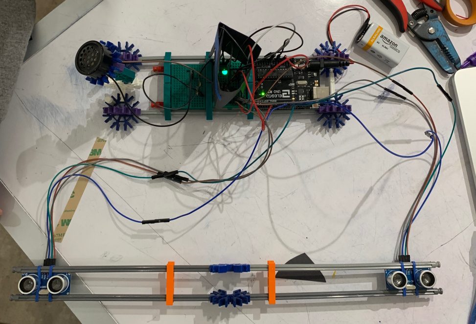
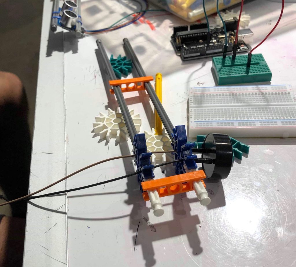
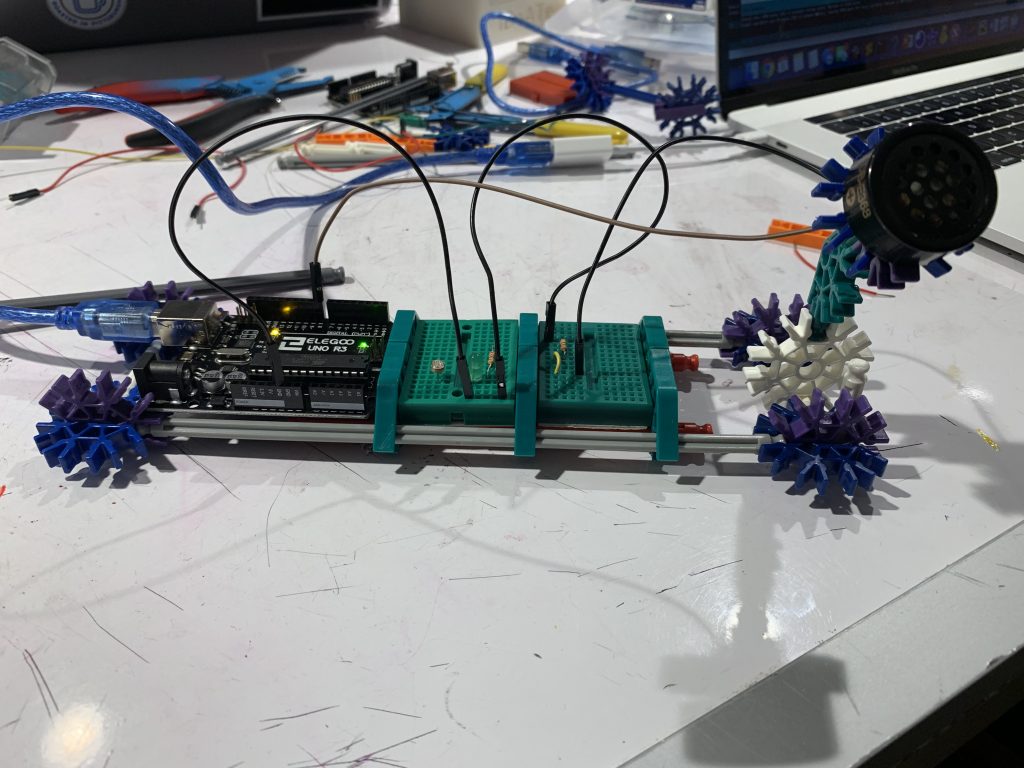
Progress Images:
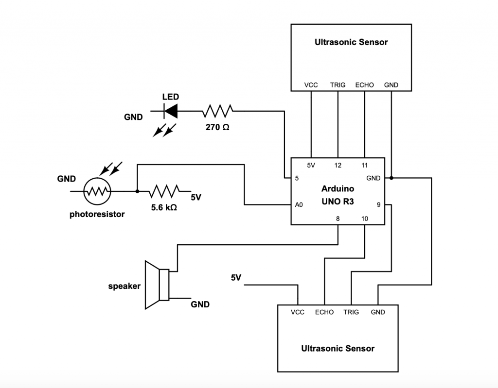
Schematic:
//Double Transducer: Picture Level
//This code reads data from the ultrasonic sensors and controls LED brightness and pitch of sound coming from the speaker.

#include <NewPing.h>
#include <toneAC.h>

//Ultrasonic sensors and photoresistor need to be connected to analog pins
//LED needs to be connected to a PWM pin to vary brightness
#define TRIG1  12
#define ECHO1     11
#define MAX1 200
#define TRIG2  13
#define ECHO2     10
#define MAX2 200

 NewPing sensors[2] = {     // Sensor object array
  NewPing(TRIG1, ECHO1, MAX1),
  NewPing(TRIG2, ECHO2, MAX2)
 };

 const int SPEAKER = 8;
 const int PHOTORESISTOR = A0;
 const int LED = 5;
 const float BASE = 33.65; //distance between two sensors

 void setup() {
  pinMode(PHOTORESISTOR, INPUT);
  pinMode(LED, OUTPUT);
  pinMode(SPEAKER, OUTPUT);
  Serial.begin(9600);
 }

 void loop() {
  int dist1;
  int dist2;
  delay(200);
  for (uint8_t i = 0; i < 2; i++) { // Loop through each sensor and read data.
    delay(50); //time delay in order to read data from both sensors
    if( i == 0) {
      dist1 = sensors[i].ping_cm();
    }
  else {
    dist2 = sensors[i].ping_cm();
  }
 }

 /*
 print statements for debugging:
     Serial.print("dist 1 = ");
     Serial.print(dist1);
     Serial.print(" dist2 = ");
     Serial.println(dist2);
 */

 int light = analogRead(PHOTORESISTOR);
   int diff = abs(dist1 - dist2);
   float angle = atan(diff/BASE)*(180/3.14); //angle calculated through trigonometry
   float brightness = log((angle + 9.0) / 90) * -15.0; //inverse relationship
   //between angle and brightness of LED

/*
More print statements for debugging:
     Serial.print("angle = ");
     Serial.println(angle);
     Serial.print("light = ");
     Serial.println(light);
 */

   analogWrite(LED, brightness);
   if(light > 380) toneAC(4500); //varying tone pitch based on LED brightness
   else if(light > 300) toneAC(3500);
   else if(light > 200) toneAC(2500);
   else toneAC(2000);
 }
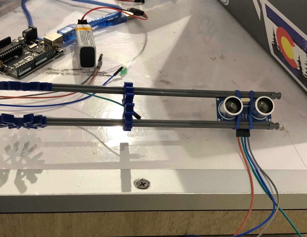
We encountered challenging situations while building the Picture Level and learned a lot in the process. One of the major difficulties we had was with the ultrasonic sensors, which measured the distance to the nearest object. Both of us had only worked with ultrasonic rangers through the class exercise, so it was easy for us to get a single sensor working. We wired up the second sensor the same way we had done for the first, but ended up only being able to read a single ranger’s output at any given time. We ended solving the problem by creating a sensor array and reading the output of both sensors sequentially and learned a few things about the NewPing library in the process.
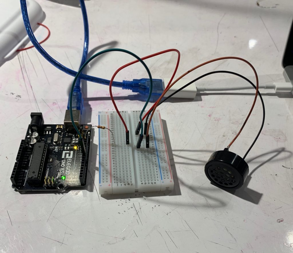
Another challenge we had was with the light and photoresistor relationship. We placed an LED directly adjacent to the photoresistor to capture how it dimmed and brightened according to the angle of the “painting”. However, the surrounding ambient light and the limited range of brightness the LED could produce led to a very small range of photoresistor values (300 – 350). This made it very hard for us to produce an accurate tone from the speaker, because we had such an inaccurate and limited range from the first transducer step. We decided to use the log() function to spread out the range of the photoresistor, so that it would be artificially more sensitive to changes in LED brightness.
Although these challenges were hard to overcome, we think it was smart to use sensors we had worked with before. Instead of fiddling around with the wiring / basics, we were able to concentrate on solving system-based challenges, which gave way to more thought and empirical testing. Our ultrasonic rangers encountered difficulties in accuracy due to the sequential reading of output and the delays we had set in the code, which is something we would adjust if we had to demo again.
Overall, we were able to create what we thought was an interesting project that required us to experiment and adjust as we worked. It brought together familiar sensors from class and applications of those sensors that were totally new to us. One aspect of the project both of us enjoyed was working with K’NEX to build housing for our breadboards, Arduino, and battery. Both of us see K’NEX as a good way to quickly prototype and hold together complex creations in the design phase. For the next project, we’d both like to focus more on brainstorming and planning. After seeing some of our other classmates creations, it would have beneficial if we could have created a more cohesive set of transducers.
Comments are closed.