
In order to improve Kathy’s life at home, we decided to create an automated light switch on a timer. Kathy explained to us that when she had guests over she would have to say goodbye downstairs, go up the stairs, watch them leave from an upstairs window, then go back downstairs to turn the porch light off. We wanted to help her streamline this process.
Previous Posts
What we built
The Light Switch 2.0 allows the user to time operation of the light switch such that it automatically turns off after a 10-minute delay, but also remains unobtrusive enough such that the user can still operate the light switch in an ordinary manner.
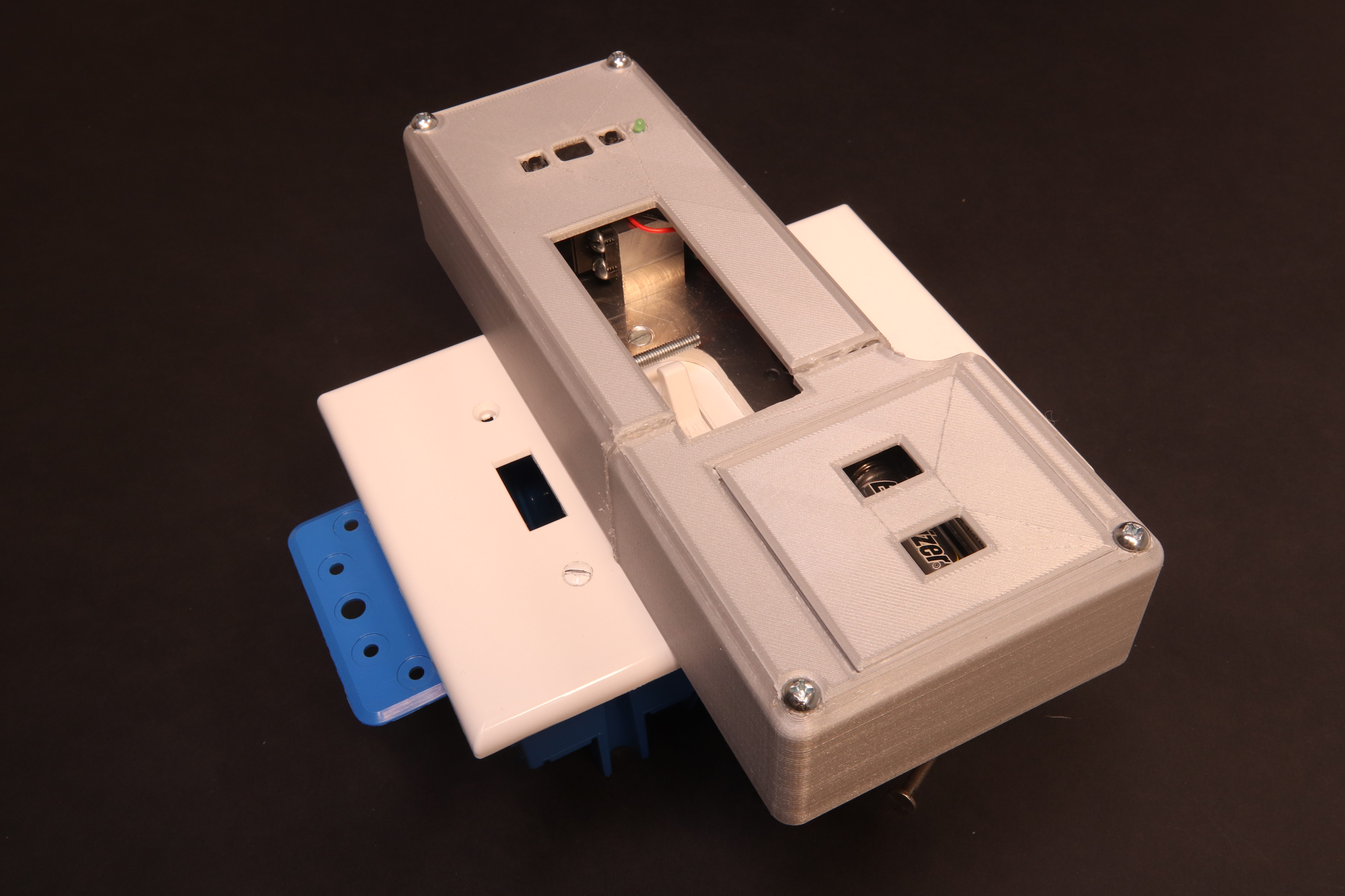
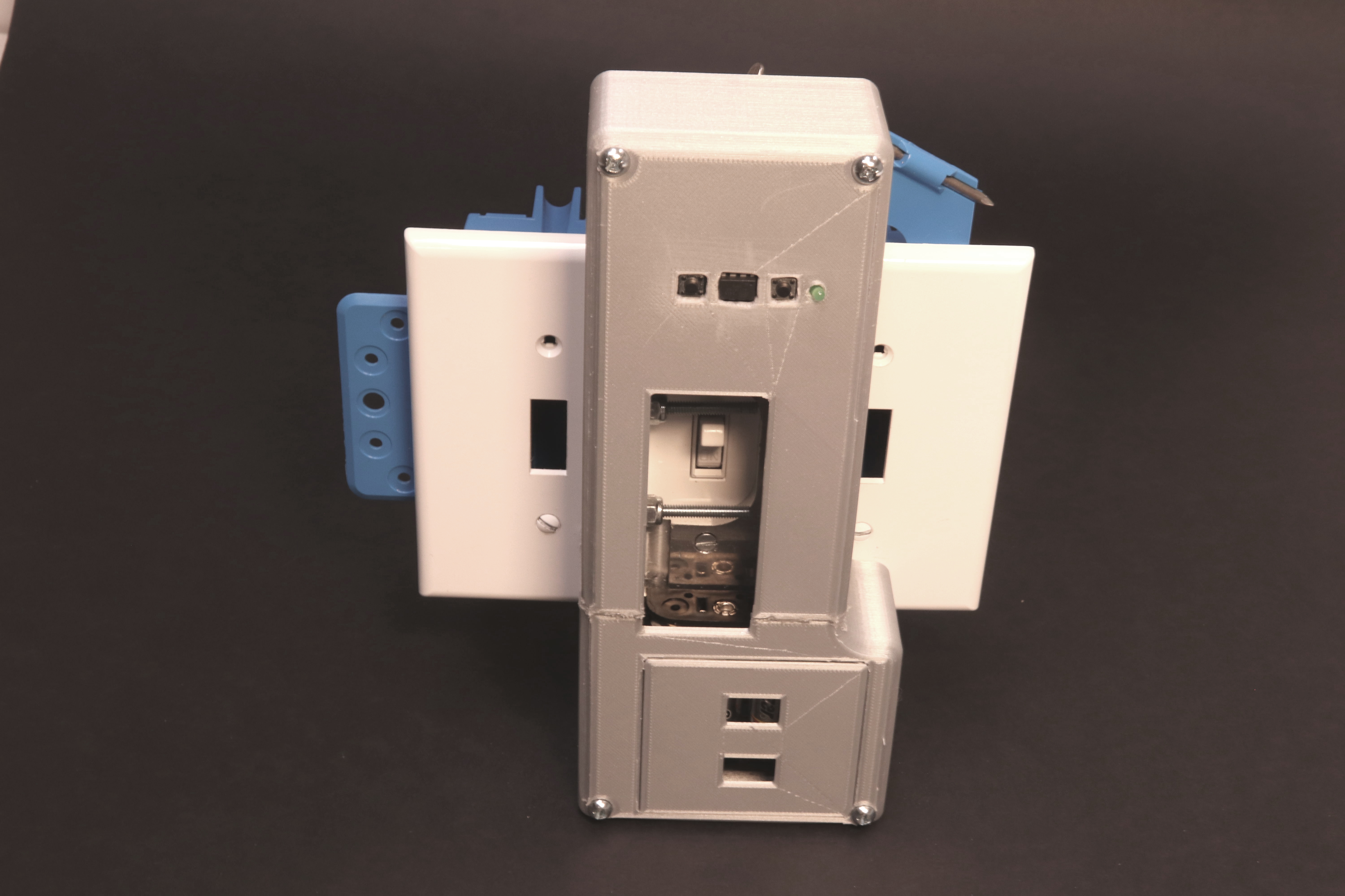
Overall photo showing the project.
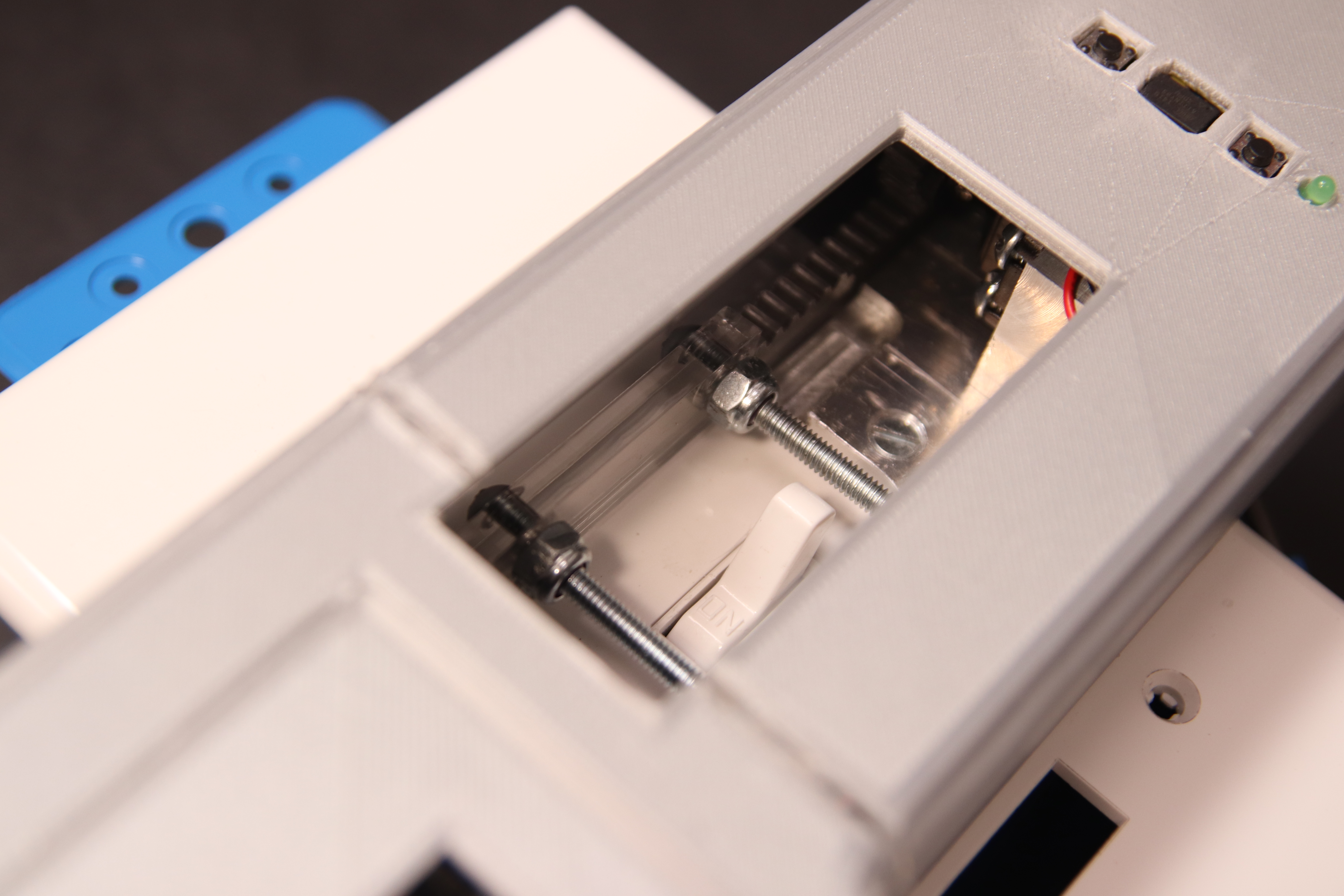
The switch mechanism does not obstruct usage of the switch, but some of it is visible.
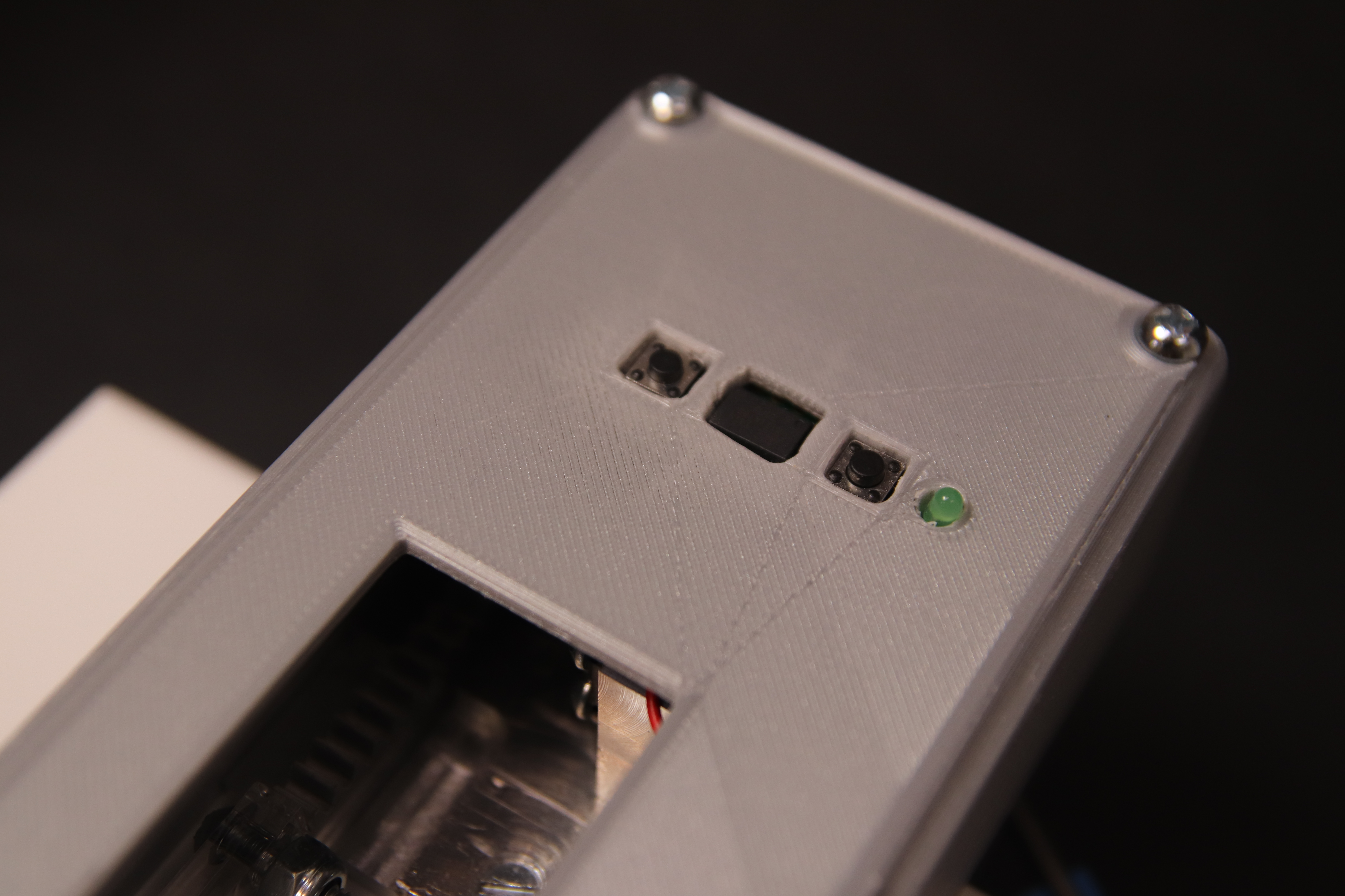
The control panel which houses the buttons and LED. The left button operates the switch instantly; the right button starts a timer process.
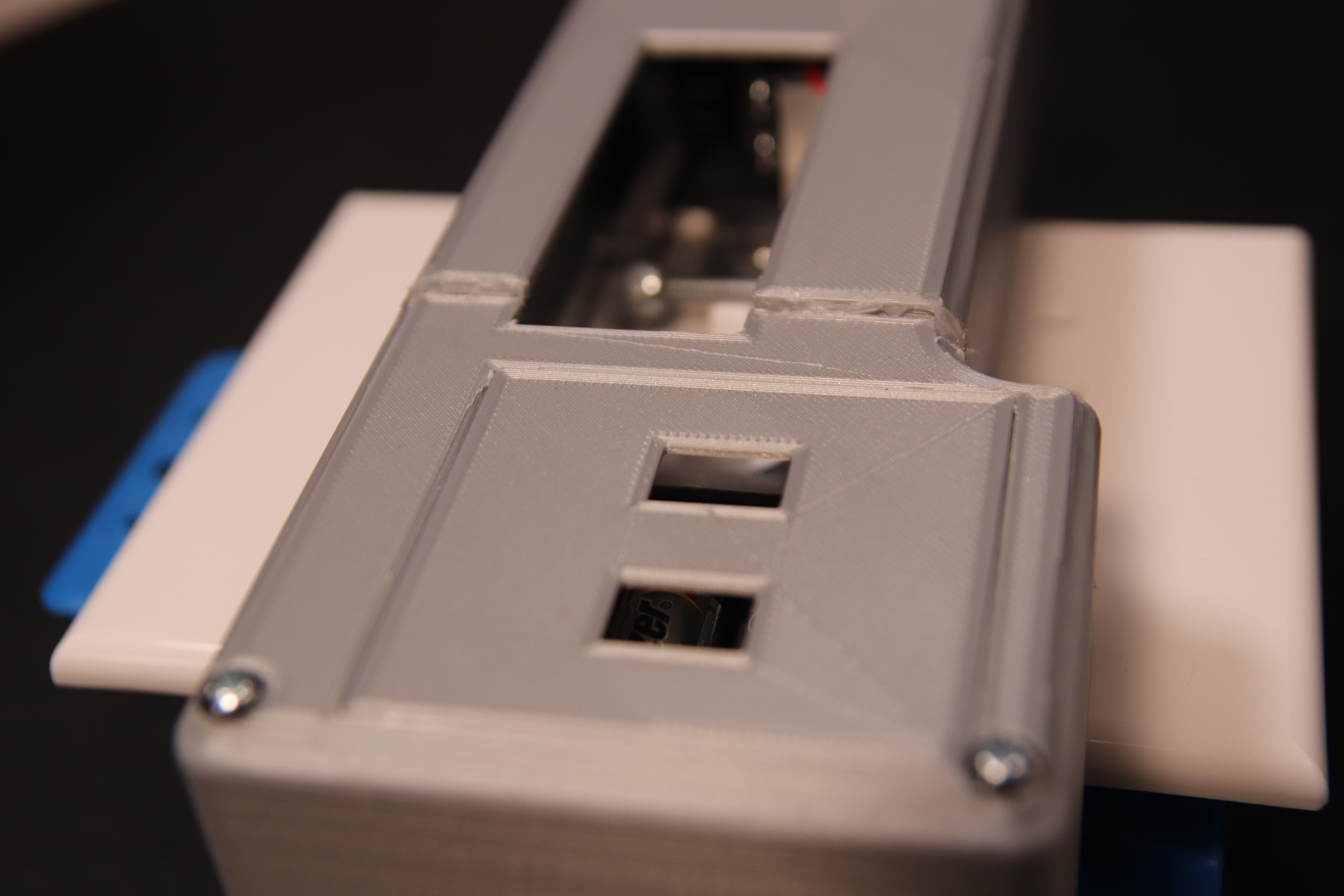
The panel lifts to expose the batteries for easy access.

When the timer button is pressed, the LED lights up to indicate as such.
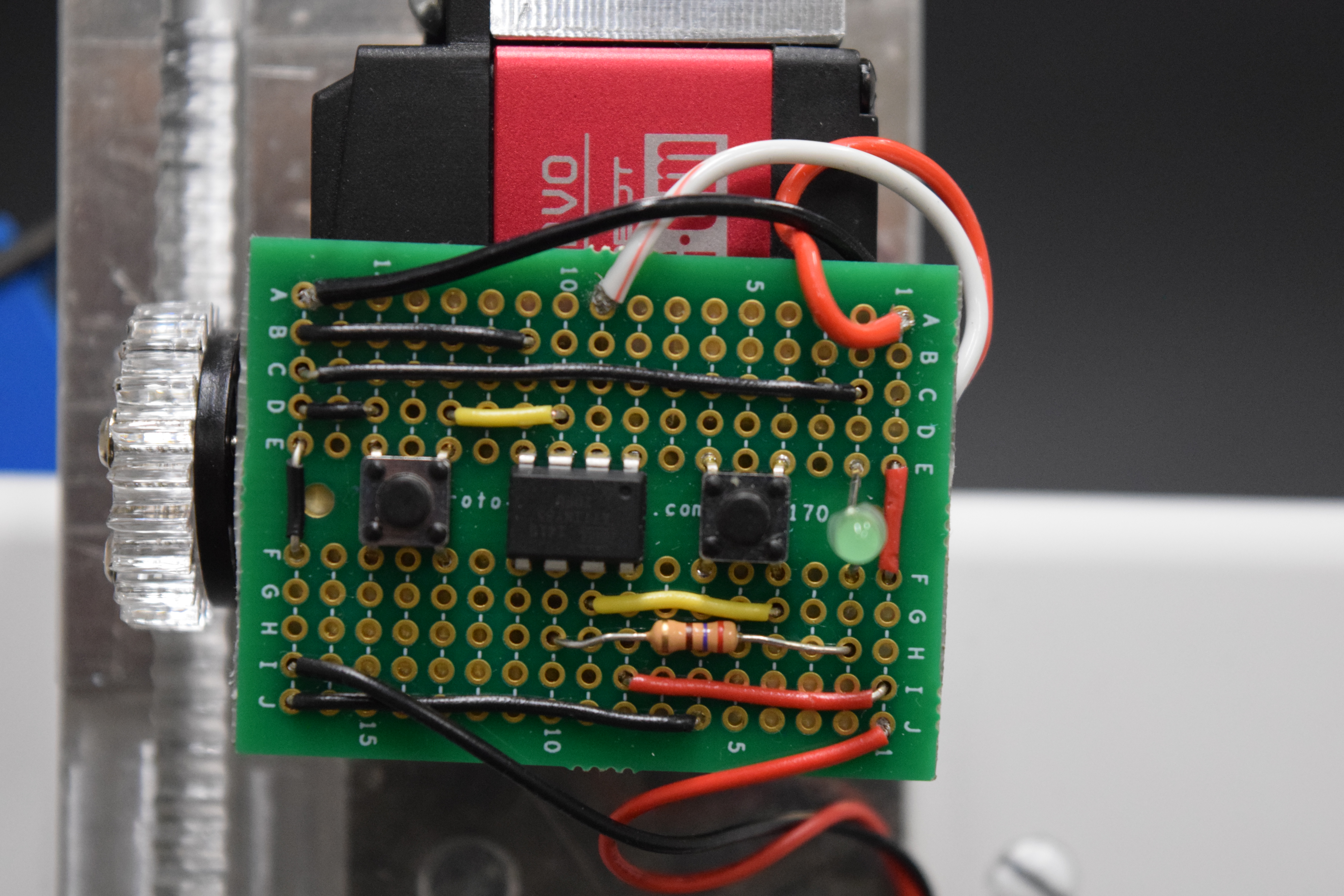
Close up of protoboard wiring.

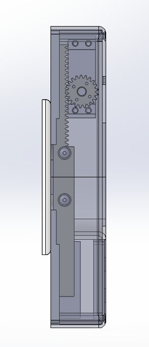
Close up of rack and pinion.
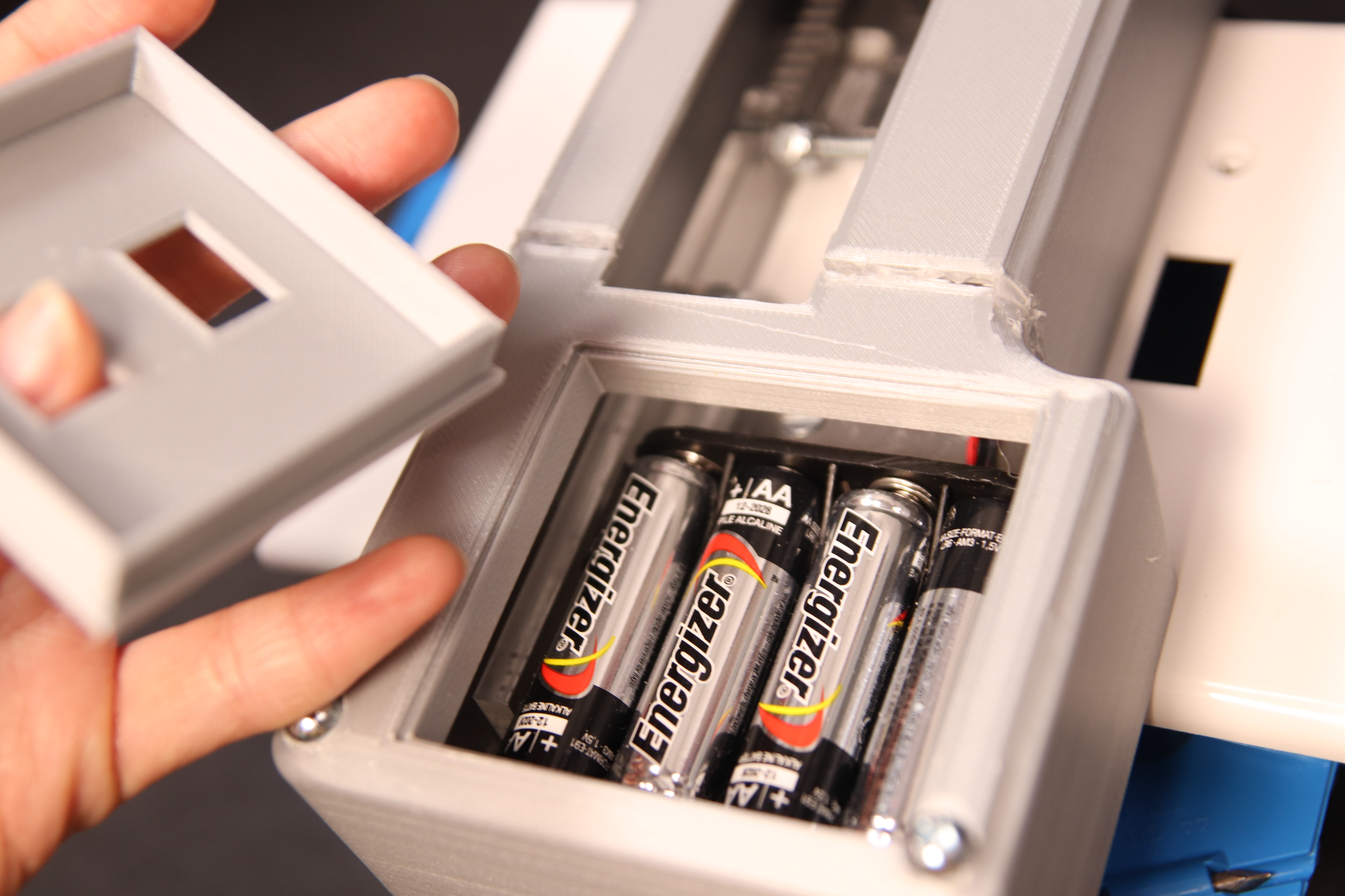
Looking at the battery panel. It uses a pack of four AA batteries and should run for a long, long time.

The switch is fully operable as a normal light switch.
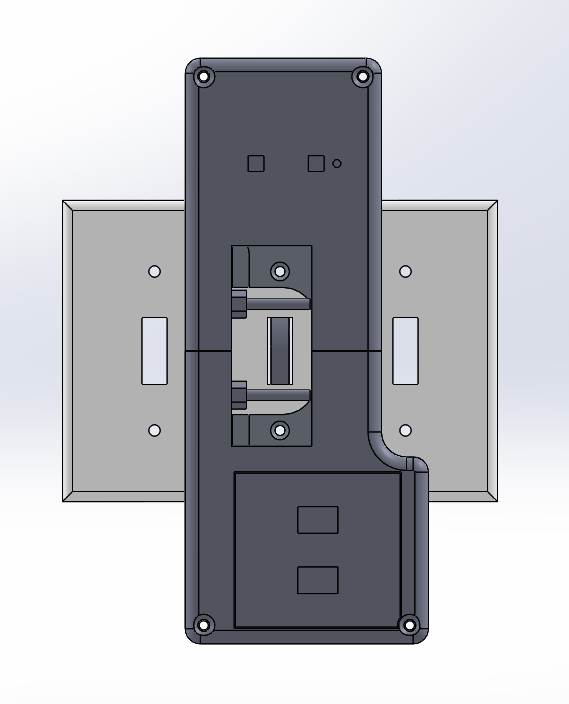
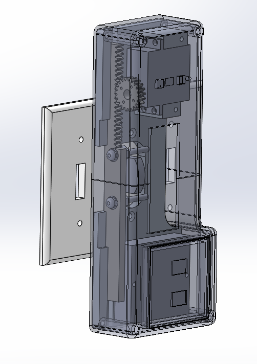
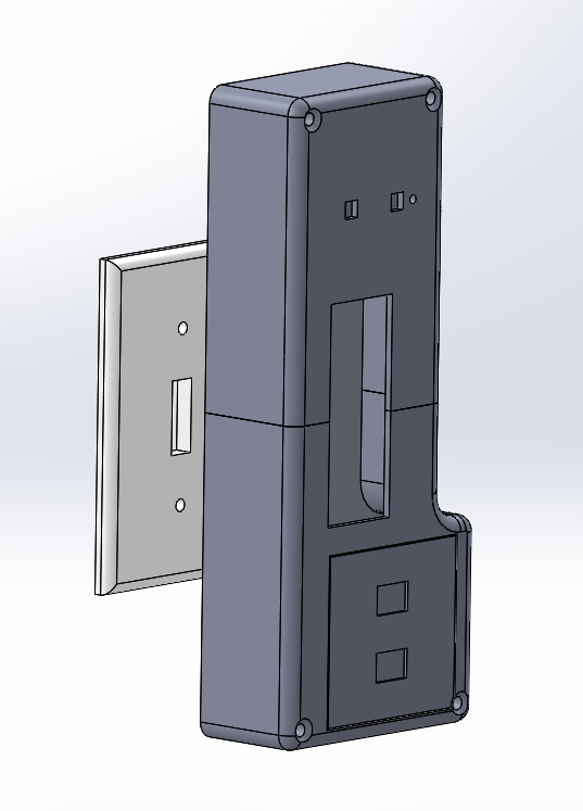
How this project would look mounted on a wall.
Narrative Sketch (How would Kathy use this?)
Kathy has just had a wonderful dinner with her guests and everyone’s had their fun but it’s getting late. She needs to see them out to her doorstep where guests can bid their farewells and head out to their cars, so she activates the Light Switch 2.0 attached to her porch light. Then, she returns upstairs to where she can watch them leave from her living room window. Because the light will automatically turn off in 10 minutes, she has no need to go back downstairs and turn the light off again. This saves her another trip down the stairs.
How we got here
One of our biggest hurdles was that meeting with Kathy was initially unfruitful; we struggled to grasp at a proper project idea. A series of further meetings confirmed a concrete idea, however.

Brunch at Kathy’s with the crew!
Our humble beginnings started with some very basic materials, starting from a plastic straw stuck on a servo.
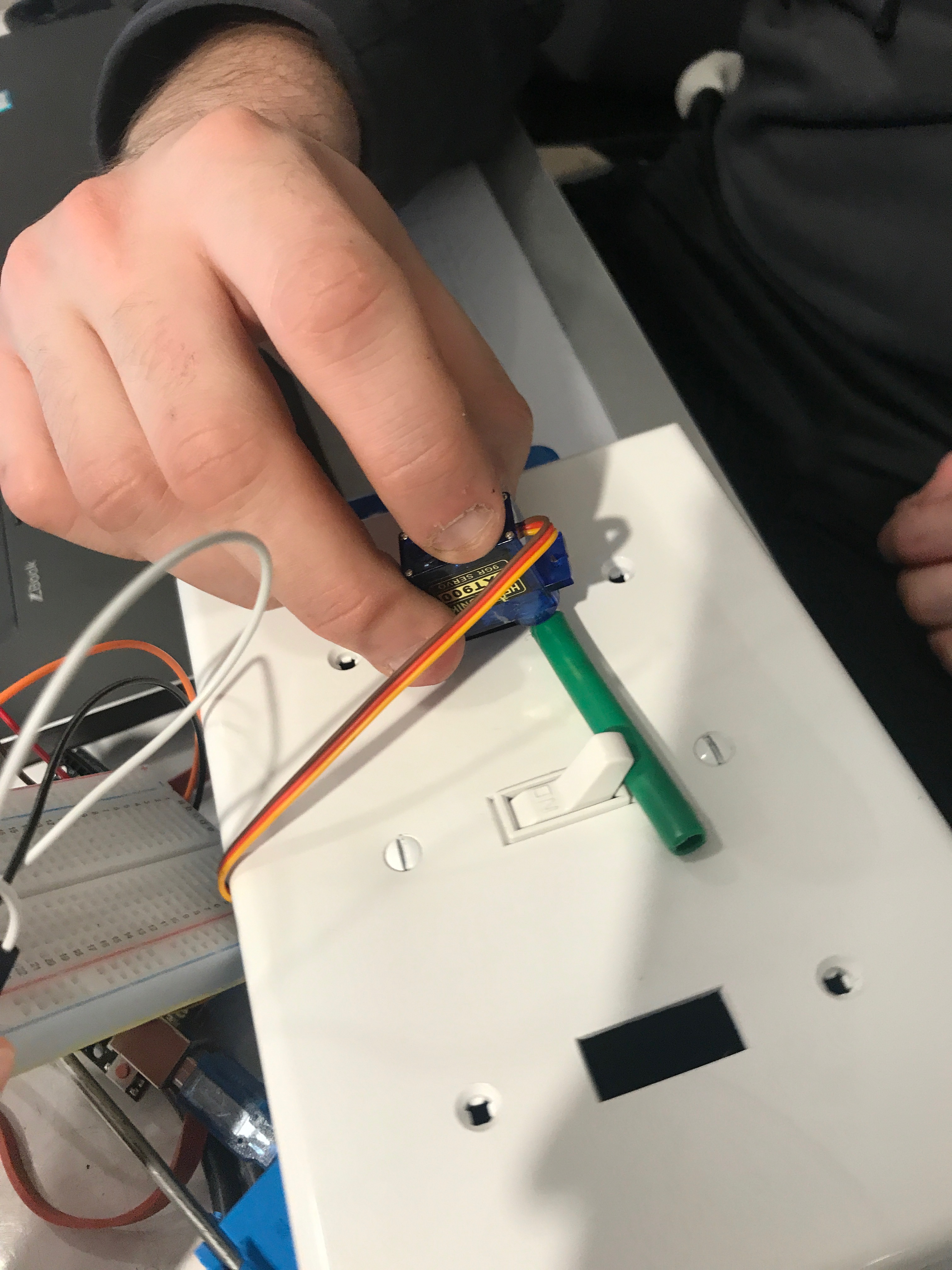
Servo testing. We tested for how strong the grip on the servos would have to be and how high.
We also cobbled together a bunch of Popsicle sticks for a stand as a sort of functional prototype holder.
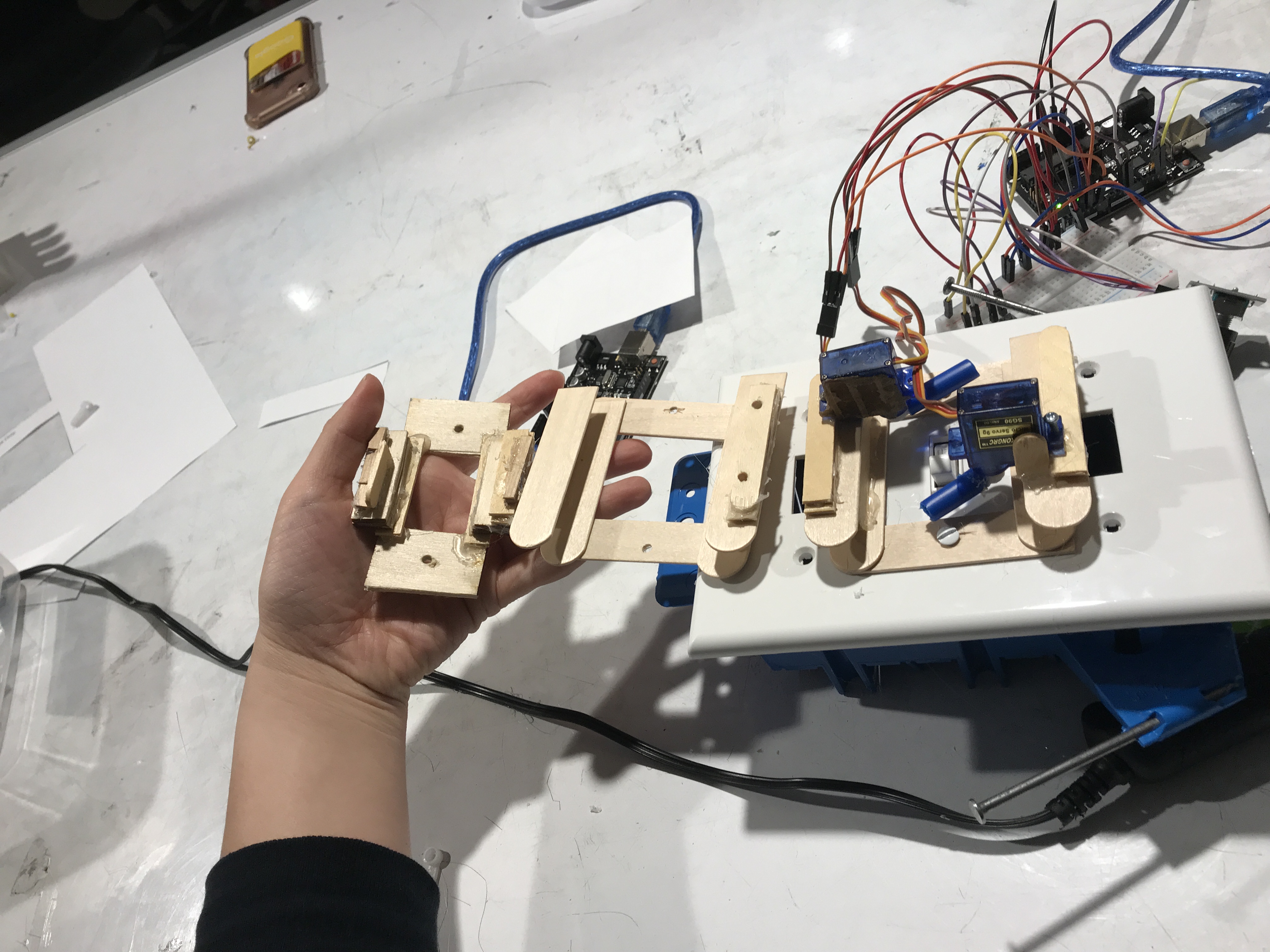 The progression of the temporary servo-holders.
Our work resulted in a simple, behaves-like functional prototype. It turned a switch on and off, but using simple and homely means, as well as with a few buttons, a rotary encoder, and a LCD screen.
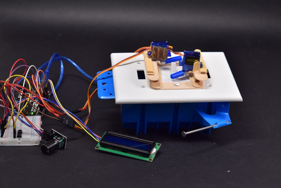
Where we stood with the prototype.

An early sketch of the new and improved project.
Predictably, the critique gave us valuable feedback to modify our project. Of course, we knew that our use of servos would have to be rethought. Originally our plans would have been to use a linear actuator but based on time and cost,we used gears and a servo to mock that functionality.
Based on prototype critiques made by Kathy, we ended up having to rethink the entire user interface of our project. We decided to limit the functionality of our item given that it was all we needed and frivolousness would have been in poor visual taste. No longer would we have so many moving parts; instead just a 10 minute hard-coded timer would replace the LED screen and rotary encoder.

Starting over from scratch. All the plans have completely changed, and we’re using a larger servo now.
A simpler process would replace the circular motion of our dual servos from the initial prototype. Using gears and a single powerful servo, we mimic a linear actuator to more reliably switch it on and off.

Final mechanism used to push the switch. Laser-cut out of acrylic.
We made a holder made out of metal, mostly courtesy of Justin’s CNC routing skills. It is to be the base for the system and the cover.

Metalworking for the cover via CNC routing.

The finished foundation. The servo runs the gear, which pushes the linear piece through the groove.
Despite some soldering problems, moving onto a more convenient proto-board helped wrap up the software side of things and enabled us to put all the pieces together. We used a set of four batteries to enable the user the most battery life possible, as it should last for a long time. This was at the expense of the visual appeal, as it added a bit more bulk to the overall product.

The piece with all the hardware in place.
We went through the critique coverless, but that was an issue we still wanted to address. For the cover we decided upon 3D printed plastic. We encountered a problem with button sizes, but ended up sanding the excess away. In addition, the panel was slightly short for the contents, but slightly. We decided upon hot glue to coax the seam a little more together.

The 3 pieces of the cover, screwed on.
Conclusions
Feedback from the Public
“Battery could be made smaller with a Lipo battery”
“Why batteries and not get it from house?”
Some concerns with the batteries arose during the critique. We had a few reasons for batteries over wall-switch power, mainly to do with the layout of the house, but it would be wise to consider batteries of smaller size. We wanted to maximize the power usage rather than minimize size, but if the size is that much of an issue, we would consider this for future iterations.
“Somewhat large/clunky box on light switch”
“Form function, Electronic vs mechanical.”
“more room for switch access.”
Many of the critiques centered around how large the box is attached to the switch. The bulk of the size is the battery and servo, and had we been able to locate smaller parts with the same or better functionality, we would have preferred to use those. If there was a method to better solve this problem with smaller parts or even at all smaller parts, we would gladly have it.
However, one piece of salient advice that we would consider in later iterations is the switch access, which could be perhaps solved with a different cover with lower walls.
“Not multiple timers.”
This functionality was voted off by our person, who wanted minimalism and functionality rather than more UI. We originally had an adjustable timer, but our client did not need it. Nevertheless, we agree that perhaps to make this overall a more useful product a way to change the timer would be helpful.
“Works, simple to use.”
“Nice machining. The lever to turn the switch on and off is sold and seems to be unaffected by electrical concerns.”
Much of the praise for the product centered around the mechanical and functional simplicity of our product. It comes at odds with the comment critiquing the simplicity of the product. I think we have settled in a good sweet spot for Kathy, but not necessarily for everyone, and perhaps in future iterations a small amount of tweaking could fix that.
“Sort of roundabout way of solving the problem, better solved by smart lighting.”
The discussion we had with Kathy regarding this problem could have been better answered by an electrician, but as we were not electricians, we could only help with an external mechanic. However, we agree: perhaps some wall-rewiring would also solve this problem.
Major takeaways
It was a really pleasant experience to work with Kathy on this. She made great effort to be helpful throughout our process, and we were able to discuss quite a lot. We really didn’t have any complaints about working with her. The only thing that may have smoothed the process over might have been a more set agenda when meeting with her, as we may have discovered other problems to fix earlier.
Regarding the build process, there were a few issues that could have been better addressed. First, the bottle-necking that parts-sourcing created gave us a schedule shift in a negative direction. We were preoccupied with finding a linear actuator to buy and ended up not using any. Had we decided on a servo automatically, the process would have been much more streamlined. In addition, some parts of the process take more time. and should have been considered. The 3D printed cover took a while to print, and therefore should have been allotted more time on the schedule, and having to create the servo mechanism put a lot of pressure on Justin. The group roles could also have been better assigned to maximize efficiency. Mechanical engineering provided the bulk of time-consuming process, and could have been a burden better shared.
Technical details
Code
/* This code controls a servo motor to flip a light switch
 *  after 10 minutes or on demand depending on which button
 *  is pressed.
 *  Components:
 *  1 x 270 degree servo motor
 *  2 x tactile momentary push buttons
 *  1 x LED
 *  Inputs: button presses
 *  Outputs: blinking LED, servo motor movement
 */
const int START = 2;
const int MANUAL = 4;
const int SERVO = 3;
const int LED = 1;

unsigned long timer = 0;
bool state = false;
bool start = false;

void setup() {
  pinMode(SERVO, OUTPUT);
  pinMode(MANUAL, INPUT_PULLUP);
  pinMode(START, INPUT_PULLUP);
  pinMode(LED, OUTPUT);
}

void moveUp() {//turn light switch on
  int i = 0;
  while (i < 100) {
    digitalWrite(SERVO, HIGH);
    delayMicroseconds(2000);
    digitalWrite(SERVO, LOW);
    delay(10);
    i++;
  }
  resetServo();
}

void resetServo() {//reset to middle resting position
  int i = 0;
  while (i < 100) {
    digitalWrite(SERVO, HIGH);
    delayMicroseconds(1200);
    digitalWrite(SERVO, LOW);
    delay(10);
    i++;
  }
}

void moveDown() {//turn light switch off
  int i = 0;
  while (i < 100) {
    digitalWrite(SERVO, HIGH);
    delayMicroseconds(600);
    digitalWrite(SERVO, LOW);
    delay(10);
    i++;
  }
  resetServo();
}

void blinkLED() { //function that blinks an LED 4 times
                 // to indicate that the timer has started
  digitalWrite(LED, HIGH);
  delay(100);
  digitalWrite(LED, LOW);
  delay(100);
  digitalWrite(LED, HIGH);
  delay(100);
  digitalWrite(LED, LOW);
  delay(100);
  digitalWrite(LED, HIGH);
  delay(100);
  digitalWrite(LED, LOW);
  delay(100);
  digitalWrite(LED, HIGH);
  delay(100);
  digitalWrite(LED, LOW);
}


void loop() {
  //state = true when light is in ON position and false
 // for OFF position
  if (!digitalRead(MANUAL)) {
  /* Check to see if the manual operation button has been pushed.
   * If it has, turn the light on or off depending on previous state.
   */
    if (state) {
      moveDown();
      state = false;
    }
    else {
      moveUp();
      state = true;
    }
    /* If manual button was pressed before the 10 minutes have passed
     * after pressing the start button, the timer is overrided and manual
     * light switch operation is enabled.
     */
    start = false;
  }
  if (!digitalRead(START)) {
  /* When the start button is pressed blink the LED and begin
   * the timer
   */
    blinkLED();
    start = true;
    timer = millis();
  }
  if (start) {
    if (millis() - timer >= 600000) { //check to see if 10 minutes have passed
      moveDown(); //if 10 minutes have passed, turn light switch off
      timer = millis(); //reset timer
      state = false;
      start = false;
    }
  }
}
Schematic and design files

Comments are closed.