In March 2019, our student group began working on the final project for our introductory physical computing course. Our task: to design a build a useful device for an older man named Mark, a student at Osher. We built a simple machine to help Mark transport food from his oven to his countertop.
This blog post summarizes our entire journey, where we landed in the end, and what we learned along the way. You can read our other blog posts for a detailed account of our first meeting with Mark, and further explanation of our prototyping process.
The Team: Mark, Katie McTigue, Stefan Orton-Urbina, Nina Yoo

Mark in his home office
What We Built
The Problem
Mark has difficulty taking things out of his oven and moving them over to his countertop. Some of the factors contributing to the problem are the weight of the baking tray, the distance across the kitchen, and the oven door blocking Mark from getting his wheel chair closer to the oven rack.
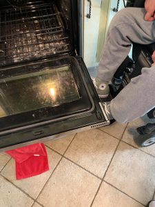
Mark demonstrating how the oven door blocks him from getting close to the rack
The Solution
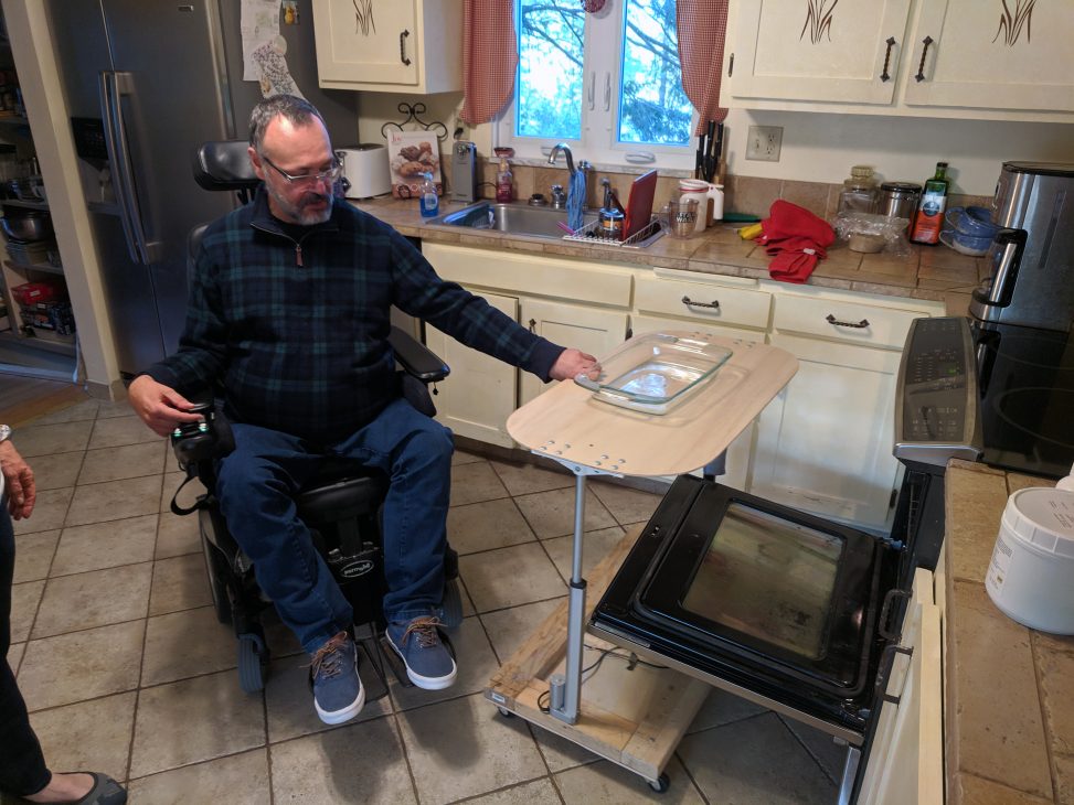
We built a rolling cart with a simple machine that moves a baking tray (or anything else that is placed on it) up and down. The cart is sized to fit over the oven rack with the oven door open so that Mark can slide the tray onto the cart without much effort.
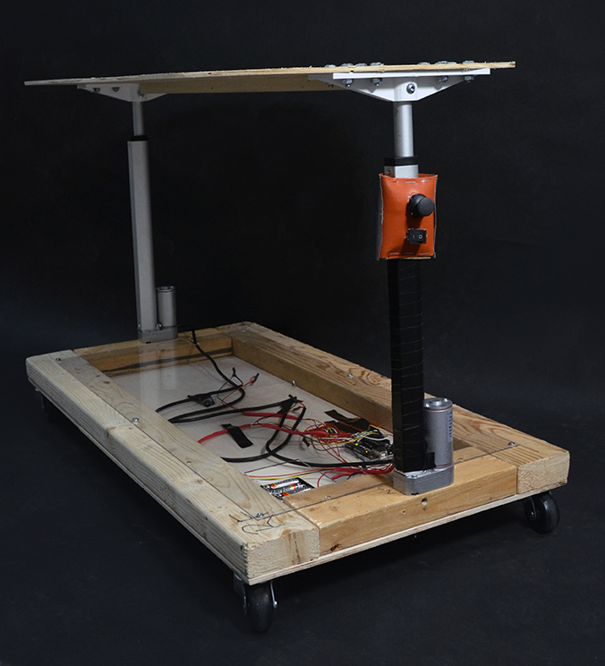
The Oven Elevator at a slightly raised position.
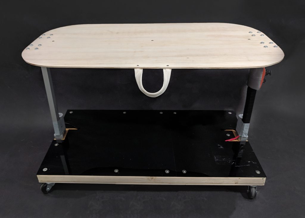
The device after we added the final touches of an acrylic cover and handle.
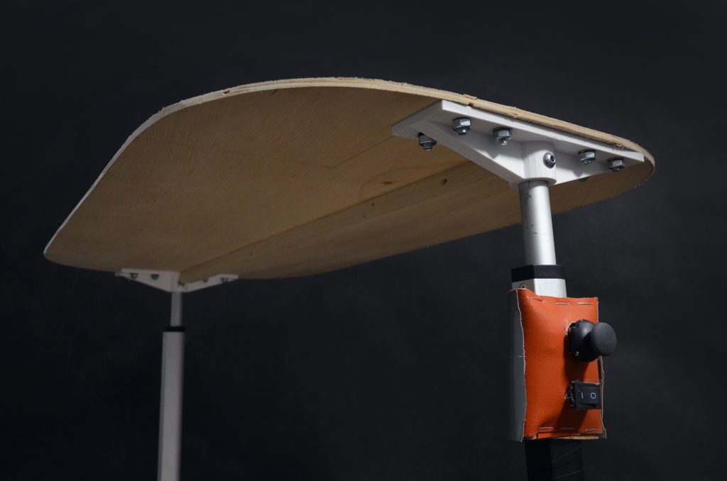
The tapletop, attached to the linear actuators with custom 3D printed braces.
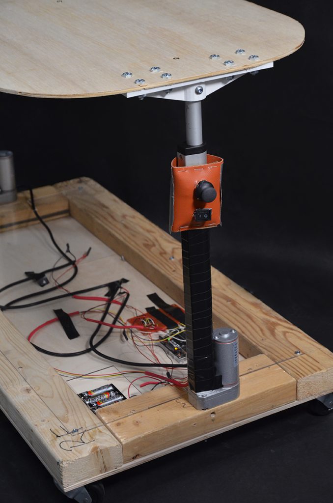
The joystick control and on/off switch.
What Does This Look Like?
The following is a scenario of use based on Mark’s daily life.
Mark is baking asparagus for dinner. He cuts and seasons the dish on his counter, and moves it onto the baking tray. He pulls his oven elevator cart out from under the counter where he stores it, and pushes the joystick up to raise it to the height of the counter. He pulls the tray onto the cart, and pulls it behind his wheelchair over to the oven. He opens to oven door, pulls out the oven rack, and pulls the cart over it. Then he pushes the joystick down to lower to the cart top to the height of the oven tray, and pulls the baking tray onto the rack. He rolls the cart away and closes the oven door.
When the dish is done cooking, he reverses the process to get the tray back to the countertop. Dinner is served without Mark ever needing help from his wife Renée!
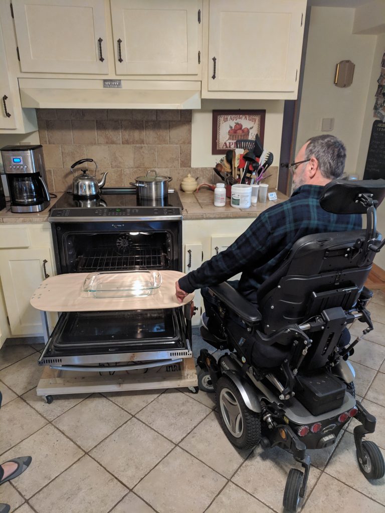
Mark pulling the device onto the oven.
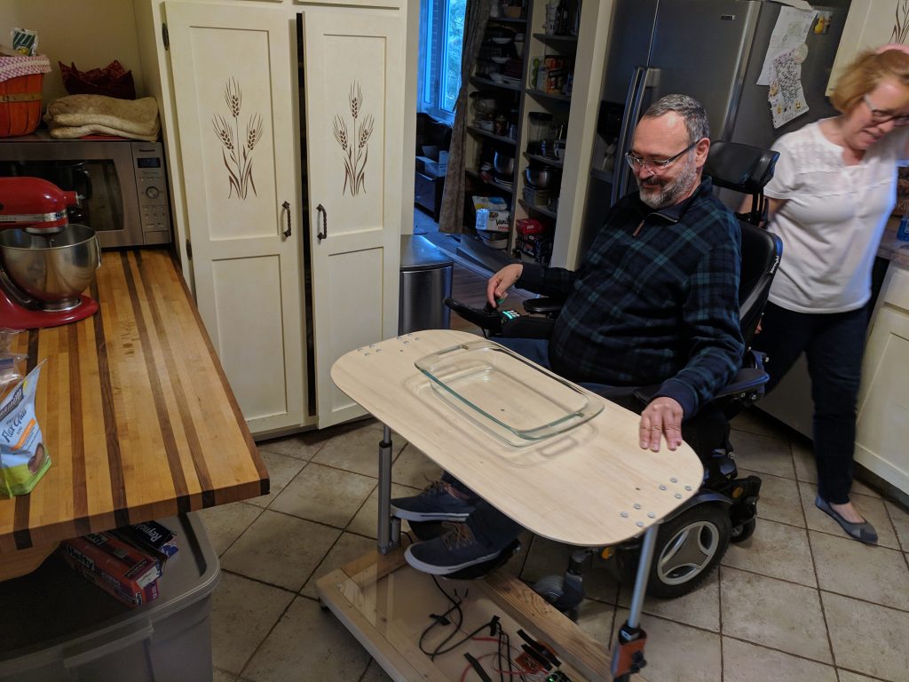
Mark moving the device over to his countertop.
How We Got Here
This process was a humbling experience for all of us. The overall trend was that we started with a very ambitious design and it got simpler and simpler as the weeks went on. In the end the big success was that we were able to get our scope down to something that we could execute in the allotted timeframe, and build something that (we believe) will actually solve Mark’s problem.
Scoping
We had a lot of ideas for features that we thought could help Mark. In our early discussions we considered:
- In-and-out motion for the tabletop in addition to the up-and-down motion, so that Mark wouldn’t have to work to pull the tray onto the top.
- Making the whole cart a remote-controlled device that could wheel around as directed, so that Mark would not have to pull/push it across the kitchen.
- Making the control a handheld remote that is separate from the cart.
- A rechargeable battery that can be plugged in.
These are all features that were sacrificed with Mark’s blessing in order to really perfect the core up-and-down functionality, user experience, and durability of the device.
Our First Design
Because the device needed to fit over the oven door and reach the baking tray, our natural inclination was to make a tabletop surface that was connected to the base on one side and open on the other. Our goal was to maximize the ease of rolling the device up to the oven rack.
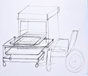
An early sketch of the one-sided model, with the oven door sandwiched between the top and bottom levels.
We had several ideas for engineering the mechanism that would move the tabletop up and down, including a belt with two small motors. In the end we decided the simplest approach would be to use a linear actuator— a machine with a motor that crates motion in a straight line. The linear actuator would be supported by two rails on either side, hopefully creating enough stability for the platform to stay in place and support the weight of food.
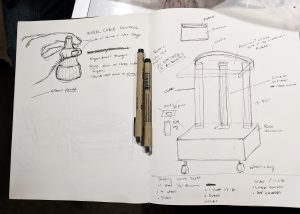
An early attempt at scaling out the device and planning materials.
Prototyping and Problem-Solving
We built two prototypes. The first was a “works-like” prototype: a simple demo of the actuator going up or down as two pushbuttons are depressed. The second was a “looks like” prototype, built our of foamcore to one quarter scale.
Stefan wiring the linear actuator.
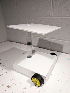
The “looks like” prototype. A plastic syringe came in handy for quickly mimicking a linear actuator.
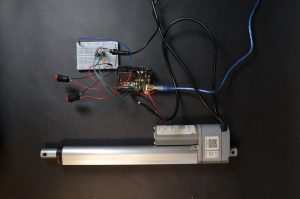
The “works-like” prototype.
We sat down with Mark to let him handle the prototypes and see if he thought we were on the right track. The “looks-like” prototype was very helpful to him in understanding what we had in mind, and he gave us positive feedback.
A Little Crisis and a Big Redesign
After the relative success of our low-fidelity prototypes, we were eager to plan out the details of materials and start building something more high fidelity. At this point we quickly realized that we might be a little over our heads when it came to structural engineering. Getting the top platform stable with support from only one side was a very real challenge with very real risks if we got it wrong; a 400 degree baking tray falling on Mark was a scary thought.
Nina came up with an idea to simplify the design significantly. We would attach two linear actuators directly to the tabletop, one on each side. We would space them far enough apart for the oven door to fit between them when open. The device would be symmetrical, and could be rolled onto the oven from either side.
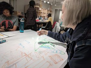
Nina sketching the oven elevator 2.0.
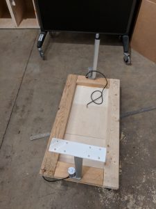
Mounting the two linear actuators.
Choosing the Controls
Now that we had a game plan for the mechanical components, we could invest some time in choosing the controls for turning the device on and off, and moving the platform up and down. We had a pretty complete picture of Mark’s motor skills with his hands and fingers, because in our first meeting with him we had extensively discussed both how he controlled his wheelchair, and how he used a keyboard and mouse.
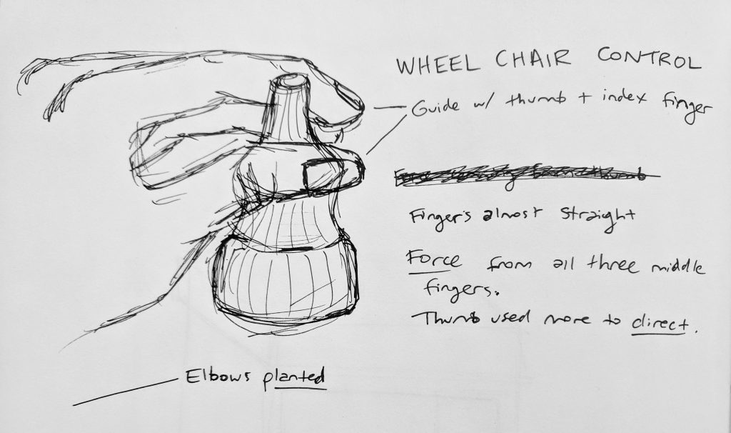
Notes on how Mark controls his wheelchair.
In our first meeting with Mark, he explained the symptoms of his acioscapulohumeral muscular dystrophy to us in the context of what he could and couldn’t do comfortably while playing a videogame:
| Can | Difficult | Can’t |
| Move hand and click (+ right click) | Pick up objects | |
| Move one finger | Move objects | Use all fingers at the same time |
| Move arms | Use a keyboard (do it with one finger) | Type with two hands |
| Move thumbs | ||
| Pull objects behind wheel chair. | Push objects (use feet) |
To control the platform, we chose a joystick that closely resembled the one Mark used to control his chair. We mounted it on the side of the cart at a height that Mark could reach comfortably. Because it is attached to the vertical pole of the linear actuator, it is simple to use as “up for up” and “down for down.”
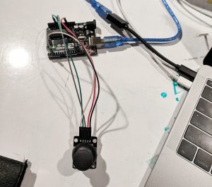
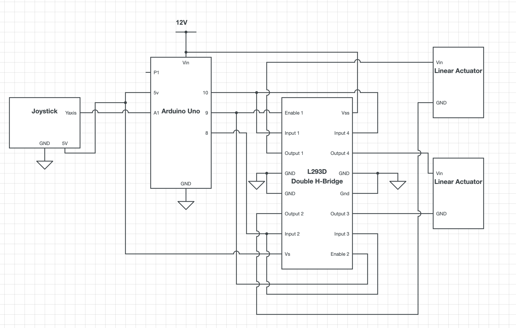
Programming the joystick to control the linear actuators.
Fabrication and Final Touches
Essential components of our final product:
- Custom-cut tabletop made of 1/4 inch plywood
- Wooden base made from 2x4s and 1/4 inch plywood
- 2 braces to attach the tabletop to the actuators (3D printed)
- 1 acrylic cover to protect the electrical components (laser cut)
- 1 joystick and 1 standard on/off switch
- 8 double A batteries and a plastic battery holder (8 batteries will power the device for ~60 minutes of use!)
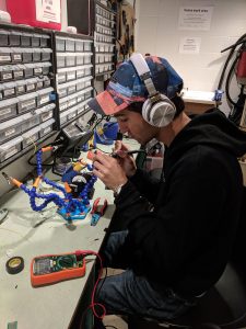
Stefan soldering.
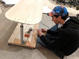
Stefan testing the actuators post-soldering.

The lasercutting file for the acrylic cover which fits over the base protecting the electrical components.
Conclusions and Lessons Learned
While making the Oven Elevator, we learned a few things in the process. One of the biggest setbacks that we went through, as mentioned before, was the reality of our design and how we were going to build it safely for Mark to use. Instead of taking the time to create a prototype on SolidWorks, or some sort of 3D emulator, earlier, we were more intent on starting to build. This caused us to go back on our designs multiple times due to the severity of budget, safety, and time remaining. We could have possibly saved us time if we spent more time working on fabricating a prototype to get an idea of how it works rather than just aiming to build in one go/ hoping it will work. Another lesson that was learned during the process, is to constantly be able to see from Marks point of view. During the process, we had a lot of design iterations, in drawings, where we struggled to decide on how we should implement a handle for Mark to use. This was more difficult to tackle than we assumed because we could not see Mark often so we needed to remind ourselves to think about how Mark may use it/difficulties for Mark that may occur. However, despite not having to meet with Mark often, we closely noted down what Mark wanted and made sure to fit his needs into our design. This caused us throw away previous ideas that we had, but having Mark give us his opinion gave us a firm direction to follow.
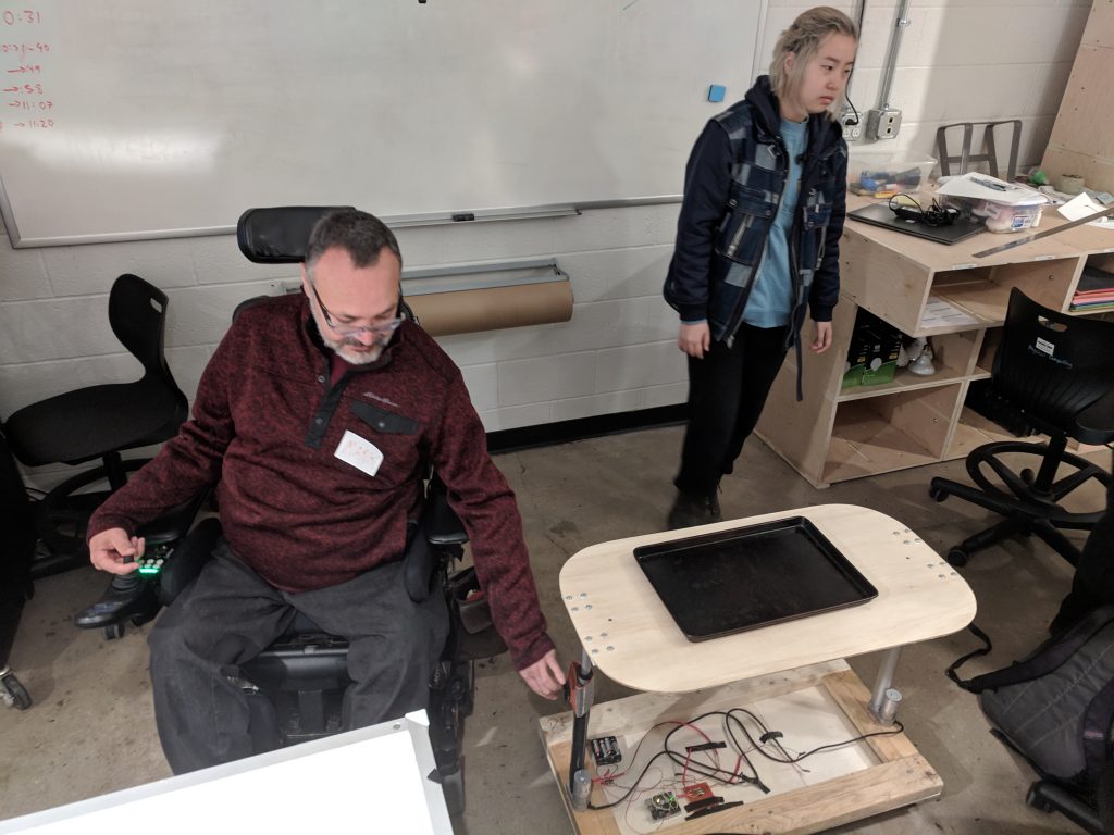
Mark testing out the oven elevator for the first time
Technical Details
Code
/*
   Oven Elevator
   Katie McTigue, Stefan Orton-Urbina, Nina Yoo

   Summary:
   We read the y-axis of a joystick, and move two linear actuators
   up and down in synchrony accordingly. The actuators move at a
   steady pace for as long as the joystick is pointed in one direction.
   The actuators stop on their own mechanically if they reach the
   minimum/maximum extension.

   Inputs:
   1 Joystick

   Outputs:
   2 Linear Actuators
*/

//Linear actuator vars
#define EN 9
#define MOTOR1 8
#define MOTOR2 10

#define BUT1 2
#define BUT2 3

//Joystick vars
const int SPEAKPIN = 2;
const int YPIN = A1;
const int MIDDLEPOINT = 507;
const int MARGINOFERROR = 5;

//Note: X axis pin is not needed, and doesn't even need to be wired

void setup() {
  Serial.begin(9600);
  pinMode(EN,OUTPUT);
  pinMode(MOTOR1,OUTPUT);
  pinMode(MOTOR2,OUTPUT);
}

void loop() {
  //Read Y pin of joystick
  int yVal = analogRead(YPIN);

  //Move up for as long as the joystick is pointed up
  if (yVal < (MIDDLEPOINT - MARGINOFERROR)) {
    Serial.println("Go Up");
    digitalWrite(MOTOR1,LOW);
    digitalWrite(MOTOR2,HIGH);
    digitalWrite(EN,HIGH);
  }

  //Move down for as long as the joystick is pointed down
  else if (yVal >= (MIDDLEPOINT + MARGINOFERROR)) {
    Serial.println("Go Down");
    digitalWrite(MOTOR1,HIGH);
    digitalWrite(MOTOR2,LOW);
    digitalWrite(EN,HIGH);
  }

  //OFF
  else {
    digitalWrite(EN,LOW);
  }

}
Comments are closed.