Introduction
This semester, we had the opportunity to work with a group of older people who attend OSHER Lifelong Learning Institute at Carnegie Mellon University. We collaborated with Lois, one of the OSHER students, and after an in-house interview where we discussed her needs and daily routine , we designed a volume regulator for her television. Often at night, when she watches TV with her husband Irv, the volume of the commercial is much louder than the volume of the regular TV program. To solve this problem, we decided to create a device that uses IR signals to interact with her TV. When the TV gets too loud the device automatically turns down the volume. After 30 seconds, or by pressing a button, the device is able to turn the volume back up.
Link to:
Final Device
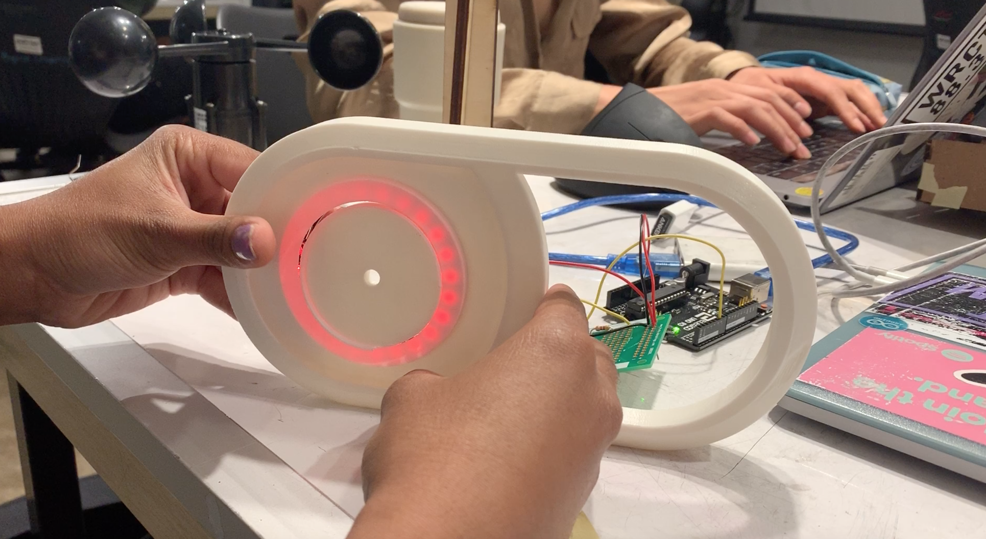
The device is designed to sit on the table in Lois’ den positioned directly in front of the television. The device will listen and if the sound that it hears is continuously above a threshold for a period of time, it will send IR codes to the TV to lower the volume. After 30 seconds, the TV will send signals to raise the volume back up, presuming that the TV commercials have ended and the regularly scheduled TV program is back on.
Using the knob, Lois can change the threshold of the volume that she would like the TV to be set to. The button on top, is in some ways an override button. If for some reason the volume is lowered due to background noise, or the commercials end early, Lois can press the button to switch it to the other state. The device uses a 5V cable to connect to power and has a rocker switch to turn the device on/off.
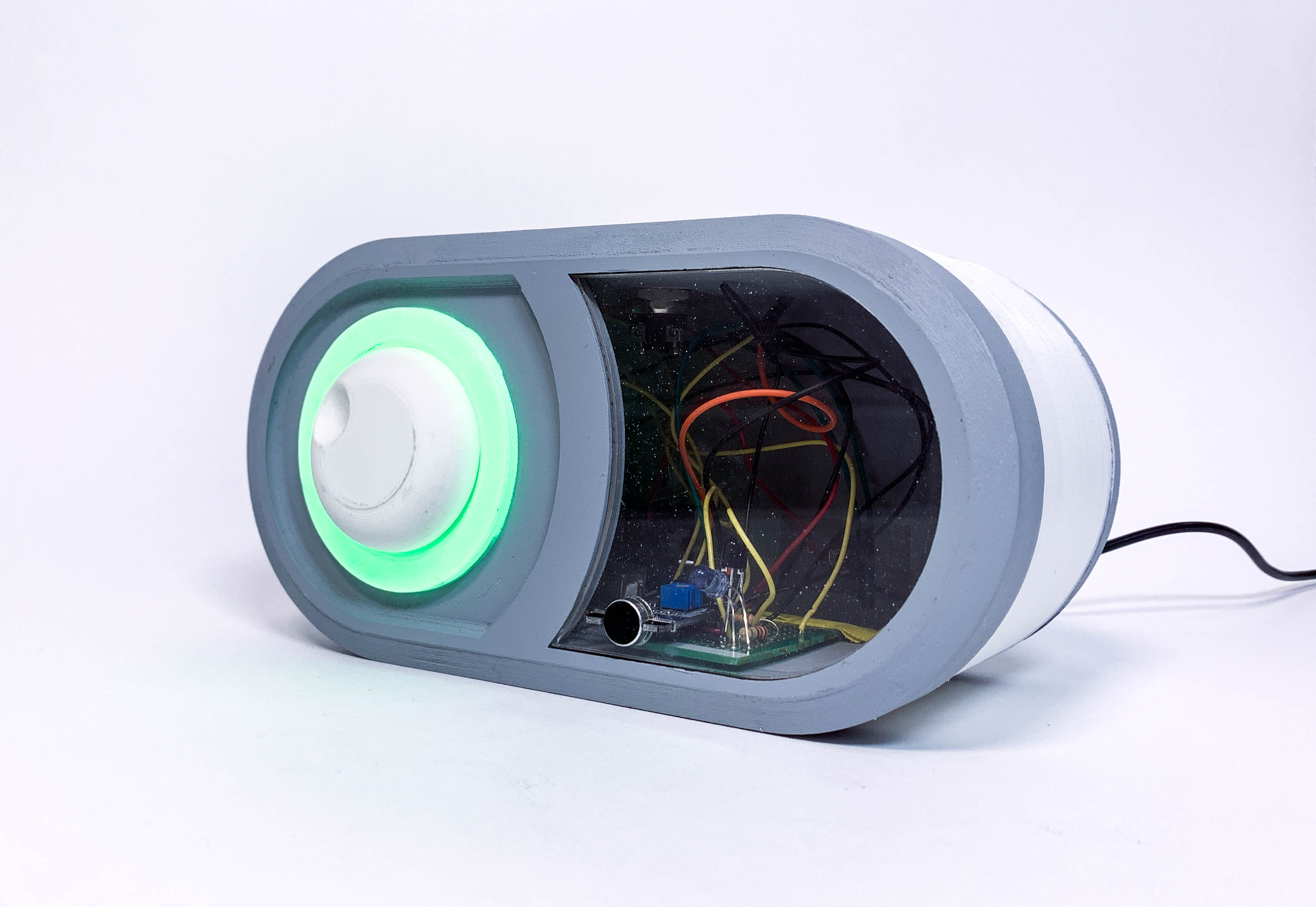
Device as volume is being lowered: NeoPixel flashes green
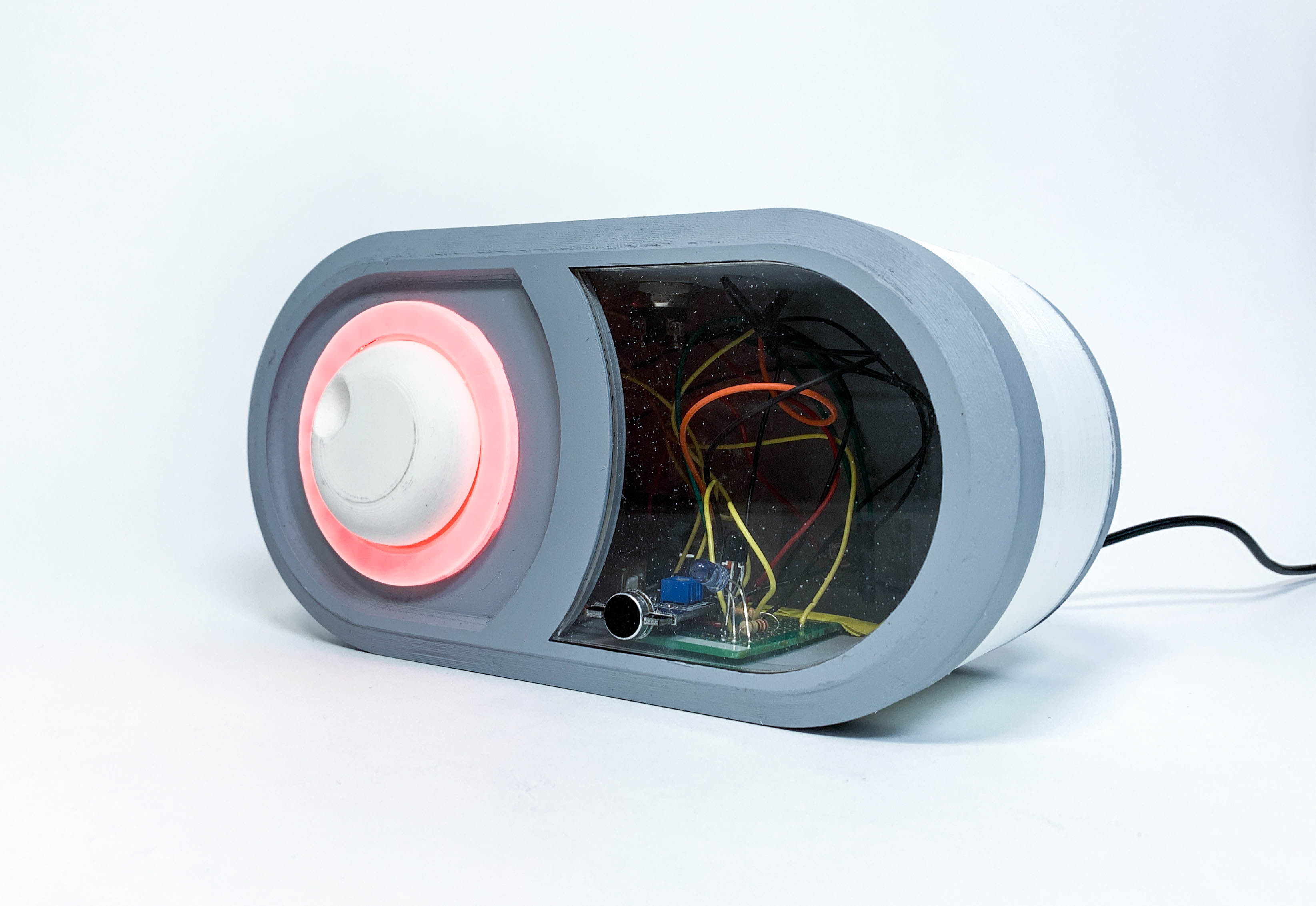
Device as volume is being raised: NeoPixel flashes red
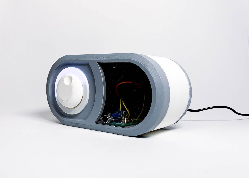
Device as volume threshold is set: NeoPixel illumination indicates the volume threshold as the knob is turned
Pushing the button on top to lower the volume, the NeoPixel flashes green to indicate that signals have been sent to the TV to lower the volume
Pushing the button on top to raise the volume, the NeoPixel flashes red to indicate that signals have been sent to the TV to raise volume again
Adjusting the knob on the device to change the threshold of the volume, NeoPixel adjusts to serve as a visual indication of what the threshold is.
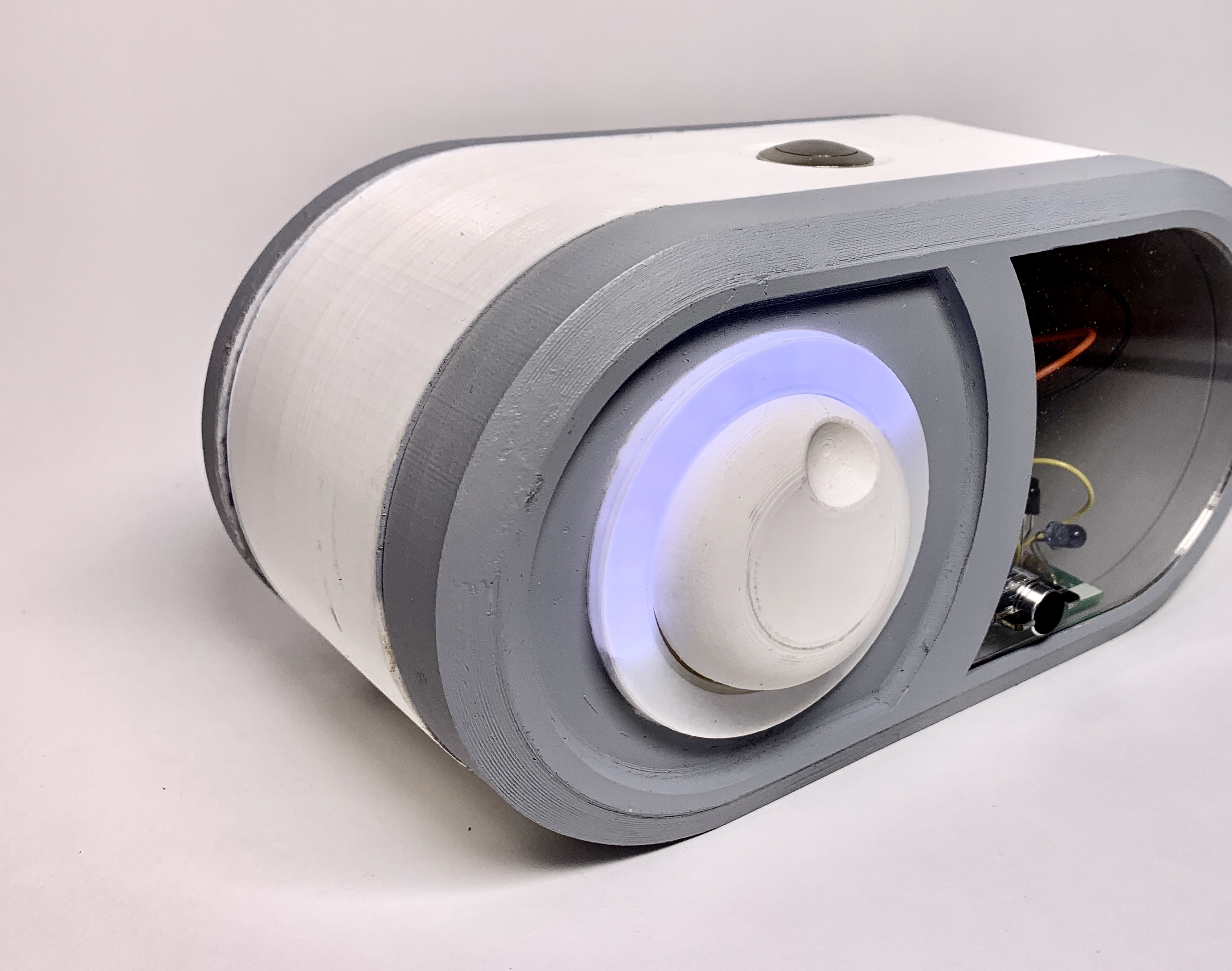
Knob and Neopixel: The NeoPixel ring is a visual indication of what the device is doing: Lois wanted green to indicate that the volume is being lower, and red to indicate that volume is being raised. The white gives a visual representation of the volume—the knob is designed for ease of adjustment of volume.
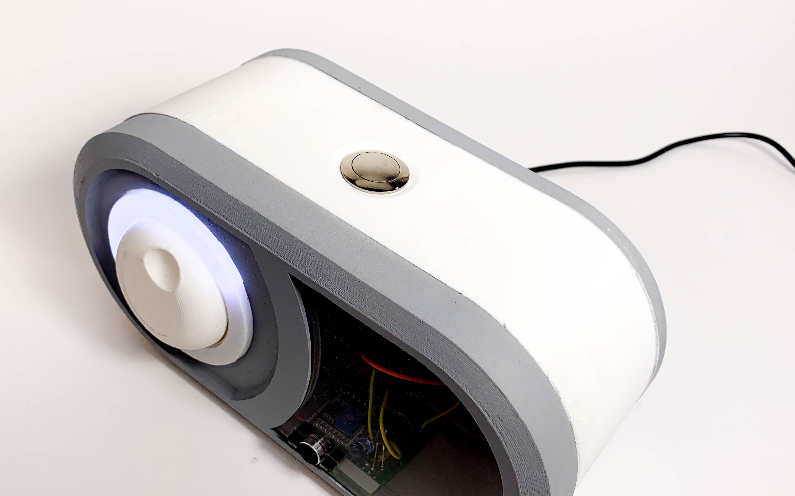
Button: Button on top that can be pushed by Lois to change what signals the IR transmitter is sending
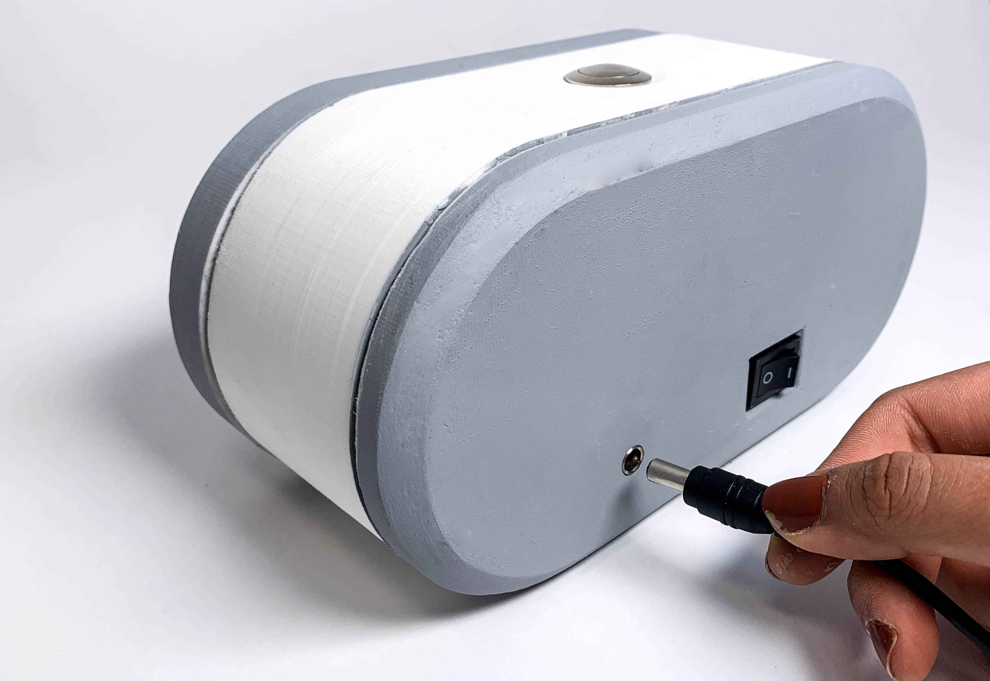
5V input: in order to allow Lois to use this in her den, we wanted to connect to a power outlet
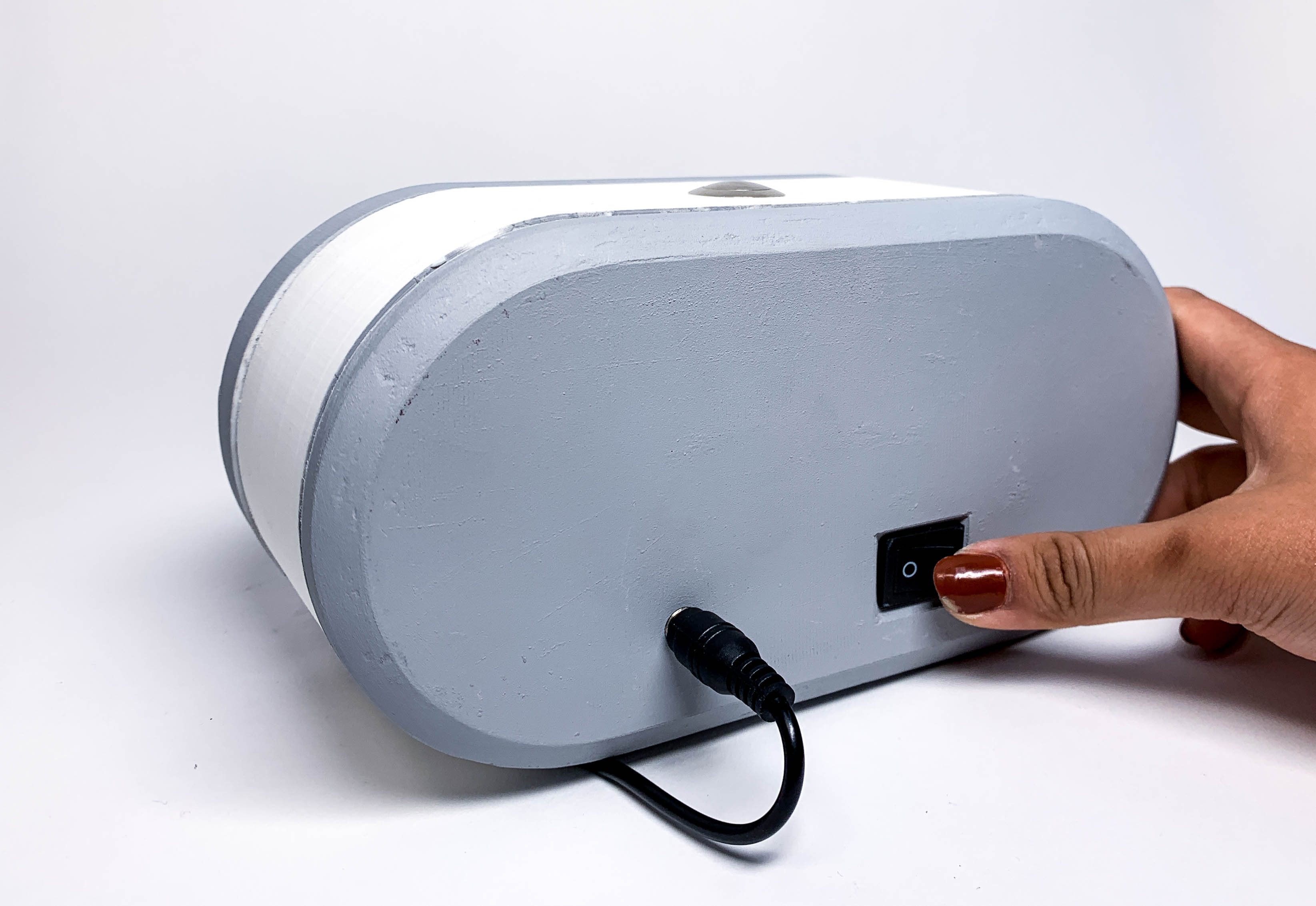
Rocker Switch: Turns the device on/off without having to unplug the device
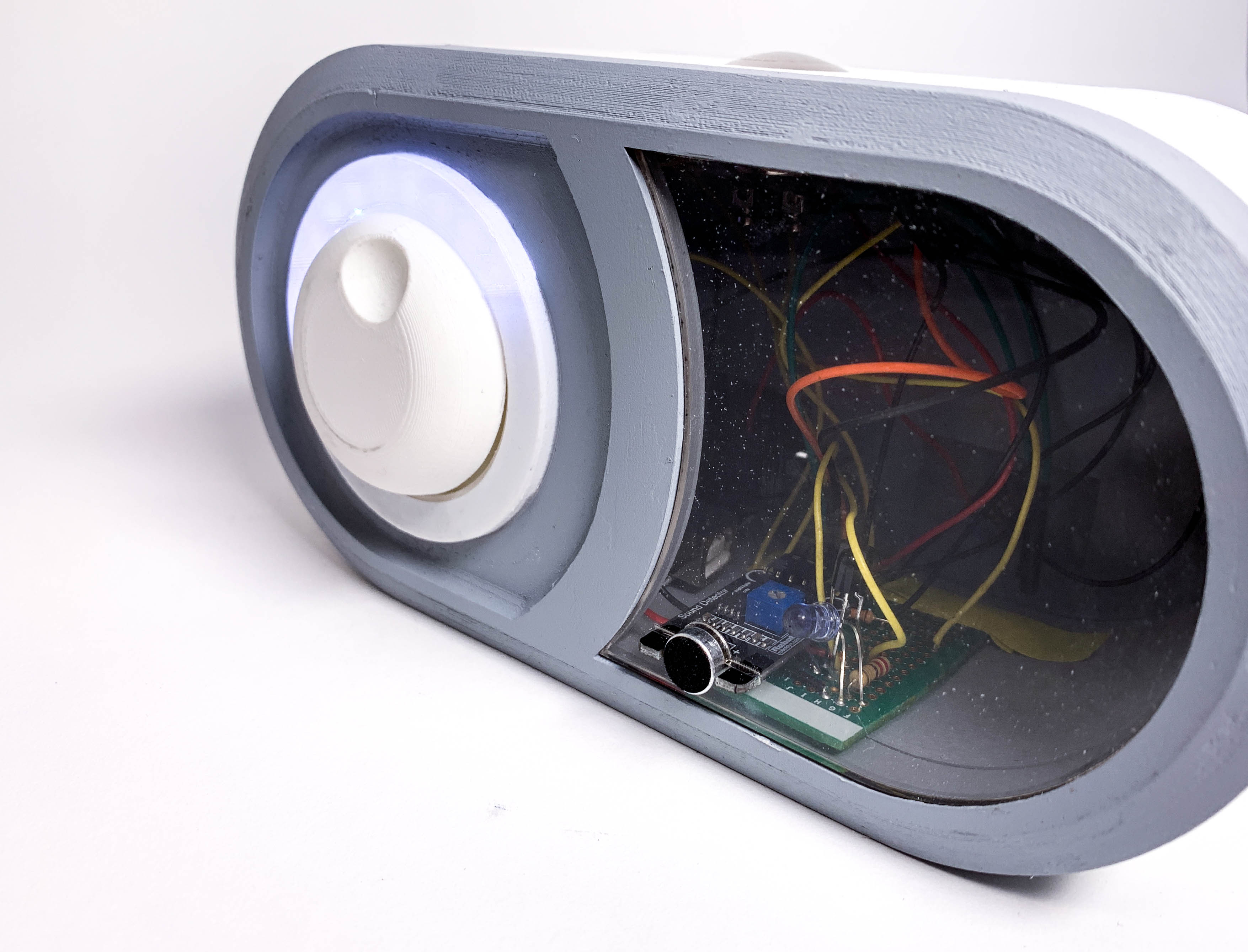
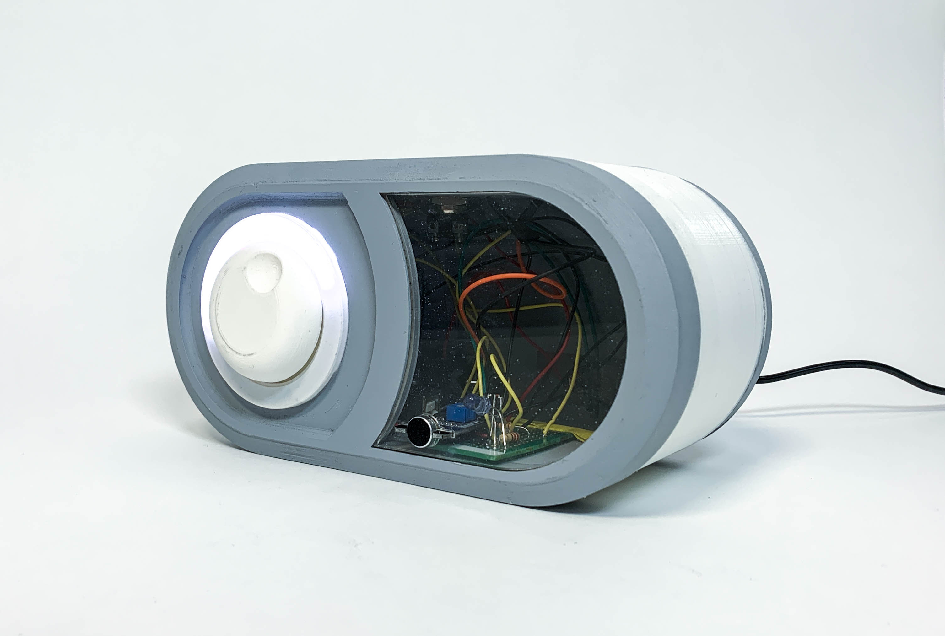
IR Transmitter: The clear acrylic is meant to allow the IR transmitter to send the signals, and since IR cannot send signals through opaque acrylic we decided to use clear.
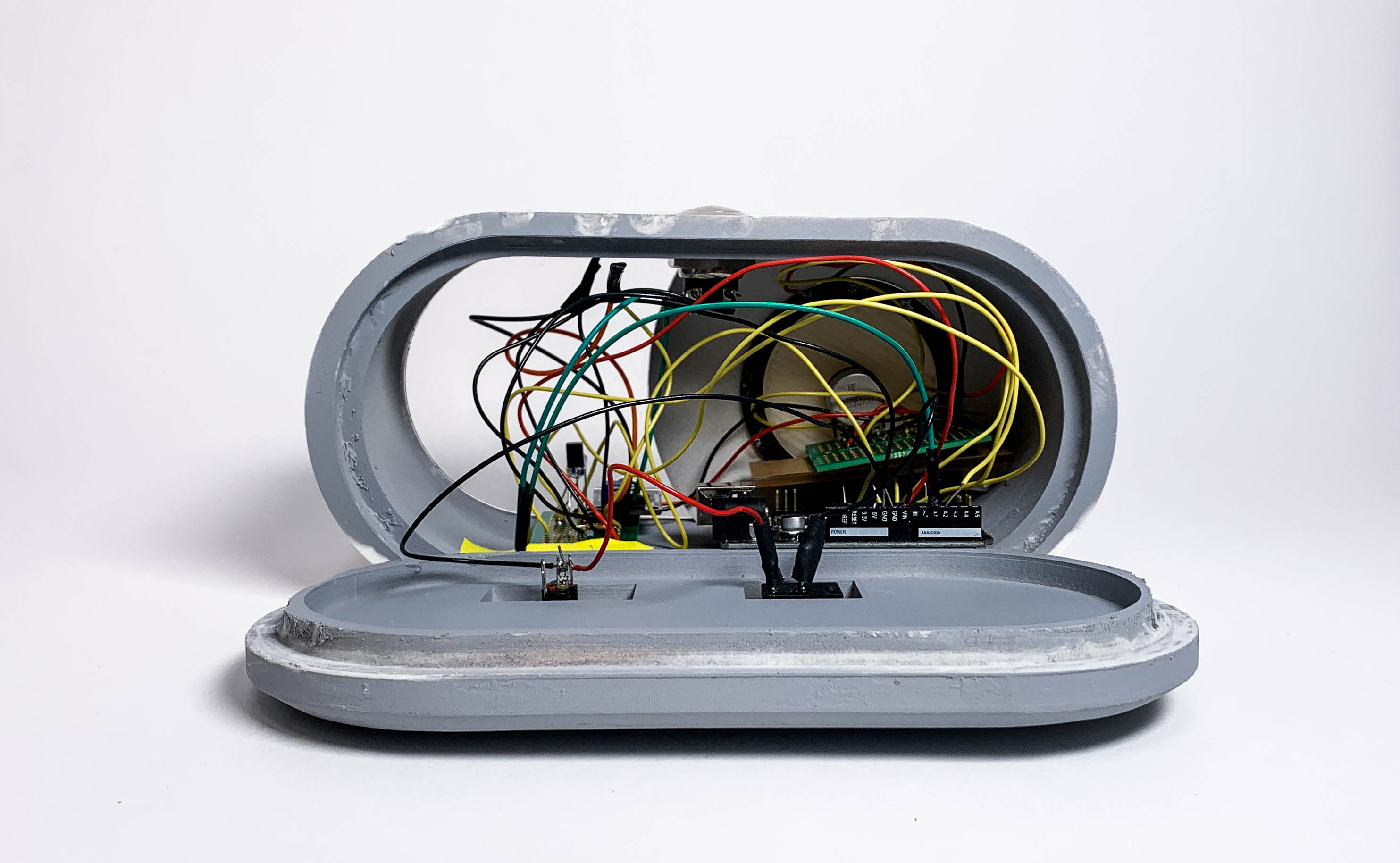
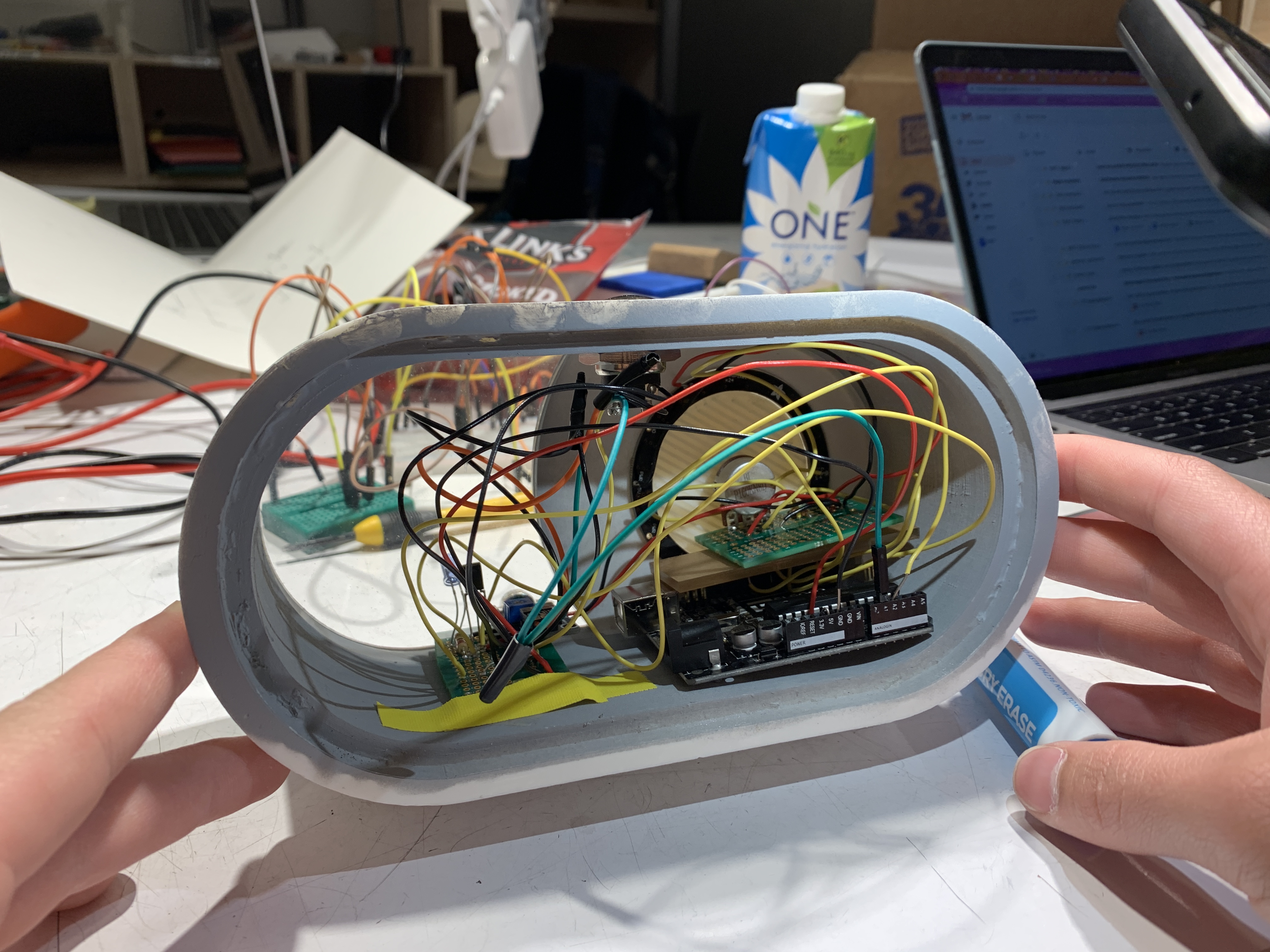
Opened device: The wiring and the internal components of the device
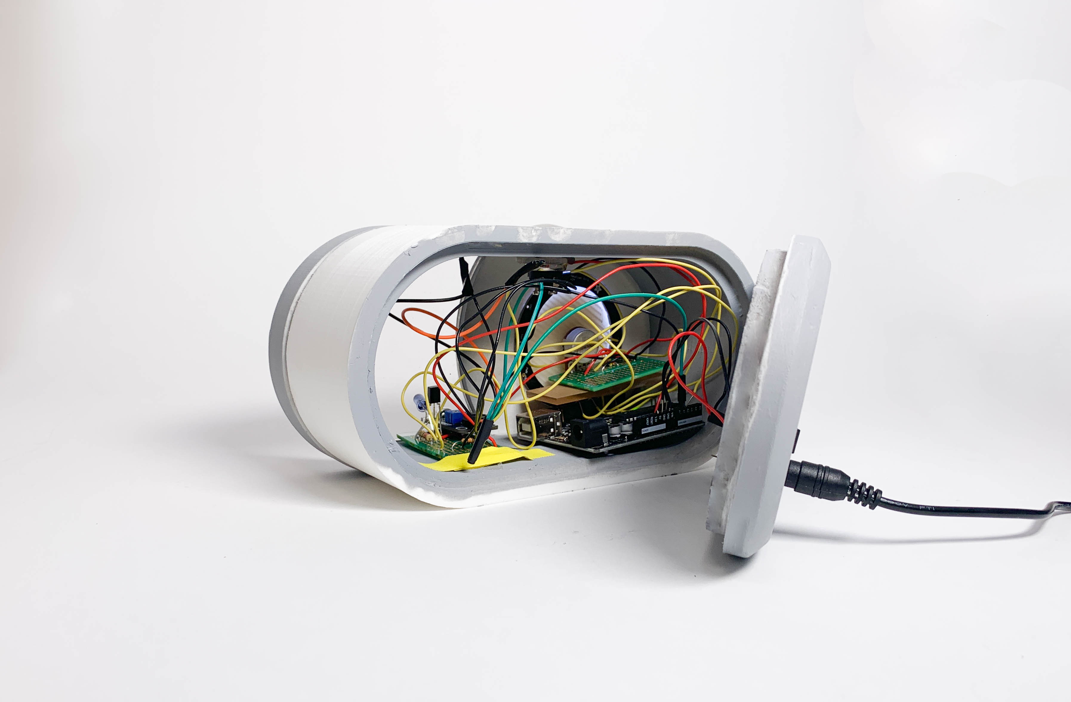
Close up of internal electronics—notice the placement of the two breadboards: one is for IR transmitter and sound sensor while another is placed for the potentiometer knob above the Arduino
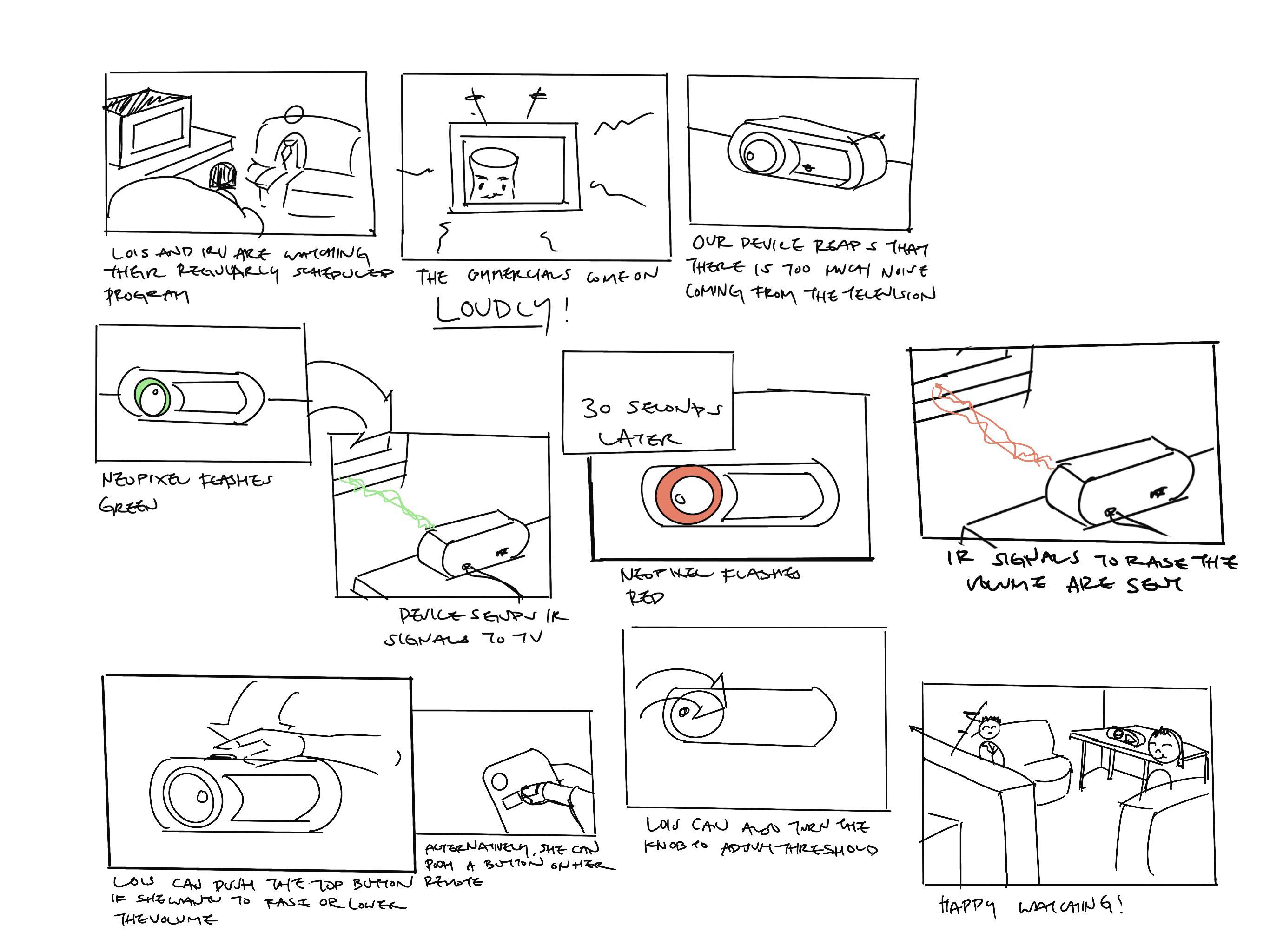
Narrative sketch of intended use
Process of Creating
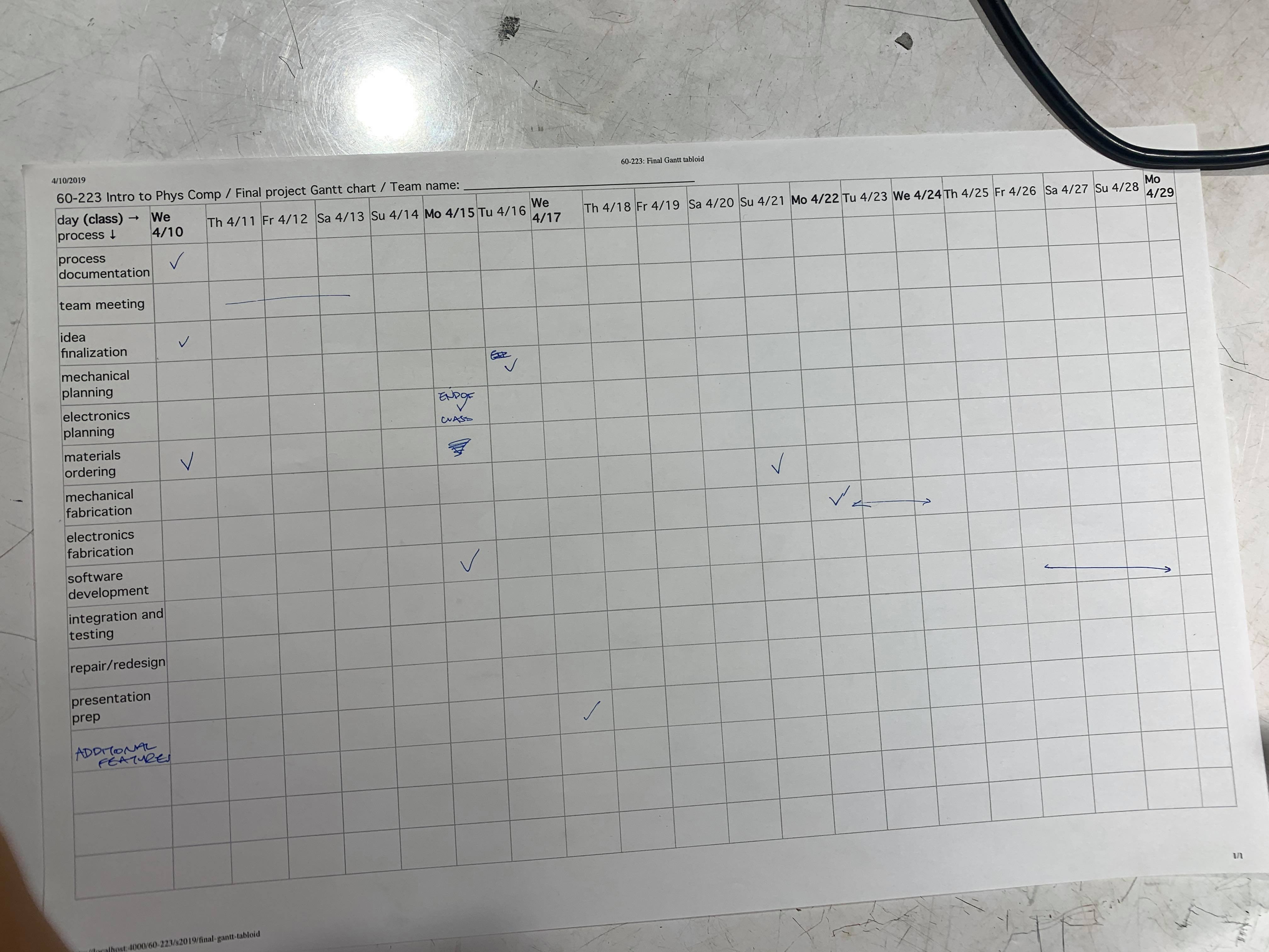
Gantt Chart to help us organize our pathway leading up to the final critique
In terms of planning out our steps towards our final prototype, we were pretty on schedule with most of our plans. We started the actual building early on, so we were on schedule in that respect. We had some delays with the shipping of parts, and had some difficulty accurately sensing loudness. These drawbacks meant we didn’t finish a lot of our circuitry and code until the last four days. However, because some aspects of the physical final device (3D prints) did not depend on the finalization of the code and internal circuitry, we were able to continue moving forwards on all aspects of the project.
After the critique during the first prototype, we wanted to switch from an LCD screen to a more basic visual so that Lois wouldn’t need to get too close to the device to understand what it was doing–after brainstorming we determined that would be the NeoPixel would be a good alternative.
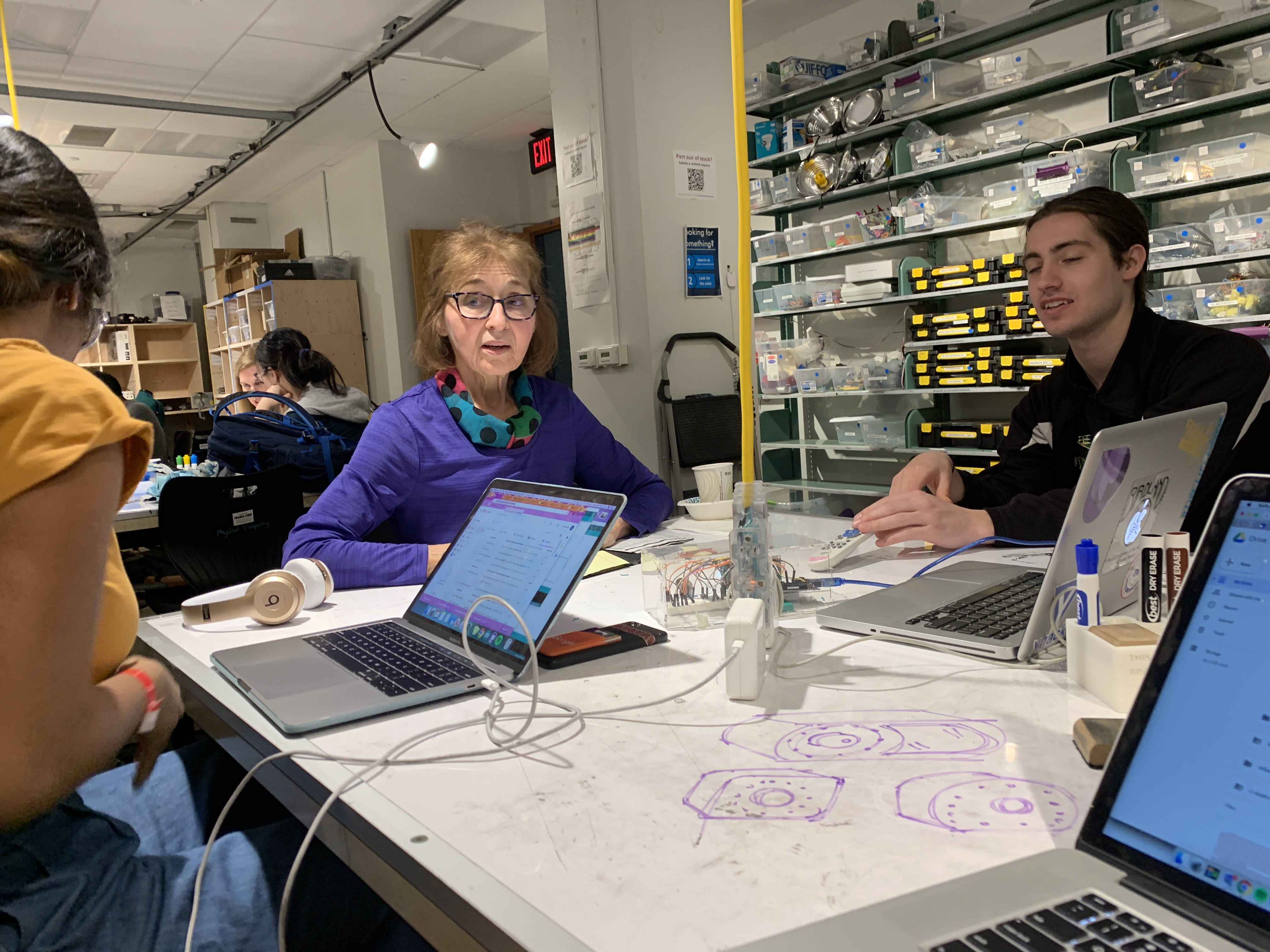
Talking with Lois during the first prototype critique to determine more specifically what her needs were (more info can be found on that previous documentation)
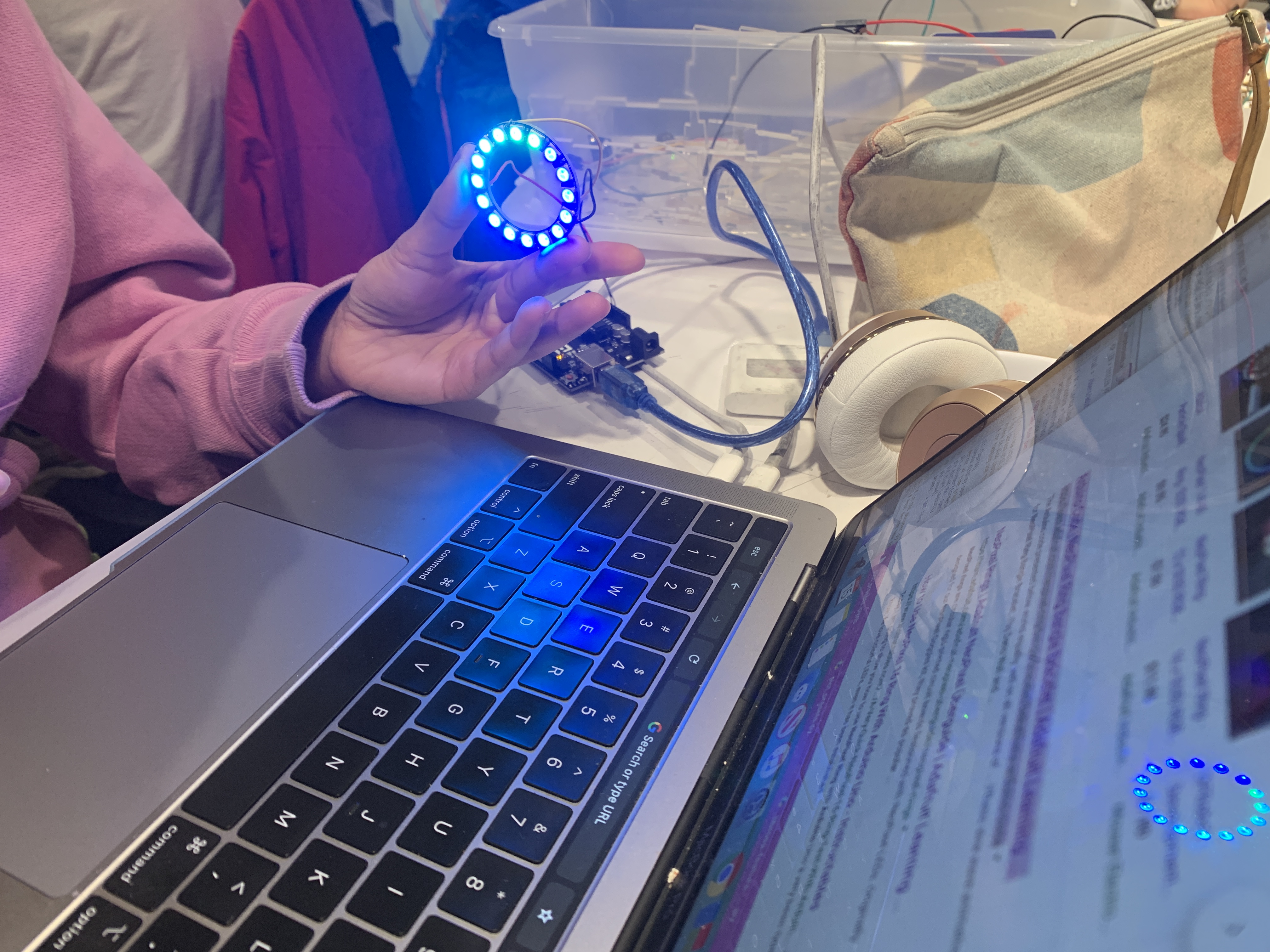
Working with the smaller NeoPixel and seeing the different effects it could have in the library (Look at the reflection on the laptop screen, pretty cool!)
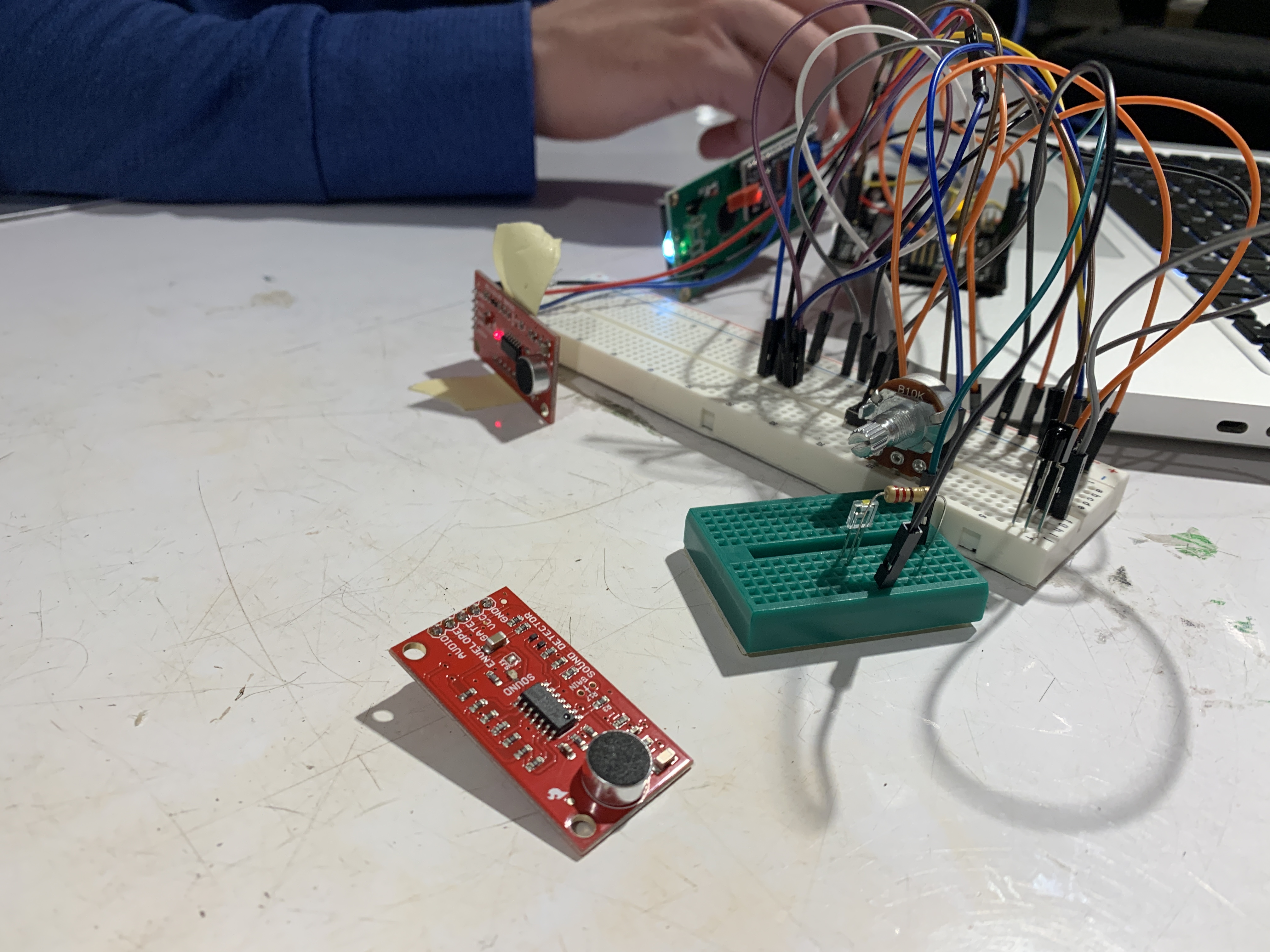
At this point we had a lot of difficulty with the sound sensor we were given so after talking to Zach we changed it to the RobotDyn sound sensor
We began to work on the final physical model for Lois. We worked with understanding the dimensions of what we wanted our final product to be and how we wanted it to roughly look. Using the dimensions of the sensors and Neopixel that we already had, we created a cardboard representation of what the interactions associated with the device could be.
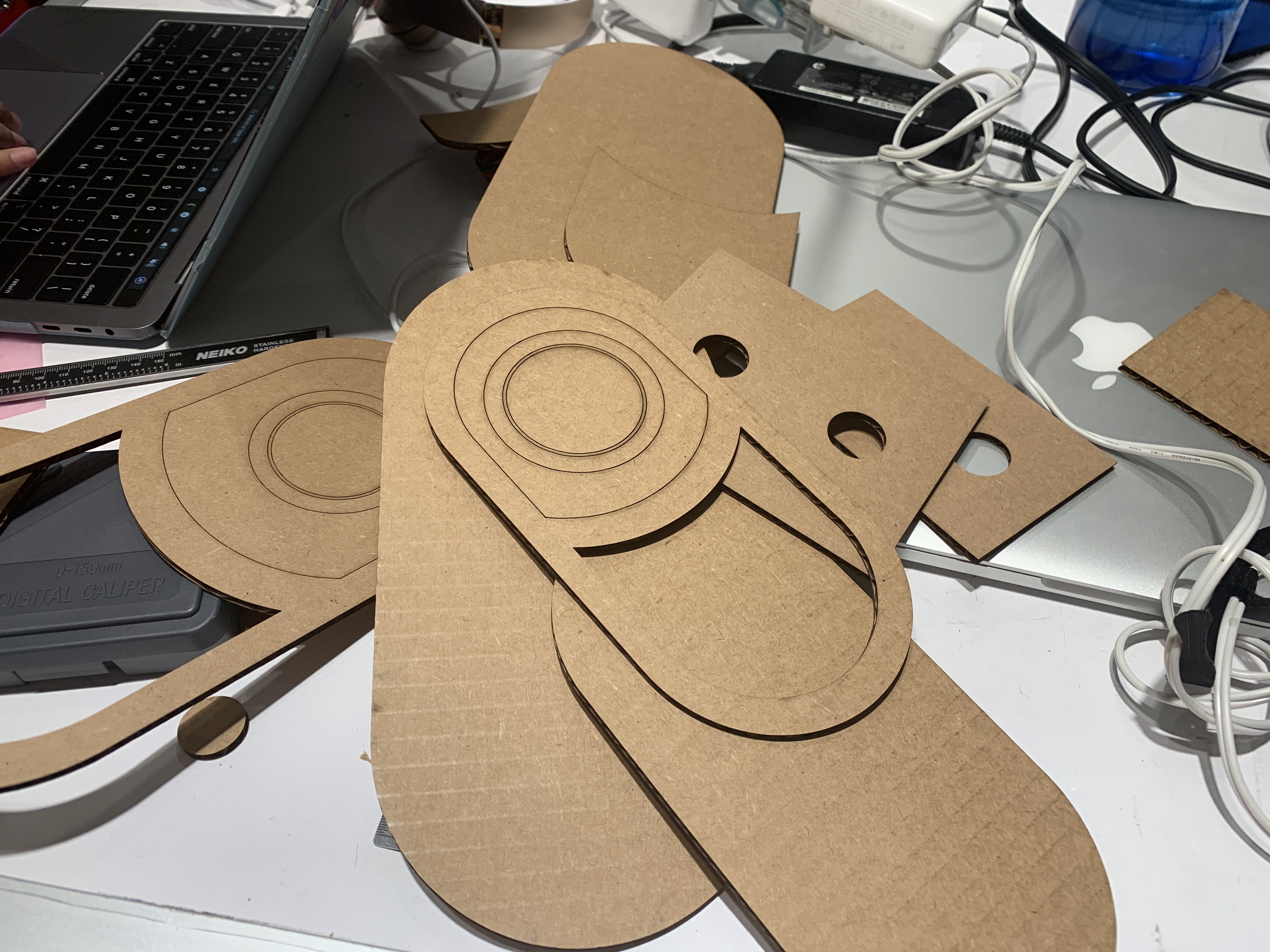
Lasercut cardboard templates to figure out dimensions of final product
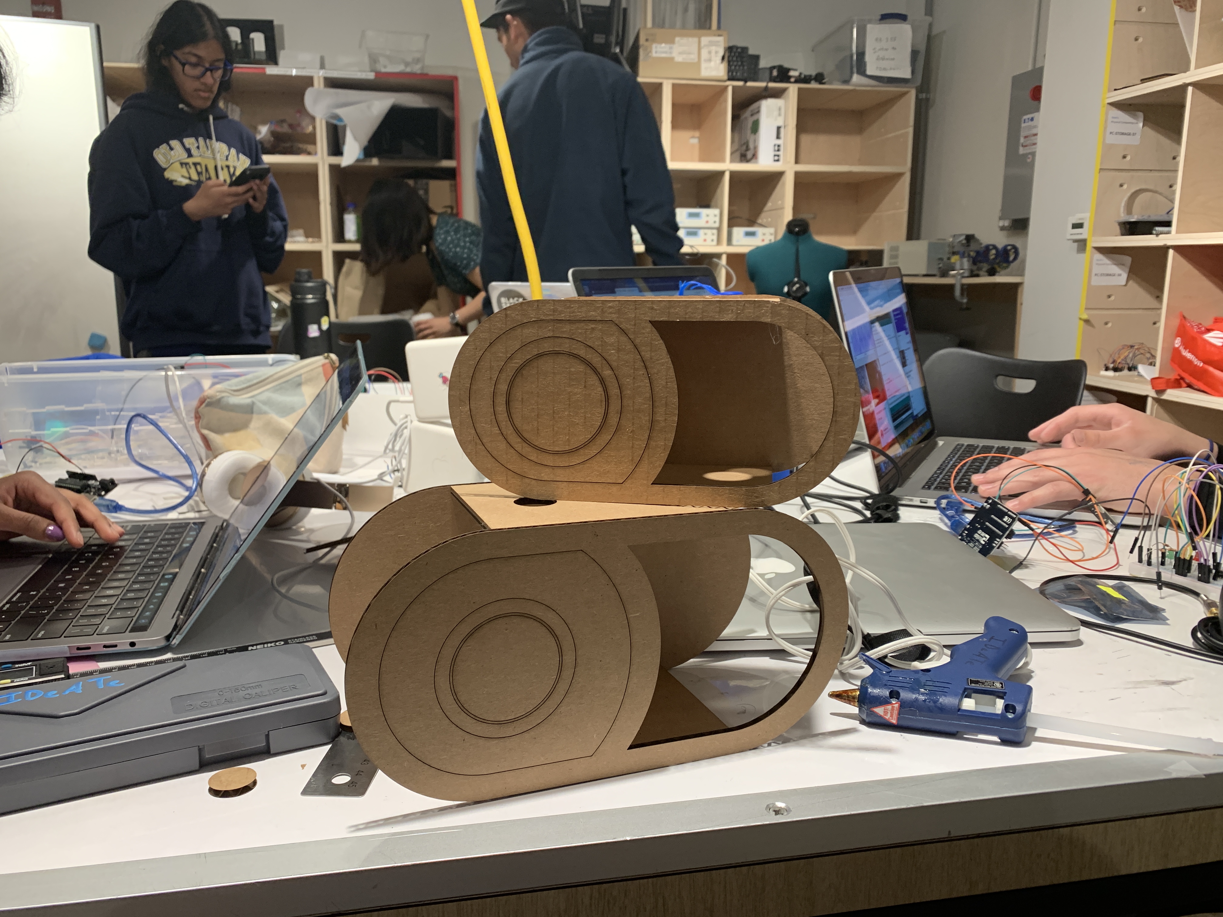
After looking at the two cardboard mockups, we decided to work with the smaller model size—determining it was easier to print as well as more fitting in Lois’ den
After understanding dimensions we began to CAD out the final device.
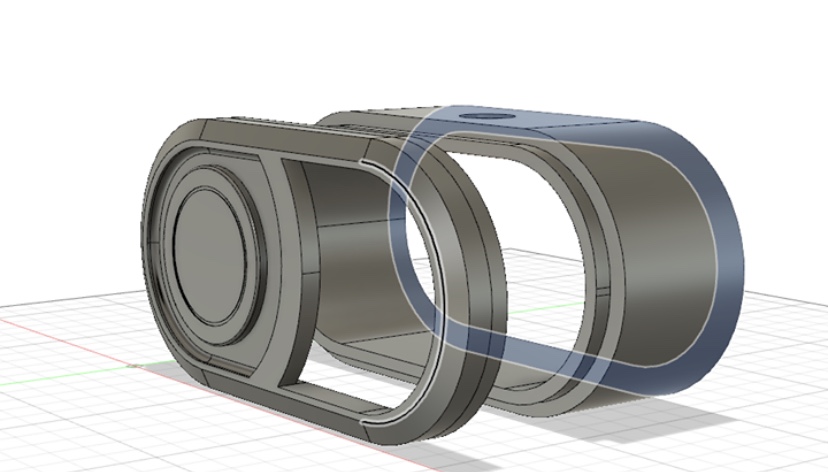
Designing the final device on Fusion360 (2/3 parts are shown)
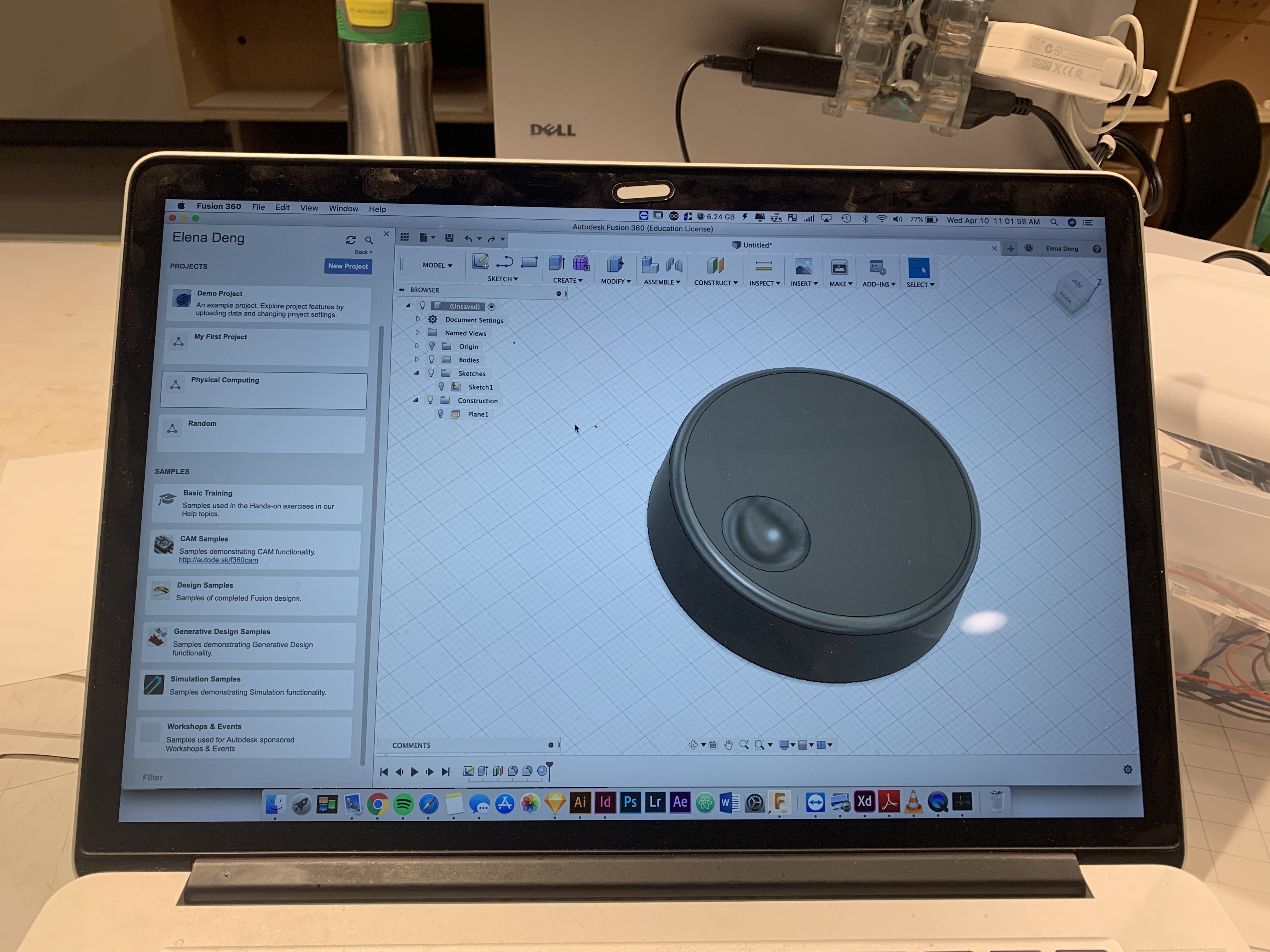
Designing the knob on Fusion 360
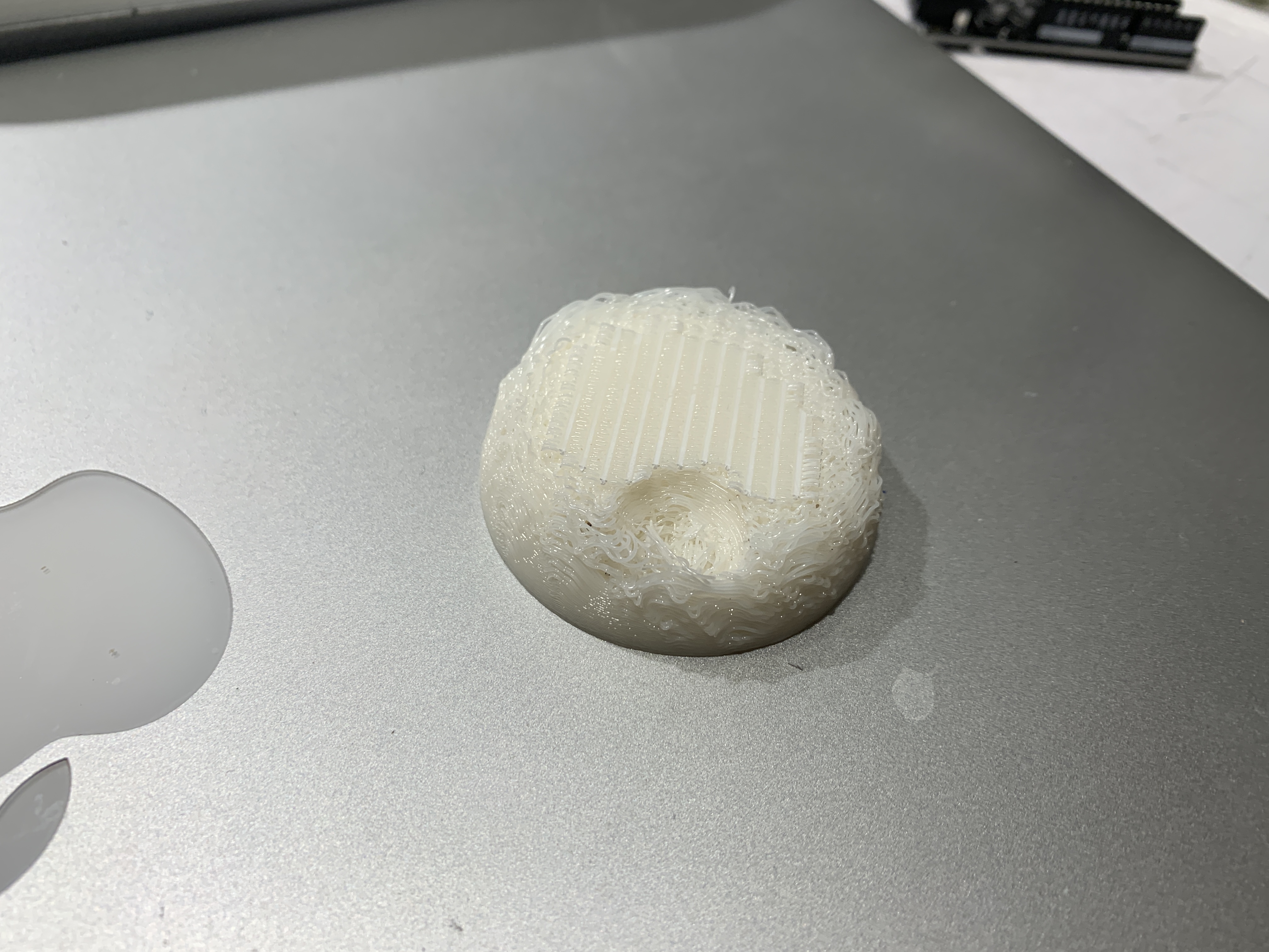
Failed 3D printed knob (the supports didn’t work on the Stratasys?)
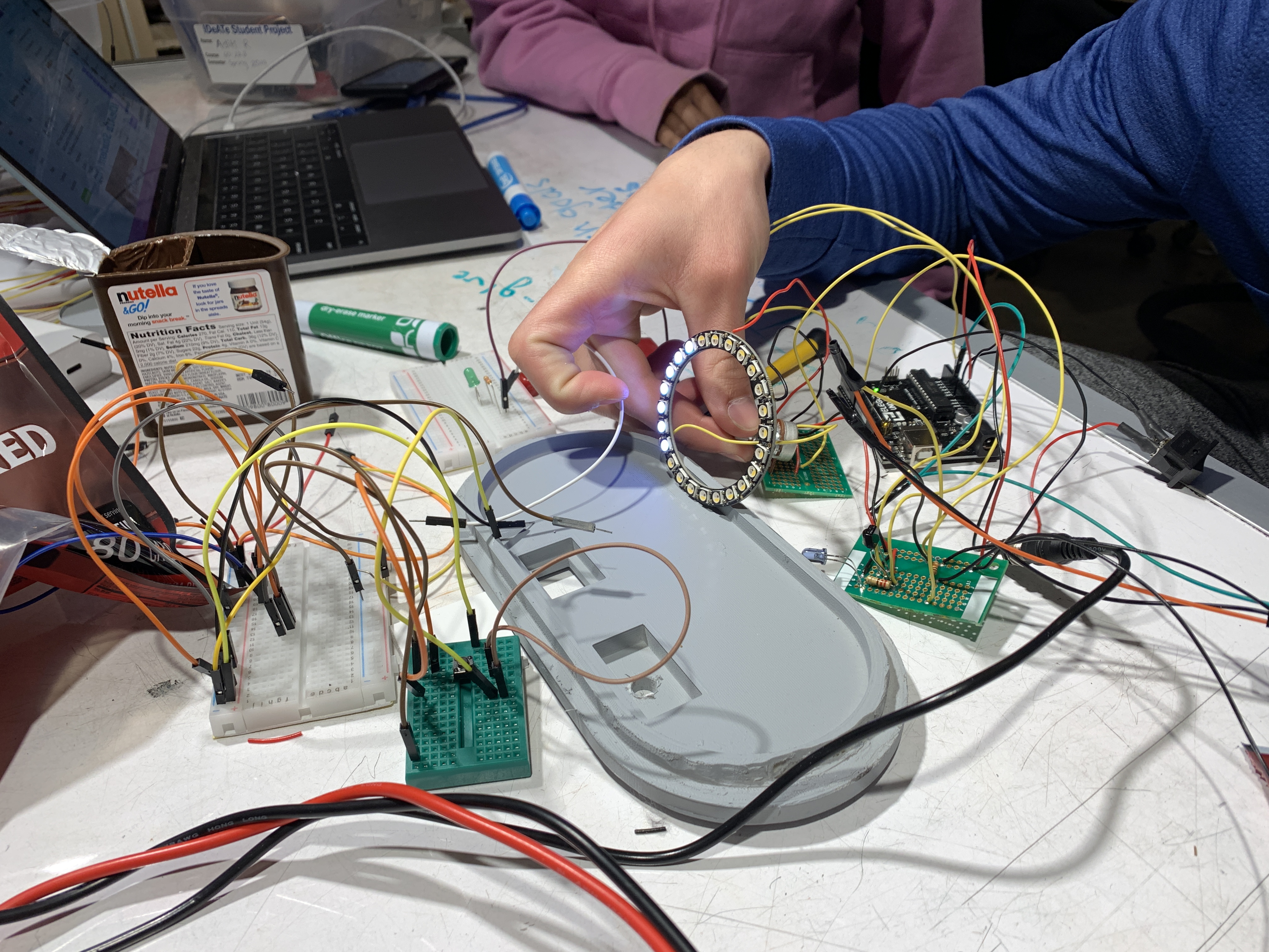
We got the first and third print done, and as the second print was on the queue we explored the way that the sensors fit as well as the way that the NeoPixel shined through the PLA.
Working with the NeoPixel and figuring out the optimal placement for it within the device
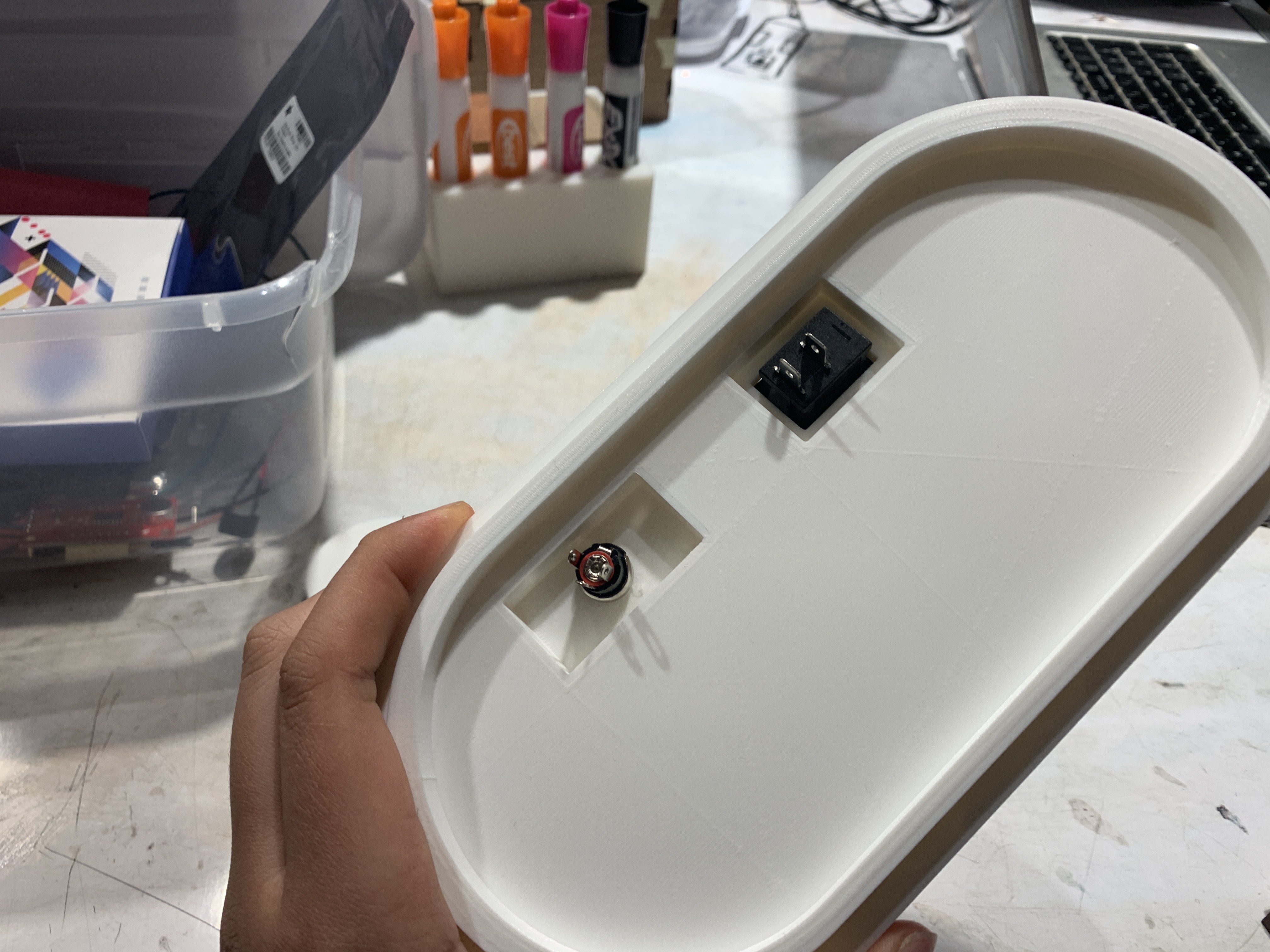
Testing the fit of the rocker switch and 5v input
After all three pieces were printed, we realized that somewhere along the process of creating the 3D print, the joints where the pieces were meant to be connected did not connect properly. We had to dremel the joints down carefully; however, because the joints were hidden, it would not affect the overall craft.

Dremeling the parts to allow the pieces to fit together (dremeling Elena’s last brain cell away)
We decided to bondo the pieces of the 3D print that did not turn out smooth and because bondo has a color, we needed to spray paint two of the pieces. Due to availability of spray paint we only had gray. After sanding down some rough edges, we added bondene to fragile parts of the print. We were now ready to add the electrical components into the device.
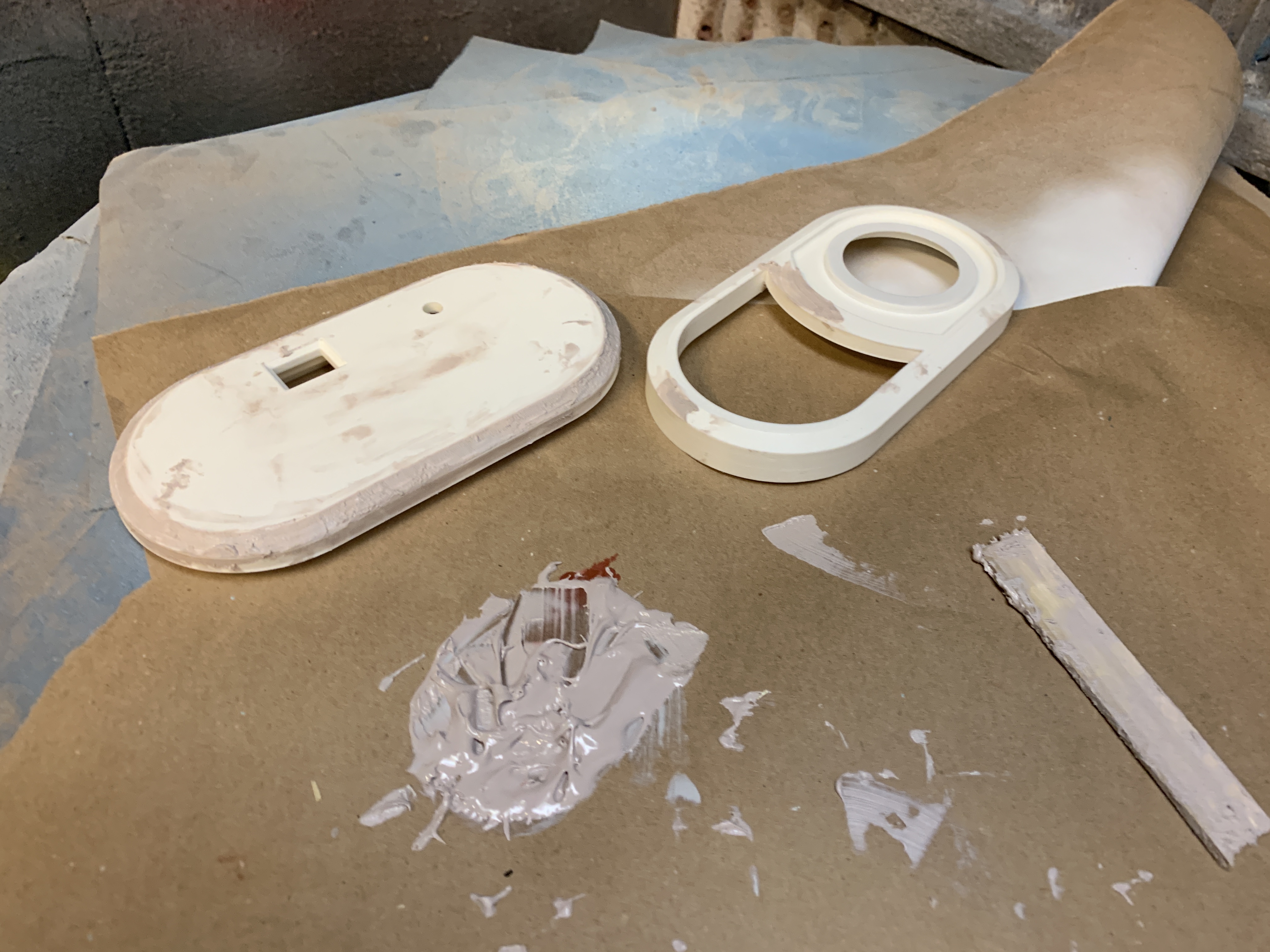
Bondo to smooth out rough parts of the print
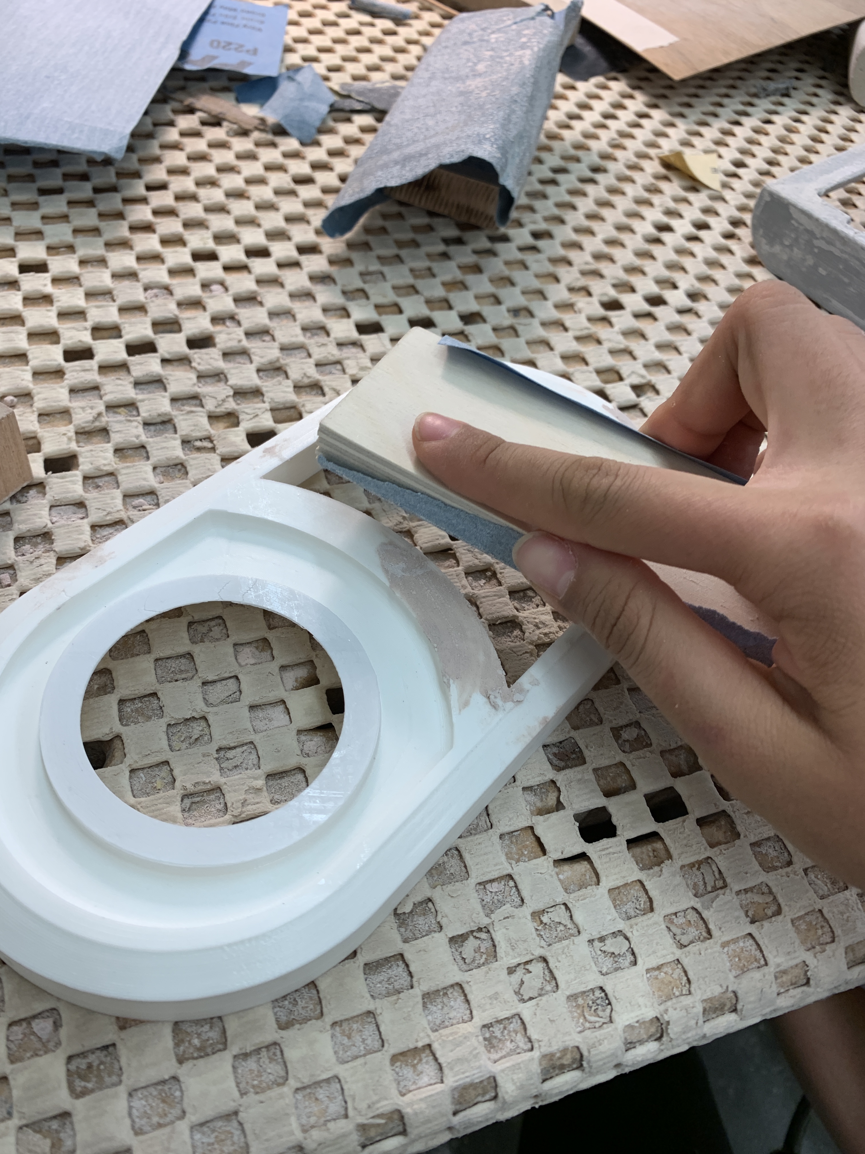
Sanding down the bondo to make the edges and print smoother
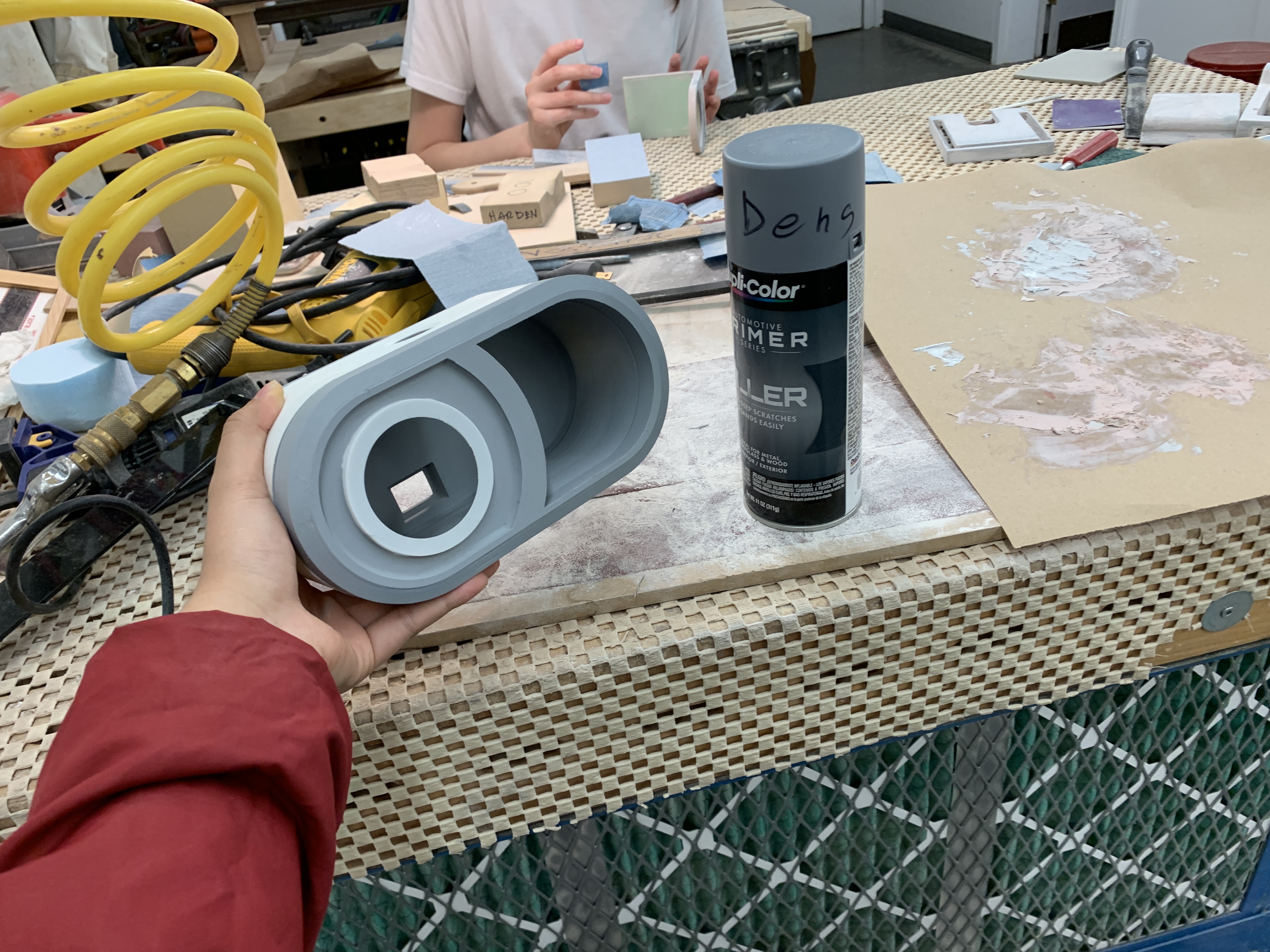
Spray painted part
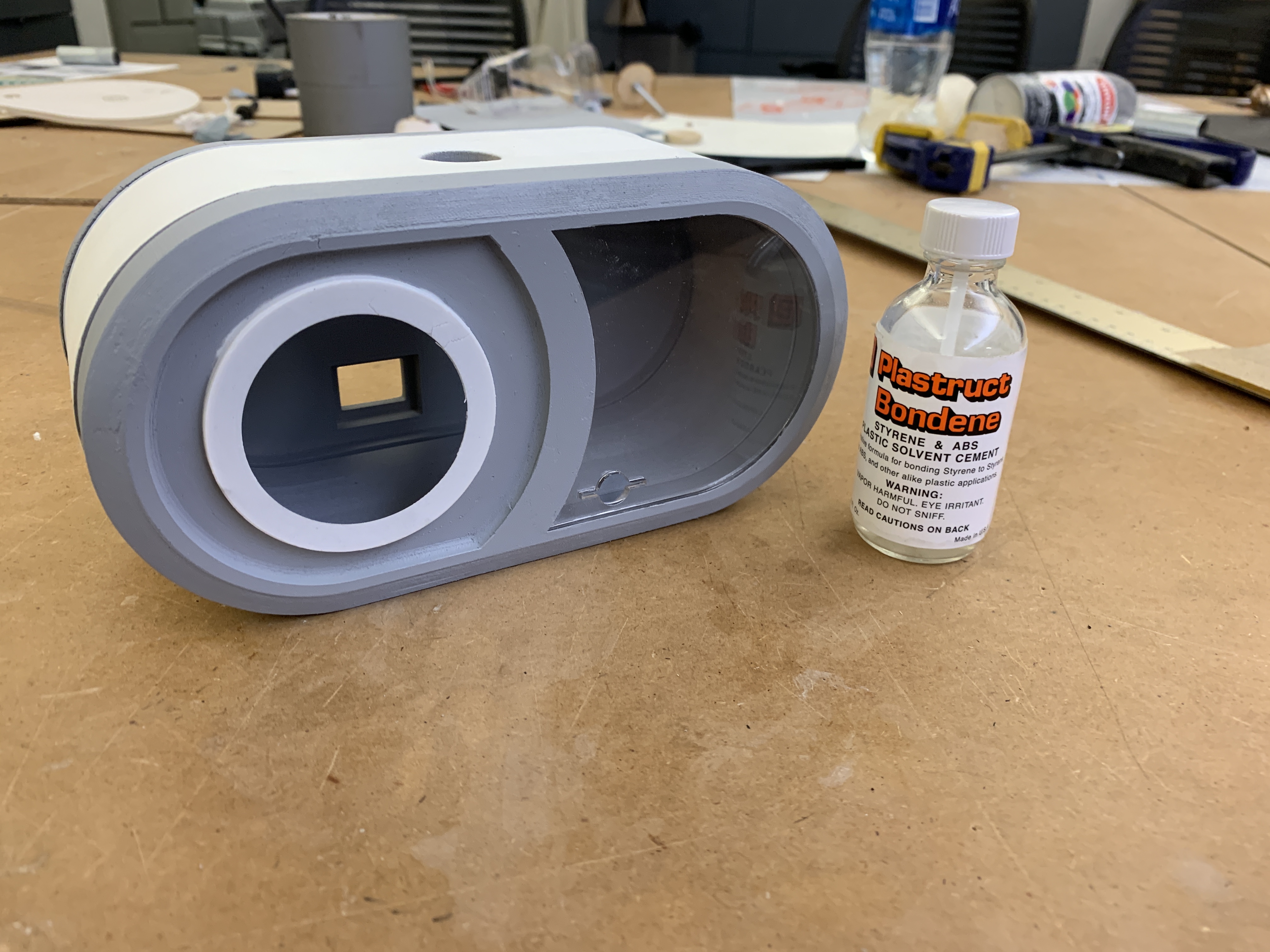
Bondene’d the weaker parts of the print (especially the NeoPixel print area to ensure that the part would not crack
As the physical model was being made, we worked on the Neopixel functionality as well as the sound sensor detection.
Working with the Neopixel and combining it with the code for the sound detector
Even after switching the sound sensor, when the sensor picked up on any sound, the reading would spike, which meant that if someone made a loud noise on the television program, the volume would automatically be lowered. We didn’t want this to happen so after talking to Zach, we realized that we could average out the sound readings for a period of time and that way if the sound was continuously loud for about two-three seconds, the television volume will be lowered.
After figuring out the code we began to work through the wiring diagram and soldering the pieces onto the Arduino.
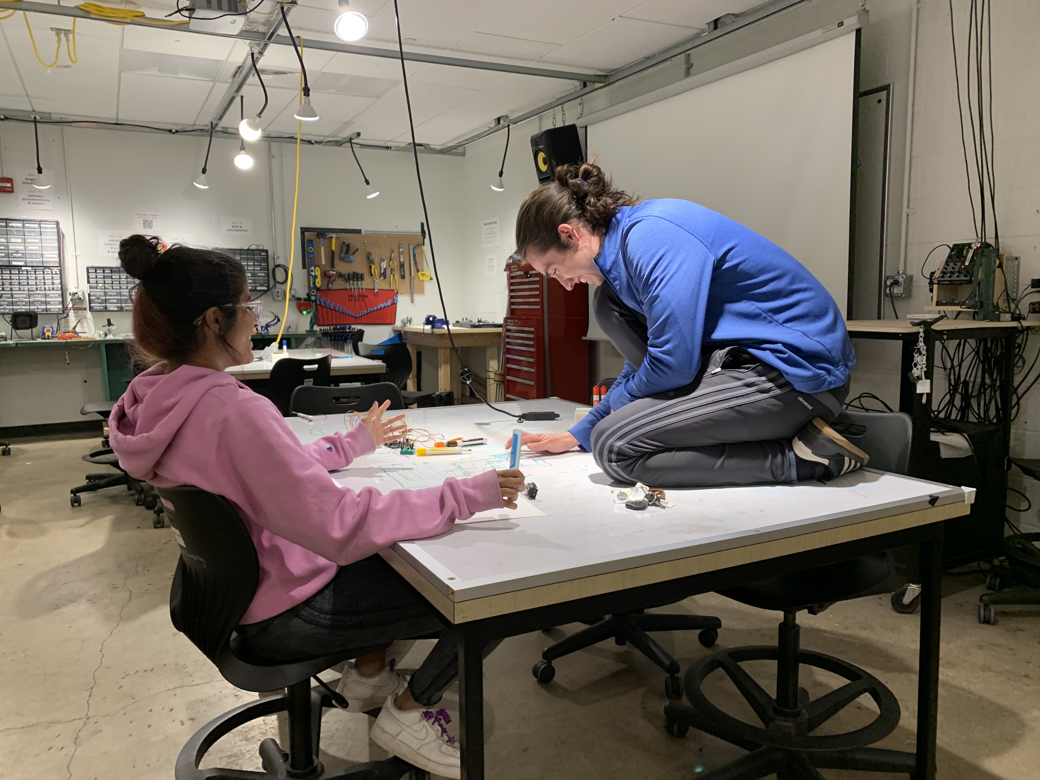
Collaborative circuitry diagram creation!
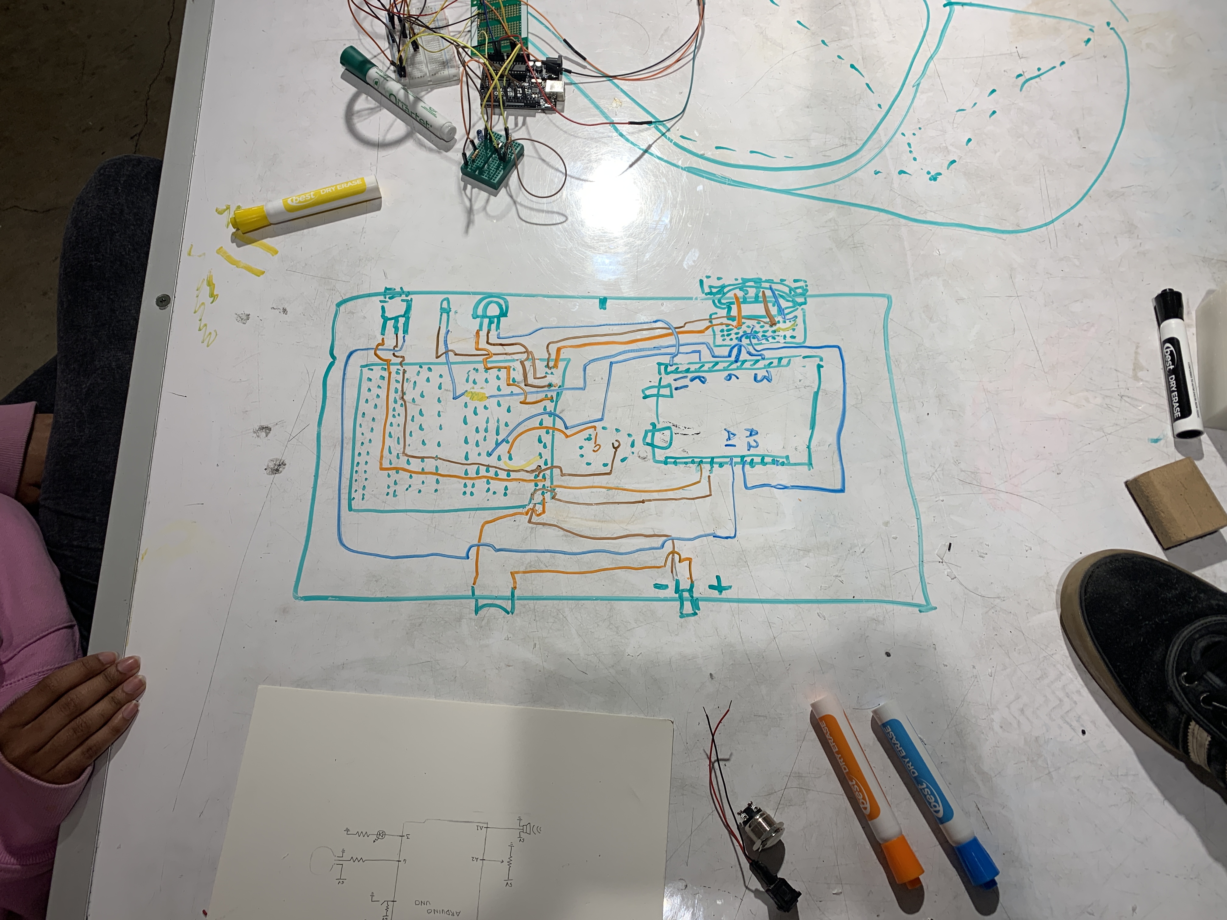
Final Circuitry Diagram drawn on white board
As we began to house the electronics in the device, we had some difficulty with the potentiometer placement so that the knob would spin on an axis. Therefore, we had to create a second level of sorts within the device using a separate breadboard from the one where the IR sensors were located.
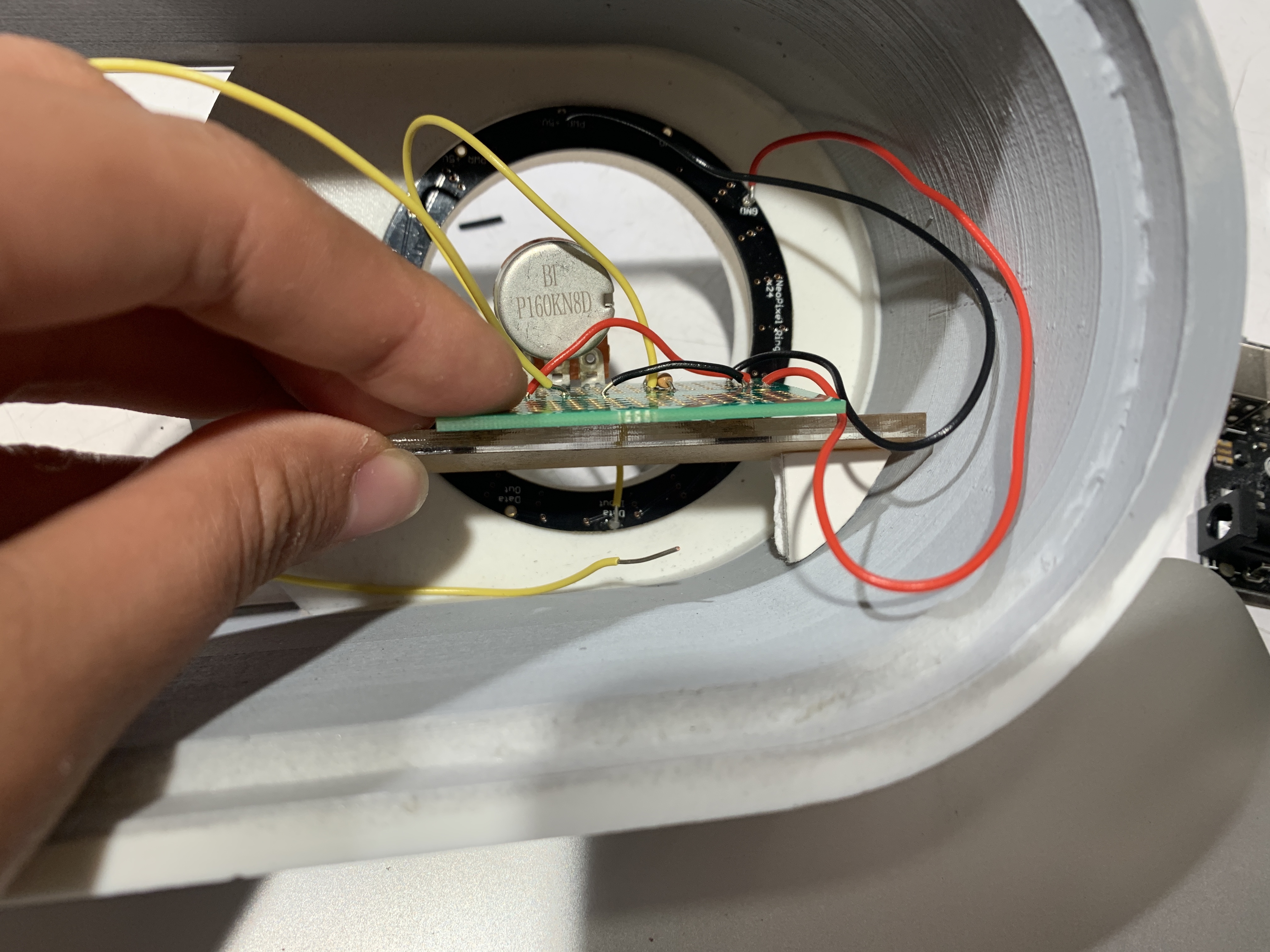
Creating a second level to hold the breadboard for the potentiometer in place
Final placement of internal components
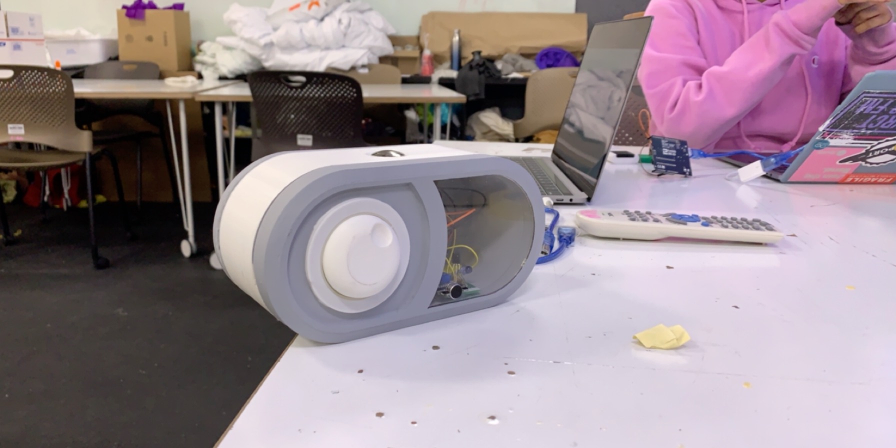
Finished product before critique with electronics within the housing after testing with the projector.
After the final prototype was assembled, we tested out functionality with the projector volume and simulated the television volume with our voice. Then it was on to the final critique!
Conclusion and lessons learned
We received a lot of comments to the effect of “could add more control on this box.” Some people suggested having other dials to control the commercial timer. At the moment, it is permanently set to 30 seconds, but some programs have commercials that are a minute long or more. In addition, people suggested making a dial that changes how much the volume is decreased. Both of these dials would be easily implemented in the Arduino code. However, they would have required a good amount of more testing. In the future these could be a possibility.
On the other hand, the vast majority of our comments praised our “clean fabrication,” but a few comments brought attention to our acrylic window saying, “clear window looks a bit unpolished.” The functionality of the acrylic was to make sure that the infrared LED would transmit the cleanest signal to the TV, however, by doing so we exposed the inner wires and electronics. I do believe we could make a future design that makes sure the electronics are not as visible. In particular, most remotes have a nice form around their infrared LED that seems to direct the signal better. Perhaps we would benefit from implementing a housing for the LED that imitates that shape.
Other comments involved the fact that the box had to face the TV and that the “Red vs. green lights confuse me.” However, these decisions were made under Lois’ direction. The way she sits as she watches TV makes it so that it is okay for the box to face the TV. In addition, she made it clear that she would like the volume-down phase to flash green and the volume-up to flash red.
All in all, there were few things that Lois insisted on. A challenge we faced was that after our first meeting with Lois we did not have a clear direction or path.
In the future, we would have a more impactful interview, especially if we emphasized to her that we would like specific ideas. What we should have noticed in the first interview was just how interested Lois was in finding a solution to her TV loudness. It was surprising how excited and pleased Lois was at every step of the way in our prototypes. After our final critique, she brought up the idea of marketing our product, which was a bit of a foreign idea for us However, we felt is was one of the many benefits of working with an older person because their perspective is much broader and more experienced than ours. It was truly a pleasure to work with her.
Technical Details
Schematic
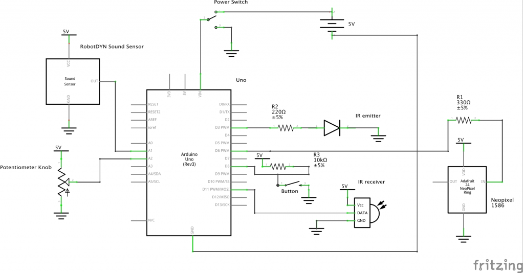
Schematic for TV volume regulator
Code
/*
 * TV Volume Regulator
 * Elena Deng, Connor Maggio, Aditi Raghavan
 *
 * Device Functionality:
 * If the volume coming from the TV is too loud,
 * the device sends an IR remote codes to the TV to
 * turn down the volume. After 30 seconds the
 * device sends IR codes to turn the volume back up.
 * A momentary pushbutton can also be used to turn the
 * volume up or down.
 *
 * Required Components: Arduino Uno, Potentiometer, IR LED,
 * IR receiver, Momentary Push Button, Toggle Switch,
 * Power Source, Audio Sensor (RobotDYN Sound Sensor),
 * 24 LED Neopixel, 5V Power Source
 *
 * Inputs: Button, Sound Sensor, Potentiometer
 * Outputs: IR signals, Neopixel
 *
 * PINS:
 * PIN 3 - IR LED
 * PIN 6 - Neopixel
 * PIN 8 - Momentary Button
 * PIN 11 - IR Receiver
 * PIN A1 - Sound sensor
 * PIN A2 - Potentiometer
 *
 * Notes:
 * 1. Neopixel library requires that Pin 6 is used.
 * 2. The IR libaries require the IRLED to be pin 3
 * 3. IR Codes are specific to one TV and should be changed
 * accordingly
 * 4. Connect 5V power source to Vin on the Arduino Uno
 *
 */

#include <ir_Lego_PF_BitStreamEncoder.h>
#include <boarddefs.h>
#include <IRremoteInt.h>
#include <IRremote.h>
#include <Wire.h>
#include <Adafruit_NeoPixel.h>
#define LED_PIN     6

// LED on the Neopixel
#define LED_COUNT  24

// NeoPixel brightness
#define BRIGHTNESS 50

// Declare our NeoPixel strip object:
Adafruit_NeoPixel strip(LED_COUNT, LED_PIN, NEO_GRBW + NEO_KHZ800);

// Declaring pins
const int BUTTON = 8;
const int AUDIOPIN = A1;
const int POTPIN = A2;
const int IR_TX = 3;
const int IR_RECV = 11;\

// Declaring thresholds
int ledThresh;
int oldLedThresh;
int potVal;
int audioThresh;
int threshold;

// Setting up ir receiver and sender
IRrecv irrecv(IR_RECV);
IRsend irsend;
decode_results results;

// Averaging
int dB_samples[200];
int count = 0;
int current_dB;
unsigned long sum = 0;
unsigned long average;

bool remoteButtonPressed;
bool turnVolumeDown = false;

//Detecting Audio
bool peakWait = true;
bool nonPeakWait = false;
unsigned long peakTimer;
unsigned long belowThres = 2000;
unsigned long nonPeakTimer;
unsigned long aboveThres = 0;

//Button
int buttonState = HIGH;
int oldButtonState = HIGH;
bool buttonPressed;

//Commercial data
unsigned long cmlStart;
unsigned long cmlTimer;

//IR Values
String remoteButton = "1897e817";
int muteButton;
int unmuteButton;

// FSM States
const int MODE_LISTEN = 0;
const int MODE_MUTE = 1;
int currentMode = MODE_LISTEN;

struct TV{
  int  volThreshold = 100;
  bool isMute = 0;
} LoisTV;

void setup() {
  pinMode(BUTTON, INPUT_PULLUP);
  pinMode(AUDIOPIN, INPUT);
  pinMode(POTPIN, INPUT_PULLUP);
  pinMode(IR_RECV, INPUT);
  pinMode(IR_TX, OUTPUT);
  Serial.begin(9600);
  irrecv.enableIRIn();
  irrecv.blink13(true);
  strip.begin();
  strip.show();
  strip.setBrightness(50);
}

void loop() {
  /*
   * Potentiometer Threshold meter
   */
  potVal = analogRead(POTPIN);
  audioThresh = map(potVal, 0, 1023, 0, 500);
  int temp = map(potVal, 0, 1023, 0, 48);
  ledThresh = map(temp, 0, 48, 0, 24);
  if (ledThresh != oldLedThresh){
    ledPotentiometer(ledThresh);
    oldLedThresh = ledThresh;
  }
  LoisTV.volThreshold = audioThresh;

  /*
   * Averaging
   */
  current_dB = analogRead(AUDIOPIN);
  sum = sum + current_dB;
  sum = sum - dB_samples[count];
  dB_samples[count] = current_dB;
  count = (count+1) % 200;
  int average = sum/200;

  /*
   * Button
   */
   buttonState = digitalRead(BUTTON);
   if (!buttonState && oldButtonState) buttonPressed = true;
   oldButtonState = buttonState;

  /*
   * Detecting Loudness
   */
  if ((average >= LoisTV.volThreshold) && peakWait) {
    peakTimer = millis();
    nonPeakWait = true;
    peakWait = false;
    belowThres = millis() - nonPeakTimer;
  }
  if ((average < LoisTV.volThreshold) && nonPeakWait) {
    nonPeakTimer = millis();
    peakWait = true;
    nonPeakWait = false;
    aboveThres = millis() - peakTimer;
  }


  /*
   * Mode Management and Functionality
   */
  switch(currentMode)
  {
    case MODE_LISTEN:
      if ((aboveThres >= 1000)
          || ((aboveThres >= 200) && (belowThres < 400))) {
        turnVolumeDown = true;
      }
      /*If above threshold or the button is pressed
       when in listening mode, send turn volume down codes
      */
      if (turnVolumeDown || buttonPressed)
      {
        cmlStart = millis();
        pulseGreen(5);
        irsend.sendNEC(0x1897926D, 32); // projector Volume Down
        delay(100);
        irsend.sendNEC(0x1897926D, 32); // projector Volume Down
        delay(100);
        irsend.sendNEC(0x1897926D, 32); // projector Volume Down
        delay(100);
        irsend.sendNEC(0x1897926D, 32); // projector Volume Down
        delay(100);
        irsend.sendNEC(0x1897926D, 32); // projector Volume Down
        delay(100);
        irsend.sendNEC(0x1897926D, 32); // projector Volume Down
        delay(100);
        irsend.sendNEC(0x1897926D, 32); // projector Volume Down
        delay(100);
        irsend.sendNEC(0x1897926D, 32); // projector Volume Down
        delay(100);
        LoisTV.isMute = true;
        buttonPressed = false;
        currentMode = MODE_MUTE;
      }
      break;
    case MODE_MUTE:
      cmlTimer = millis() - cmlStart;
      /* Decodes results from the TV remote to see if certain button
       *  is being pressed.
       */
      if (irrecv.decode(&results)) {
        Serial.println("sent");
        Serial.println(String(results.value, HEX));
        Serial.println(String(results.value, HEX));
        Serial.println(String(results.value, HEX));
        if (String(results.value, HEX) == remoteButton) {
          remoteButtonPressed = true;
        }
        irrecv.resume();
      }

      /* If the button is pressed or the center button on the TV remote is pressed
       *  or the timer has elapsed 3000 seconds, the device sends codes to turn
       *  the volume back up on the TV
       */
      if (buttonPressed || remoteButtonPressed || (cmlTimer >= 30000))
      {
        pulseRed(5);
        irsend.sendNEC(0x189712ED, 32); // projector Volume Up
        delay(40);
        irsend.sendNEC(0x189712ED, 32); // projector Volume Up
        delay(40);
        irsend.sendNEC(0x189712ED, 32); // projector Volume Up
        delay(40);
        irsend.sendNEC(0x189712ED, 32); // projector Volume Up
        delay(40);
        irsend.sendNEC(0x189712ED, 32); // projector Volume Up
        delay(40);
        irsend.sendNEC(0x189712ED, 32); // projector Volume Up
        delay(40);
        irsend.sendNEC(0x189712ED, 32); // projector Volume Up
        delay(40);
        irsend.sendNEC(0x189712ED, 32); // projector Volume Up
        delay(40);
        LoisTV.isMute = false;
        buttonPressed = false;
        aboveThres = 0;
        belowThres = 2000;
        turnVolumeDown = false;
        currentMode = MODE_LISTEN;
      }
      break;
  }
}

// Pulses Neopixel Red
void pulseRed(uint8_t wait) {
  for (int j = 0; j < 256; j++) { // Ramp up from 0 to 255
    // Fill entire strip with white at gamma-corrected brightness level 'j':
    strip.fill(strip.Color(strip.gamma8(j), 0, 0, 0));
    strip.show();
    delay(wait);
  }

  for (int j = 255; j >= 0; j--) { // Ramp down from 255 to 0
    strip.fill(strip.Color(strip.gamma8(j), 0, 0, 0));
    strip.show();
    delay(wait);
  }
}

// Pulses Neopixel Green
void pulseGreen(uint8_t wait) {
  for (int j = 0; j < 256; j++) { // Ramp up from 0 to 255
    // Fill entire strip with white at gamma-corrected brightness level 'j':
    strip.fill(strip.Color(0, strip.gamma8(j), 0, 0));
    strip.show();
    delay(wait);
  }

  for (int j = 255; j >= 0; j--) { // Ramp down from 255 to 0
    strip.fill(strip.Color(0, strip.gamma8(j), 0, 0));
    strip.show();
    delay(wait);
  }
}

// Maps potentiometer values to Neopixel LED's
void ledPotentiometer(uint8_t numLed){
  for (int i = 0; i < 24; i++) {
    if (i < numLed+1) { //the +1 keeps one LED on at all times
      strip.setPixelColor(i, 180, 180, 180); // turn on this LED, also adjusts colors                                                                                                                                                                                                                                                                                                                                                                                                                                                                                                       ); //turn on this LED, adjust values to affect colors and brightness of LEDs

    }
    else {
     strip.setPixelColor(i, 0, 0, 0); //turn off this LED

    }
    strip.show();
  }

}
Comments are closed.