
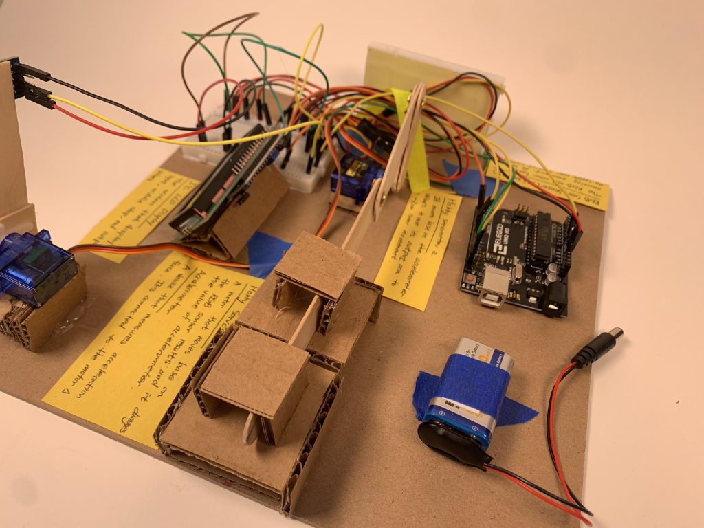
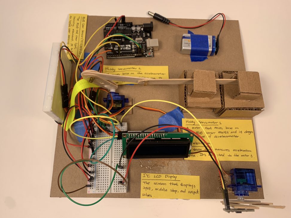
Top view of the entire double transducer
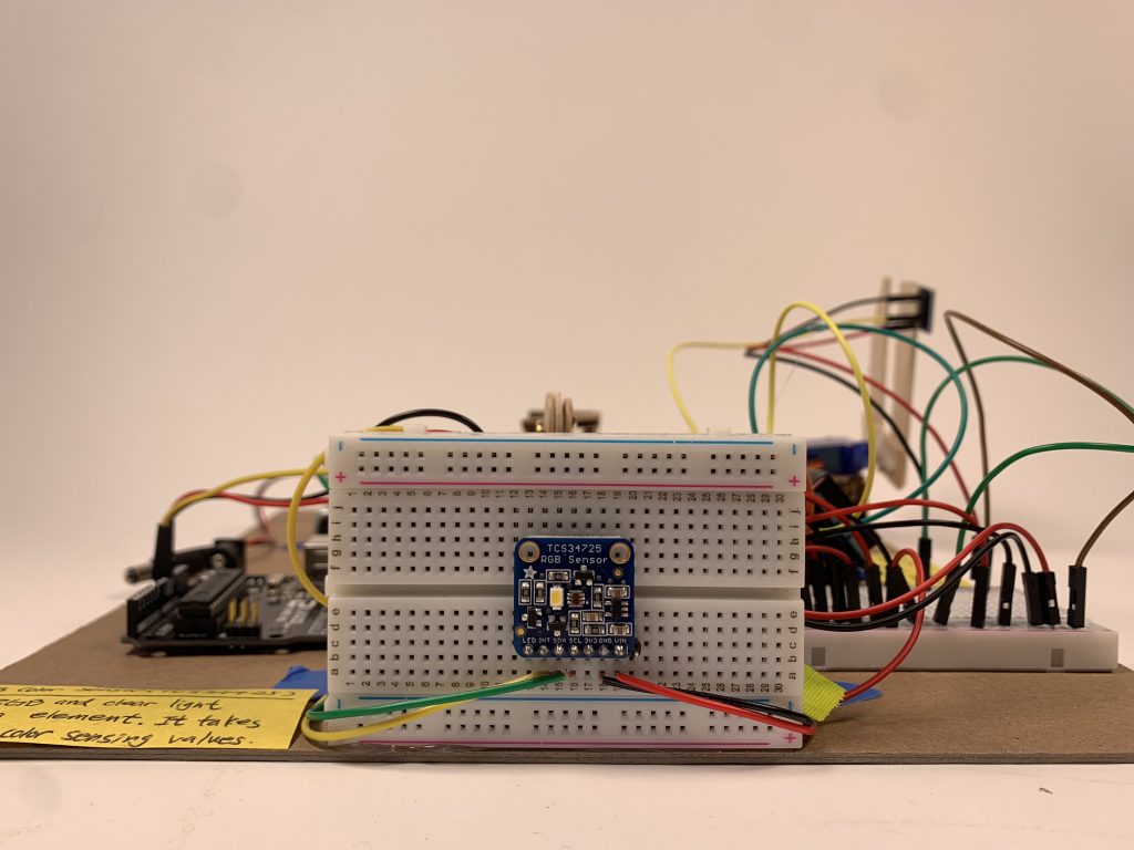
Input: Adafruit TCS34725 Color Sensor
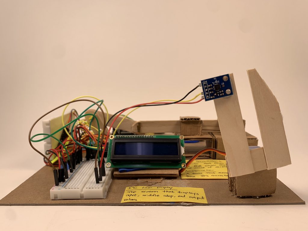
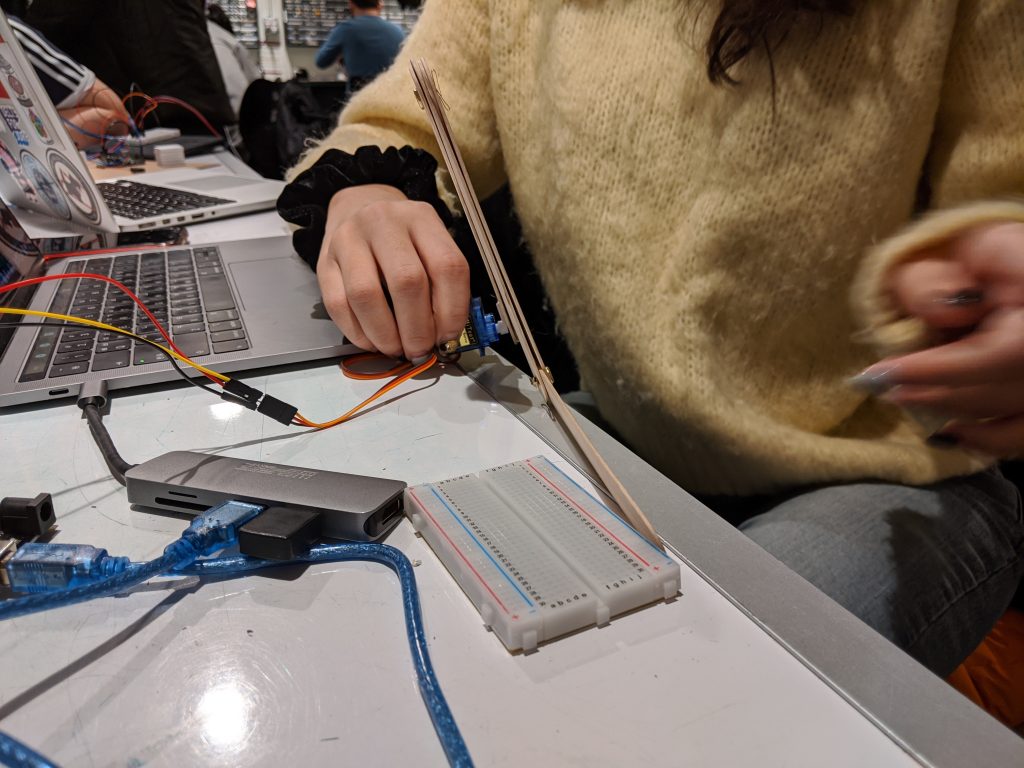
Middle Step: ADXL335 Accelerometer on a popsicle stick structure attached to a servo motor
Output: an popsicle arm that moves forward when the servo motor rotates
Description
This double transducer reads a color sensor on the left side and converts the result into corresponding rotational movements of a motor which is connected to an accelerometer with popsicle sticks structure. The movements of the accelerometer result in the linear movement of a popsicle stick. The closer the color is to red, the less linear movements the popsicle structure makes.
Discussion
The most important part of this project was in communication with other teams. To make our double transducer work transducer to transducer, we did some experiments by setting each sensor results to specific values in an Arduino. For an input color sensor specifically, we used different colors of objects to give different signals to a color sensor. While it worked internally, because we are getting input from the previous team’s output, we needed to communicate with other teams and test our model to theirs. Since we were the last team, we met up with the previous team and tested our color sensor. Throughout this process, we learned communication not only within a team but also among multiple working units is critical especially in a big project.
One of the challenging parts was the final ‘linear’ movement. We first started off with popsicle sticks with their original length to see how it works; however, it, first, makes circular movements, and, second, moved too much which was not appropriate to the given board size. We did some experiments to find proper lengths of popsicle sticks corresponding to the board size, and found out shorter popsicle sticks make smoother and more gradual movements. However, it still did not make a perfectly linear movement, so we built cardboard houses that fasten a popsicle stick. Before building the linear movement structure, we calculated the lengths and degrees, but it unexpectedly did not turn out that way. Throughout the multiple problem-solving processes we ended up having the model we wanted, which was different from what we first designed. We realized there always can be differences between calculations and the actual executions.
As for the middle part, we originally decided to use a joystick and popsicles to move the joystick. However, we found out that the joystick tends to latch on to the middle or the two ends, and it is very hard to make it stay in the middle. With a backup plan during our idea session, we made the motor rotates an accelerometer instead, which turned out to be successful. We learned that we should always consider alternatives in case our plan fails, and if something doesn’t work, we should not dwell on it but should look for different solutions.
Process Images
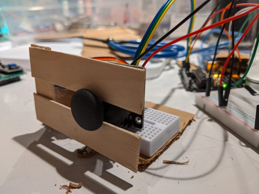
Originally we planned to use a joystick for our middle step, but we had difficulties making it stay in the middle, so we switched to an accelerometer instead.
Planning the mechanism for converting motor rotation into linear movement. We realized a popsicle stick attached to the motor is too long.
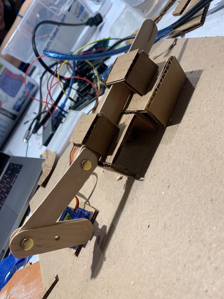
Near-finished product for our output. We decided to make cardboard “houses” to hold the popsicle stick in place.
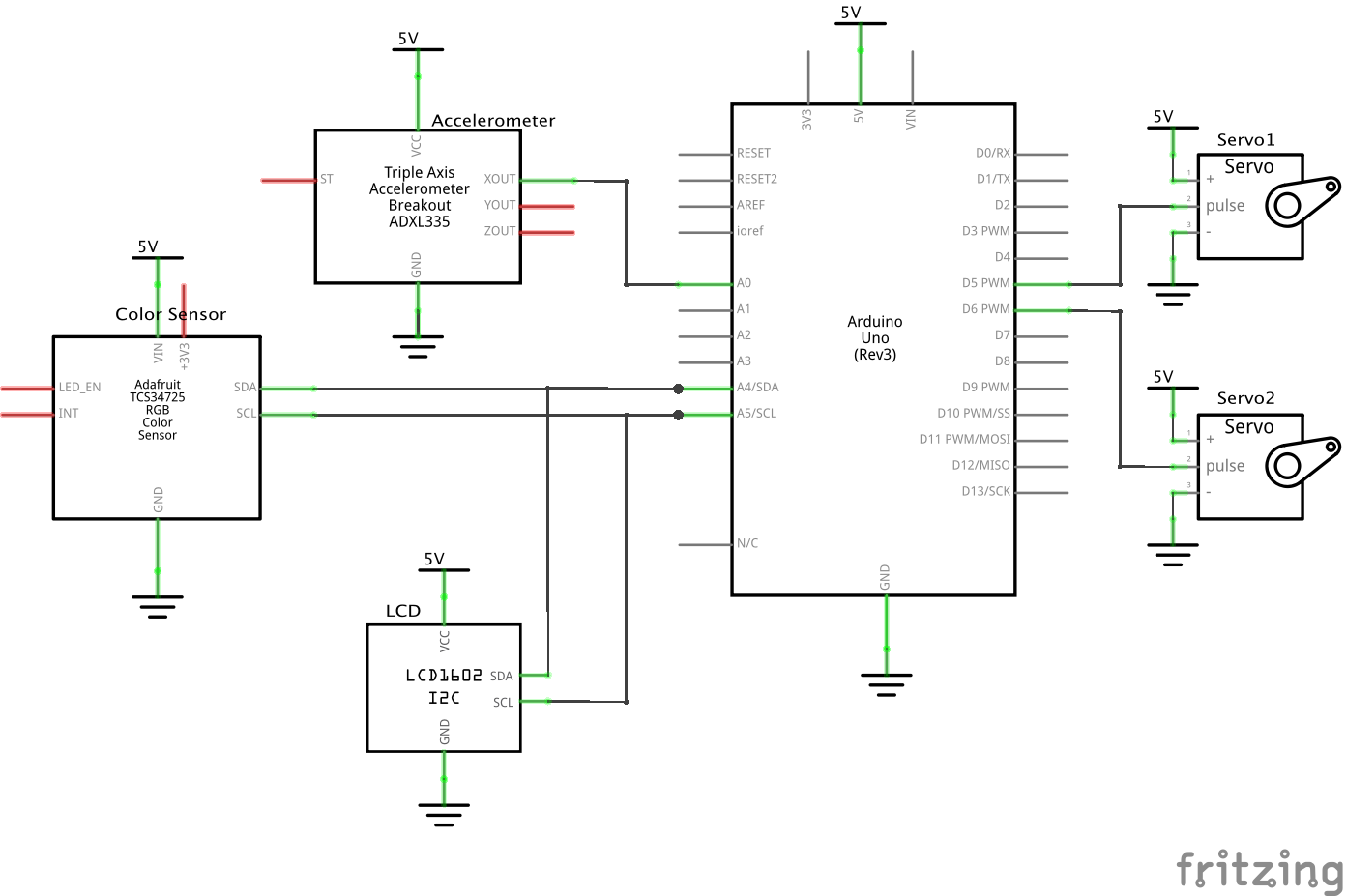
Schematic
Code Submission
/*
 * Project 1: A Double Transducer - Color to Linear Position
 * Alan Zhu and Yun Lee
 *
 * Description: the code here first takes the rgb input from the
 * color sensor and map it to a single value (hue), and uses that
 * value to determine the degree and turn the first servo attached
 * to the accelerometer. It then reads the accelerometer input and
 * determine the degree and turn the second servo attached to popsicle
 * sticks for linear movement. It also updates the LCD screen regularly
 * to show values for input, middle input, middle output, and output.
 *
 * Collaboration: the code to transform rgb colors into hue is
 * taken from the second response in
 * https://stackoverflow.com/questions/23090019/fastest-formula-to-get-hue-from-rgb
 *
 * Pin mapping:
 * pin   | mode   | description
 * ------|--------|------------
 * A0     input    accelerometer
 * 5      output   servo motor 1 (accelerometer)
 * 6      output   servo motor 2 (popsicle)
 *
 *
 */

#include <NewPing.h>
#include <Servo.h>
#include <Wire.h>
#include <LiquidCrystal_I2C.h>
#include "Adafruit_TCS34725.h"


int counter = 0;
const int FREQ = 500;

const int MOTORPIN1 = 5;
const int MOTORPIN2 = 6;
const int ACCPIN = A0;

unsigned long timer = 0; // variable for timing
const int INTERVAL = 250; // milliseconds between updates 4 times a second

// set up servos, color sensor, and LCD
Servo steeringMotor1, steeringMotor2;
Adafruit_TCS34725 tcs = Adafruit_TCS34725();
LiquidCrystal_I2C screen(0x27, 16, 2);

void setup() {
  Serial.begin(9600);
  if (tcs.begin()) {
    Serial.println("Found sensor");
  }
  steeringMotor1.attach(MOTORPIN1);
  steeringMotor2.attach(MOTORPIN2);
  pinMode(ACCPIN, INPUT);

  screen.init();
  screen.backlight();
  screen.home();
}

void loop() {
  // read rgb and map to a single value
  float r, g, b;
  tcs.getRGB(&r, &g, &b);
  int hue = rgbToHue(r, g, b);

  // map color to degree and rotate popsicle stick attached to accelerometer
  int degree = map(hue, 0, 360, 0, 90);
  steeringMotor1.write(degree);

  // read accelerometer and revert to original position
  int acc_pos = analogRead(ACCPIN);
  delay(100);
  steeringMotor1.write(-degree);
  delay(100);

  // for testing purposes
  Serial.println((String)"degree:"+degree);
  Serial.println((String)"X:"+acc_pos);
  Serial.println((String)"r:"+r+" g:"+g+" b:"+b+" h:"+hue);

  // map accelerometer input to degree and rotate motor 2
  int degree2 = map(acc_pos, 420, 365, 0, 50);
  steeringMotor2.write(degree2);
  delay(100);
  steeringMotor2.write(-degree2); // move back to original position
  delay(100);

  // map all values to 0-99 scale
  int led_lcd = map(hue, 0, 360, 0, 99);
  int motor1_lcd = map(degree, 0, 90, 0, 99);
  int acc_lcd = map(acc_pos, 420, 365, 0, 99);
  int motor2_lcd = map(degree2, 0, 50, 0, 99);

  if (millis() >= timer){
      screen.clear();
      // run LCD screen update procedure here
      timer = millis() + INTERVAL; // and update timer
      screen.setCursor(1, 0);
      screen.print((String)"i:" + led_lcd);
      screen.setCursor(6, 0);
      screen.print((String)"m:" + motor1_lcd);
      screen.setCursor(8, 1);
      screen.print(acc_lcd);
      screen.setCursor(12, 1);
      screen.print((String)"o:" + motor2_lcd);
  }
}

// map red, blue, and green into hue
int rgbToHue(float r, float g, float b){
    int red = (int)r;
    int green = (int)g;
    int blue = (int)b;
    float mn = min(min(red, green), blue);
    float mx = max(max(red, green), blue);
    if (mn == mx) return 0;
    float hue = 0;
    if (mx == red)
      hue = (green - blue) / (mx - mn);
    else if (mx == green)
        hue = 2 + (blue - red) / (mx - mn);
    else
        hue = 4 + (red - green) / (mx - mn);
    hue = hue * 60;
    if (hue < 0) hue = hue + 360;
    return round(hue);
}- <span class="com">/*
- * Project 1: A Double Transducer - Color to Linear Position
- * Alan Zhu and Yun Lee
- *
- * Description: the code here first takes the rgb input from the
- * color sensor and map it to a single value (hue), and uses that
- * value to determine the degree and turn the first servo attached
- * to the accelerometer. It then reads the accelerometer input and
- * determine the degree and turn the second servo attached to popsicle
- * sticks for linear movement. It also updates the LCD screen regularly
- * to show values for input, middle input, middle output, and output.
- *
- * Collaboration: the code to transform rgb colors into hue is
- * taken from the second response in
- * https://stackoverflow.com/questions/23090019/fastest-formula-to-get-hue-from-rgb
- *
- * Pin mapping:
- * pin | mode | description
- * ------|--------|------------
- * A0 input accelerometer
- * 5 output servo motor 1 (accelerometer)
- * 6 output servo motor 2 (popsicle)
- *
- *
- */</span><span class="pln">
- </span><span class="com">#include</span><span class="pln"> </span><span class="str"><NewPing.h></span><span class="pln">
- </span><span class="com">#include</span><span class="pln"> </span><span class="str"><Servo.h></span><span class="pln">
- </span><span class="com">#include</span><span class="pln"> </span><span class="str"><Wire.h></span><span class="pln">
- </span><span class="com">#include</span><span class="pln"> </span><span class="str"><LiquidCrystal_I2C.h></span><span class="pln">
- </span><span class="com">#include</span><span class="pln"> </span><span class="str">"Adafruit_TCS34725.h"</span><span class="pln">
- </span><span class="kwd">int</span><span class="pln"> counter </span><span class="pun">=</span><span class="pln"> </span><span class="lit">0</span><span class="pun">;</span><span class="pln">
- </span><span class="kwd">const</span><span class="pln"> </span><span class="kwd">int</span><span class="pln"> FREQ </span><span class="pun">=</span><span class="pln"> </span><span class="lit">500</span><span class="pun">;</span><span class="pln">
- </span><span class="kwd">const</span><span class="pln"> </span><span class="kwd">int</span><span class="pln"> MOTORPIN1 </span><span class="pun">=</span><span class="pln"> </span><span class="lit">5</span><span class="pun">;</span><span class="pln">
- </span><span class="kwd">const</span><span class="pln"> </span><span class="kwd">int</span><span class="pln"> MOTORPIN2 </span><span class="pun">=</span><span class="pln"> </span><span class="lit">6</span><span class="pun">;</span><span class="pln">
- </span><span class="kwd">const</span><span class="pln"> </span><span class="kwd">int</span><span class="pln"> ACCPIN </span><span class="pun">=</span><span class="pln"> A0</span><span class="pun">;</span><span class="pln">
- </span><span class="kwd">unsigned</span><span class="pln"> </span><span class="kwd">long</span><span class="pln"> timer </span><span class="pun">=</span><span class="pln"> </span><span class="lit">0</span><span class="pun">;</span><span class="pln"> </span><span class="com">// variable for timing</span><span class="pln">
- </span><span class="kwd">const</span><span class="pln"> </span><span class="kwd">int</span><span class="pln"> INTERVAL </span><span class="pun">=</span><span class="pln"> </span><span class="lit">250</span><span class="pun">;</span><span class="pln"> </span><span class="com">// milliseconds between updates 4 times a second</span><span class="pln">
- </span><span class="com">// set up servos, color sensor, and LCD</span><span class="pln">
- </span><span class="typ">Servo</span><span class="pln"> steeringMotor1</span><span class="pun">,</span><span class="pln"> steeringMotor2</span><span class="pun">;</span><span class="pln">
- </span><span class="typ">Adafruit_TCS34725</span><span class="pln"> tcs </span><span class="pun">=</span><span class="pln"> </span><span class="typ">Adafruit_TCS34725</span><span class="pun">();</span><span class="pln">
- </span><span class="typ">LiquidCrystal_I2C</span><span class="pln"> screen</span><span class="pun">(</span><span class="lit">0x27</span><span class="pun">,</span><span class="pln"> </span><span class="lit">16</span><span class="pun">,</span><span class="pln"> </span><span class="lit">2</span><span class="pun">);</span><span class="pln">
- </span><span class="kwd">void</span><span class="pln"> setup</span><span class="pun">()</span><span class="pln"> </span><span class="pun">{</span><span class="pln">
- </span><span class="typ">Serial</span><span class="pun">.</span><span class="kwd">begin</span><span class="pun">(</span><span class="lit">9600</span><span class="pun">);</span><span class="pln">
- </span><span class="kwd">if</span><span class="pln"> </span><span class="pun">(</span><span class="pln">tcs</span><span class="pun">.</span><span class="kwd">begin</span><span class="pun">())</span><span class="pln"> </span><span class="pun">{</span><span class="pln">
- </span><span class="typ">Serial</span><span class="pun">.</span><span class="pln">println</span><span class="pun">(</span><span class="str">"Found sensor"</span><span class="pun">);</span><span class="pln">
- </span><span class="pun">}</span><span class="pln">
- steeringMotor1</span><span class="pun">.</span><span class="pln">attach</span><span class="pun">(</span><span class="pln">MOTORPIN1</span><span class="pun">);</span><span class="pln">
- steeringMotor2</span><span class="pun">.</span><span class="pln">attach</span><span class="pun">(</span><span class="pln">MOTORPIN2</span><span class="pun">);</span><span class="pln">
- pinMode</span><span class="pun">(</span><span class="pln">ACCPIN</span><span class="pun">,</span><span class="pln"> INPUT</span><span class="pun">);</span><span class="pln">
- screen</span><span class="pun">.</span><span class="pln">init</span><span class="pun">();</span><span class="pln">
- screen</span><span class="pun">.</span><span class="pln">backlight</span><span class="pun">();</span><span class="pln">
- screen</span><span class="pun">.</span><span class="pln">home</span><span class="pun">();</span><span class="pln">
- </span><span class="pun">}</span><span class="pln">
- </span><span class="kwd">void</span><span class="pln"> loop</span><span class="pun">()</span><span class="pln"> </span><span class="pun">{</span><span class="pln">
- </span><span class="com">// read rgb and map to a single value</span><span class="pln">
- </span><span class="kwd">float</span><span class="pln"> r</span><span class="pun">,</span><span class="pln"> g</span><span class="pun">,</span><span class="pln"> b</span><span class="pun">;</span><span class="pln">
- tcs</span><span class="pun">.</span><span class="pln">getRGB</span><span class="pun">(&</span><span class="pln">r</span><span class="pun">,</span><span class="pln"> </span><span class="pun">&</span><span class="pln">g</span><span class="pun">,</span><span class="pln"> </span><span class="pun">&</span><span class="pln">b</span><span class="pun">);</span><span class="pln">
- </span><span class="kwd">int</span><span class="pln"> hue </span><span class="pun">=</span><span class="pln"> rgbToHue</span><span class="pun">(</span><span class="pln">r</span><span class="pun">,</span><span class="pln"> g</span><span class="pun">,</span><span class="pln"> b</span><span class="pun">);</span><span class="pln">
- </span><span class="com">// map color to degree and rotate popsicle stick attached to accelerometer</span><span class="pln">
- </span><span class="kwd">int</span><span class="pln"> degree </span><span class="pun">=</span><span class="pln"> map</span><span class="pun">(</span><span class="pln">hue</span><span class="pun">,</span><span class="pln"> </span><span class="lit">0</span><span class="pun">,</span><span class="pln"> </span><span class="lit">360</span><span class="pun">,</span><span class="pln"> </span><span class="lit">0</span><span class="pun">,</span><span class="pln"> </span><span class="lit">90</span><span class="pun">);</span><span class="pln">
- steeringMotor1</span><span class="pun">.</span><span class="pln">write</span><span class="pun">(</span><span class="pln">degree</span><span class="pun">);</span><span class="pln">
- </span><span class="com">// read accelerometer and revert to original position</span><span class="pln">
- </span><span class="kwd">int</span><span class="pln"> acc_pos </span><span class="pun">=</span><span class="pln"> analogRead</span><span class="pun">(</span><span class="pln">ACCPIN</span><span class="pun">);</span><span class="pln">
- delay</span><span class="pun">(</span><span class="lit">100</span><span class="pun">);</span><span class="pln">
- steeringMotor1</span><span class="pun">.</span><span class="pln">write</span><span class="pun">(-</span><span class="pln">degree</span><span class="pun">);</span><span class="pln">
- delay</span><span class="pun">(</span><span class="lit">100</span><span class="pun">);</span><span class="pln">
- </span><span class="com">// for testing purposes</span><span class="pln">
- </span><span class="typ">Serial</span><span class="pun">.</span><span class="pln">println</span><span class="pun">((</span><span class="typ">String</span><span class="pun">)</span><span class="str">"degree:"</span><span class="pun">+</span><span class="pln">degree</span><span class="pun">);</span><span class="pln">
- </span><span class="typ">Serial</span><span class="pun">.</span><span class="pln">println</span><span class="pun">((</span><span class="typ">String</span><span class="pun">)</span><span class="str">"X:"</span><span class="pun">+</span><span class="pln">acc_pos</span><span class="pun">);</span><span class="pln">
- </span><span class="typ">Serial</span><span class="pun">.</span><span class="pln">println</span><span class="pun">((</span><span class="typ">String</span><span class="pun">)</span><span class="str">"r:"</span><span class="pun">+</span><span class="pln">r</span><span class="pun">+</span><span class="str">" g:"</span><span class="pun">+</span><span class="pln">g</span><span class="pun">+</span><span class="str">" b:"</span><span class="pun">+</span><span class="pln">b</span><span class="pun">+</span><span class="str">" h:"</span><span class="pun">+</span><span class="pln">hue</span><span class="pun">);</span><span class="pln">
-
- </span><span class="com">// map accelerometer input to degree and rotate motor 2</span><span class="pln">
- </span><span class="kwd">int</span><span class="pln"> degree2 </span><span class="pun">=</span><span class="pln"> map</span><span class="pun">(</span><span class="pln">acc_pos</span><span class="pun">,</span><span class="pln"> </span><span class="lit">420</span><span class="pun">,</span><span class="pln"> </span><span class="lit">365</span><span class="pun">,</span><span class="pln"> </span><span class="lit">0</span><span class="pun">,</span><span class="pln"> </span><span class="lit">50</span><span class="pun">);</span><span class="pln">
- steeringMotor2</span><span class="pun">.</span><span class="pln">write</span><span class="pun">(</span><span class="pln">degree2</span><span class="pun">);</span><span class="pln">
- delay</span><span class="pun">(</span><span class="lit">100</span><span class="pun">);</span><span class="pln">
- steeringMotor2</span><span class="pun">.</span><span class="pln">write</span><span class="pun">(-</span><span class="pln">degree2</span><span class="pun">);</span><span class="pln"> </span><span class="com">// move back to original position</span><span class="pln">
- delay</span><span class="pun">(</span><span class="lit">100</span><span class="pun">);</span><span class="pln">
- </span><span class="com">// map all values to 0-99 scale</span><span class="pln">
- </span><span class="kwd">int</span><span class="pln"> led_lcd </span><span class="pun">=</span><span class="pln"> map</span><span class="pun">(</span><span class="pln">hue</span><span class="pun">,</span><span class="pln"> </span><span class="lit">0</span><span class="pun">,</span><span class="pln"> </span><span class="lit">360</span><span class="pun">,</span><span class="pln"> </span><span class="lit">0</span><span class="pun">,</span><span class="pln"> </span><span class="lit">99</span><span class="pun">);</span><span class="pln">
- </span><span class="kwd">int</span><span class="pln"> motor1_lcd </span><span class="pun">=</span><span class="pln"> map</span><span class="pun">(</span><span class="pln">degree</span><span class="pun">,</span><span class="pln"> </span><span class="lit">0</span><span class="pun">,</span><span class="pln"> </span><span class="lit">90</span><span class="pun">,</span><span class="pln"> </span><span class="lit">0</span><span class="pun">,</span><span class="pln"> </span><span class="lit">99</span><span class="pun">);</span><span class="pln">
- </span><span class="kwd">int</span><span class="pln"> acc_lcd </span><span class="pun">=</span><span class="pln"> map</span><span class="pun">(</span><span class="pln">acc_pos</span><span class="pun">,</span><span class="pln"> </span><span class="lit">420</span><span class="pun">,</span><span class="pln"> </span><span class="lit">365</span><span class="pun">,</span><span class="pln"> </span><span class="lit">0</span><span class="pun">,</span><span class="pln"> </span><span class="lit">99</span><span class="pun">);</span><span class="pln">
- </span><span class="kwd">int</span><span class="pln"> motor2_lcd </span><span class="pun">=</span><span class="pln"> map</span><span class="pun">(</span><span class="pln">degree2</span><span class="pun">,</span><span class="pln"> </span><span class="lit">0</span><span class="pun">,</span><span class="pln"> </span><span class="lit">50</span><span class="pun">,</span><span class="pln"> </span><span class="lit">0</span><span class="pun">,</span><span class="pln"> </span><span class="lit">99</span><span class="pun">);</span><span class="pln">
-
- </span><span class="kwd">if</span><span class="pln"> </span><span class="pun">(</span><span class="pln">millis</span><span class="pun">()</span><span class="pln"> </span><span class="pun">>=</span><span class="pln"> timer</span><span class="pun">){</span><span class="pln">
- screen</span><span class="pun">.</span><span class="pln">clear</span><span class="pun">();</span><span class="pln">
- </span><span class="com">// run LCD screen update procedure here</span><span class="pln">
- timer </span><span class="pun">=</span><span class="pln"> millis</span><span class="pun">()</span><span class="pln"> </span><span class="pun">+</span><span class="pln"> INTERVAL</span><span class="pun">;</span><span class="pln"> </span><span class="com">// and update timer</span><span class="pln">
- screen</span><span class="pun">.</span><span class="pln">setCursor</span><span class="pun">(</span><span class="lit">1</span><span class="pun">,</span><span class="pln"> </span><span class="lit">0</span><span class="pun">);</span><span class="pln">
- screen</span><span class="pun">.</span><span class="kwd">print</span><span class="pun">((</span><span class="typ">String</span><span class="pun">)</span><span class="str">"i:"</span><span class="pln"> </span><span class="pun">+</span><span class="pln"> led_lcd</span><span class="pun">);</span><span class="pln">
- screen</span><span class="pun">.</span><span class="pln">setCursor</span><span class="pun">(</span><span class="lit">6</span><span class="pun">,</span><span class="pln"> </span><span class="lit">0</span><span class="pun">);</span><span class="pln">
- screen</span><span class="pun">.</span><span class="kwd">print</span><span class="pun">((</span><span class="typ">String</span><span class="pun">)</span><span class="str">"m:"</span><span class="pln"> </span><span class="pun">+</span><span class="pln"> motor1_lcd</span><span class="pun">);</span><span class="pln">
- screen</span><span class="pun">.</span><span class="pln">setCursor</span><span class="pun">(</span><span class="lit">8</span><span class="pun">,</span><span class="pln"> </span><span class="lit">1</span><span class="pun">);</span><span class="pln">
- screen</span><span class="pun">.</span><span class="kwd">print</span><span class="pun">(</span><span class="pln">acc_lcd</span><span class="pun">);</span><span class="pln">
- screen</span><span class="pun">.</span><span class="pln">setCursor</span><span class="pun">(</span><span class="lit">12</span><span class="pun">,</span><span class="pln"> </span><span class="lit">1</span><span class="pun">);</span><span class="pln">
- screen</span><span class="pun">.</span><span class="kwd">print</span><span class="pun">((</span><span class="typ">String</span><span class="pun">)</span><span class="str">"o:"</span><span class="pln"> </span><span class="pun">+</span><span class="pln"> motor2_lcd</span><span class="pun">);</span><span class="pln">
- </span><span class="pun">}</span><span class="pln">
- </span><span class="pun">}</span><span class="pln">
- </span><span class="com">// map red, blue, and green into hue</span><span class="pln">
- </span><span class="kwd">int</span><span class="pln"> rgbToHue</span><span class="pun">(</span><span class="kwd">float</span><span class="pln"> r</span><span class="pun">,</span><span class="pln"> </span><span class="kwd">float</span><span class="pln"> g</span><span class="pun">,</span><span class="pln"> </span><span class="kwd">float</span><span class="pln"> b</span><span class="pun">){</span><span class="pln">
- </span><span class="kwd">int</span><span class="pln"> red </span><span class="pun">=</span><span class="pln"> </span><span class="pun">(</span><span class="kwd">int</span><span class="pun">)</span><span class="pln">r</span><span class="pun">;</span><span class="pln">
- </span><span class="kwd">int</span><span class="pln"> green </span><span class="pun">=</span><span class="pln"> </span><span class="pun">(</span><span class="kwd">int</span><span class="pun">)</span><span class="pln">g</span><span class="pun">;</span><span class="pln">
- </span><span class="kwd">int</span><span class="pln"> blue </span><span class="pun">=</span><span class="pln"> </span><span class="pun">(</span><span class="kwd">int</span><span class="pun">)</span><span class="pln">b</span><span class="pun">;</span><span class="pln">
- </span><span class="kwd">float</span><span class="pln"> mn </span><span class="pun">=</span><span class="pln"> min</span><span class="pun">(</span><span class="pln">min</span><span class="pun">(</span><span class="pln">red</span><span class="pun">,</span><span class="pln"> green</span><span class="pun">),</span><span class="pln"> blue</span><span class="pun">);</span><span class="pln">
- </span><span class="kwd">float</span><span class="pln"> mx </span><span class="pun">=</span><span class="pln"> max</span><span class="pun">(</span><span class="pln">max</span><span class="pun">(</span><span class="pln">red</span><span class="pun">,</span><span class="pln"> green</span><span class="pun">),</span><span class="pln"> blue</span><span class="pun">);</span><span class="pln">
- </span><span class="kwd">if</span><span class="pln"> </span><span class="pun">(</span><span class="pln">mn </span><span class="pun">==</span><span class="pln"> mx</span><span class="pun">)</span><span class="pln"> </span><span class="kwd">return</span><span class="pln"> </span><span class="lit">0</span><span class="pun">;</span><span class="pln">
- </span><span class="kwd">float</span><span class="pln"> hue </span><span class="pun">=</span><span class="pln"> </span><span class="lit">0</span><span class="pun">;</span><span class="pln">
- </span><span class="kwd">if</span><span class="pln"> </span><span class="pun">(</span><span class="pln">mx </span><span class="pun">==</span><span class="pln"> red</span><span class="pun">)</span><span class="pln">
- hue </span><span class="pun">=</span><span class="pln"> </span><span class="pun">(</span><span class="pln">green </span><span class="pun">-</span><span class="pln"> blue</span><span class="pun">)</span><span class="pln"> </span><span class="pun">/</span><span class="pln"> </span><span class="pun">(</span><span class="pln">mx </span><span class="pun">-</span><span class="pln"> mn</span><span class="pun">);</span><span class="pln">
- </span><span class="kwd">else</span><span class="pln"> </span><span class="kwd">if</span><span class="pln"> </span><span class="pun">(</span><span class="pln">mx </span><span class="pun">==</span><span class="pln"> green</span><span class="pun">)</span><span class="pln">
- hue </span><span class="pun">=</span><span class="pln"> </span><span class="lit">2</span><span class="pln"> </span><span class="pun">+</span><span class="pln"> </span><span class="pun">(</span><span class="pln">blue </span><span class="pun">-</span><span class="pln"> red</span><span class="pun">)</span><span class="pln"> </span><span class="pun">/</span><span class="pln"> </span><span class="pun">(</span><span class="pln">mx </span><span class="pun">-</span><span class="pln"> mn</span><span class="pun">);</span><span class="pln">
- </span><span class="kwd">else</span><span class="pln">
- hue </span><span class="pun">=</span><span class="pln"> </span><span class="lit">4</span><span class="pln"> </span><span class="pun">+</span><span class="pln"> </span><span class="pun">(</span><span class="pln">red </span><span class="pun">-</span><span class="pln"> green</span><span class="pun">)</span><span class="pln"> </span><span class="pun">/</span><span class="pln"> </span><span class="pun">(</span><span class="pln">mx </span><span class="pun">-</span><span class="pln"> mn</span><span class="pun">);</span><span class="pln">
- hue </span><span class="pun">=</span><span class="pln"> hue </span><span class="pun">*</span><span class="pln"> </span><span class="lit">60</span><span class="pun">;</span><span class="pln">
- </span><span class="kwd">if</span><span class="pln"> </span><span class="pun">(</span><span class="pln">hue </span><span class="pun"><</span><span class="pln"> </span><span class="lit">0</span><span class="pun">)</span><span class="pln"> hue </span><span class="pun">=</span><span class="pln"> hue </span><span class="pun">+</span><span class="pln"> </span><span class="lit">360</span><span class="pun">;</span><span class="pln">
- </span><span class="kwd">return</span><span class="pln"> round</span><span class="pun">(</span><span class="pln">hue</span><span class="pun">);</span><span class="pln">
- </span><span class="pun">}</span>
<span class="com">/*
 * Project 1: A Double Transducer - Color to Linear Position
 * Alan Zhu and Yun Lee
 *
 * Description: the code here first takes the rgb input from the
 * color sensor and map it to a single value (hue), and uses that
 * value to determine the degree and turn the first servo attached
 * to the accelerometer. It then reads the accelerometer input and
 * determine the degree and turn the second servo attached to popsicle
 * sticks for linear movement. It also updates the LCD screen regularly
 * to show values for input, middle input, middle output, and output.
 *
 * Collaboration: the code to transform rgb colors into hue is
 * taken from the second response in
 * https://stackoverflow.com/questions/23090019/fastest-formula-to-get-hue-from-rgb
 *
 * Pin mapping:
 * pin   | mode   | description
 * ------|--------|------------
 * A0     input    accelerometer
 * 5      output   servo motor 1 (accelerometer)
 * 6      output   servo motor 2 (popsicle)
 *
 *
 */</span><span class="pln">

</span><span class="com">#include</span><span class="pln"> </span><span class="str"><NewPing.h></span><span class="pln">
</span><span class="com">#include</span><span class="pln"> </span><span class="str"><Servo.h></span><span class="pln">
</span><span class="com">#include</span><span class="pln"> </span><span class="str"><Wire.h></span><span class="pln">
</span><span class="com">#include</span><span class="pln"> </span><span class="str"><LiquidCrystal_I2C.h></span><span class="pln">
</span><span class="com">#include</span><span class="pln"> </span><span class="str">"Adafruit_TCS34725.h"</span><span class="pln">


</span><span class="kwd">int</span><span class="pln"> counter </span><span class="pun">=</span><span class="pln"> </span><span class="lit">0</span><span class="pun">;</span><span class="pln">
</span><span class="kwd">const</span><span class="pln"> </span><span class="kwd">int</span><span class="pln"> FREQ </span><span class="pun">=</span><span class="pln"> </span><span class="lit">500</span><span class="pun">;</span><span class="pln">

</span><span class="kwd">const</span><span class="pln"> </span><span class="kwd">int</span><span class="pln"> MOTORPIN1 </span><span class="pun">=</span><span class="pln"> </span><span class="lit">5</span><span class="pun">;</span><span class="pln">
</span><span class="kwd">const</span><span class="pln"> </span><span class="kwd">int</span><span class="pln"> MOTORPIN2 </span><span class="pun">=</span><span class="pln"> </span><span class="lit">6</span><span class="pun">;</span><span class="pln">
</span><span class="kwd">const</span><span class="pln"> </span><span class="kwd">int</span><span class="pln"> ACCPIN </span><span class="pun">=</span><span class="pln"> A0</span><span class="pun">;</span><span class="pln">

</span><span class="kwd">unsigned</span><span class="pln"> </span><span class="kwd">long</span><span class="pln"> timer </span><span class="pun">=</span><span class="pln"> </span><span class="lit">0</span><span class="pun">;</span><span class="pln"> </span><span class="com">// variable for timing</span><span class="pln">
</span><span class="kwd">const</span><span class="pln"> </span><span class="kwd">int</span><span class="pln"> INTERVAL </span><span class="pun">=</span><span class="pln"> </span><span class="lit">250</span><span class="pun">;</span><span class="pln"> </span><span class="com">// milliseconds between updates 4 times a second</span><span class="pln">

</span><span class="com">// set up servos, color sensor, and LCD</span><span class="pln">
</span><span class="typ">Servo</span><span class="pln"> steeringMotor1</span><span class="pun">,</span><span class="pln"> steeringMotor2</span><span class="pun">;</span><span class="pln">
</span><span class="typ">Adafruit_TCS34725</span><span class="pln"> tcs </span><span class="pun">=</span><span class="pln"> </span><span class="typ">Adafruit_TCS34725</span><span class="pun">();</span><span class="pln">
</span><span class="typ">LiquidCrystal_I2C</span><span class="pln"> screen</span><span class="pun">(</span><span class="lit">0x27</span><span class="pun">,</span><span class="pln"> </span><span class="lit">16</span><span class="pun">,</span><span class="pln"> </span><span class="lit">2</span><span class="pun">);</span><span class="pln">

</span><span class="kwd">void</span><span class="pln"> setup</span><span class="pun">()</span><span class="pln"> </span><span class="pun">{</span><span class="pln">
  </span><span class="typ">Serial</span><span class="pun">.</span><span class="kwd">begin</span><span class="pun">(</span><span class="lit">9600</span><span class="pun">);</span><span class="pln">
  </span><span class="kwd">if</span><span class="pln"> </span><span class="pun">(</span><span class="pln">tcs</span><span class="pun">.</span><span class="kwd">begin</span><span class="pun">())</span><span class="pln"> </span><span class="pun">{</span><span class="pln">
    </span><span class="typ">Serial</span><span class="pun">.</span><span class="pln">println</span><span class="pun">(</span><span class="str">"Found sensor"</span><span class="pun">);</span><span class="pln">
  </span><span class="pun">}</span><span class="pln">
  steeringMotor1</span><span class="pun">.</span><span class="pln">attach</span><span class="pun">(</span><span class="pln">MOTORPIN1</span><span class="pun">);</span><span class="pln">
  steeringMotor2</span><span class="pun">.</span><span class="pln">attach</span><span class="pun">(</span><span class="pln">MOTORPIN2</span><span class="pun">);</span><span class="pln">
  pinMode</span><span class="pun">(</span><span class="pln">ACCPIN</span><span class="pun">,</span><span class="pln"> INPUT</span><span class="pun">);</span><span class="pln">

  screen</span><span class="pun">.</span><span class="pln">init</span><span class="pun">();</span><span class="pln">
  screen</span><span class="pun">.</span><span class="pln">backlight</span><span class="pun">();</span><span class="pln">
  screen</span><span class="pun">.</span><span class="pln">home</span><span class="pun">();</span><span class="pln">
</span><span class="pun">}</span><span class="pln">

</span><span class="kwd">void</span><span class="pln"> loop</span><span class="pun">()</span><span class="pln"> </span><span class="pun">{</span><span class="pln">
  </span><span class="com">// read rgb and map to a single value</span><span class="pln">
  </span><span class="kwd">float</span><span class="pln"> r</span><span class="pun">,</span><span class="pln"> g</span><span class="pun">,</span><span class="pln"> b</span><span class="pun">;</span><span class="pln">
  tcs</span><span class="pun">.</span><span class="pln">getRGB</span><span class="pun">(&</span><span class="pln">r</span><span class="pun">,</span><span class="pln"> </span><span class="pun">&</span><span class="pln">g</span><span class="pun">,</span><span class="pln"> </span><span class="pun">&</span><span class="pln">b</span><span class="pun">);</span><span class="pln">
  </span><span class="kwd">int</span><span class="pln"> hue </span><span class="pun">=</span><span class="pln"> rgbToHue</span><span class="pun">(</span><span class="pln">r</span><span class="pun">,</span><span class="pln"> g</span><span class="pun">,</span><span class="pln"> b</span><span class="pun">);</span><span class="pln">

  </span><span class="com">// map color to degree and rotate popsicle stick attached to accelerometer</span><span class="pln">
  </span><span class="kwd">int</span><span class="pln"> degree </span><span class="pun">=</span><span class="pln"> map</span><span class="pun">(</span><span class="pln">hue</span><span class="pun">,</span><span class="pln"> </span><span class="lit">0</span><span class="pun">,</span><span class="pln"> </span><span class="lit">360</span><span class="pun">,</span><span class="pln"> </span><span class="lit">0</span><span class="pun">,</span><span class="pln"> </span><span class="lit">90</span><span class="pun">);</span><span class="pln">
  steeringMotor1</span><span class="pun">.</span><span class="pln">write</span><span class="pun">(</span><span class="pln">degree</span><span class="pun">);</span><span class="pln">

  </span><span class="com">// read accelerometer and revert to original position</span><span class="pln">
  </span><span class="kwd">int</span><span class="pln"> acc_pos </span><span class="pun">=</span><span class="pln"> analogRead</span><span class="pun">(</span><span class="pln">ACCPIN</span><span class="pun">);</span><span class="pln">
  delay</span><span class="pun">(</span><span class="lit">100</span><span class="pun">);</span><span class="pln">
  steeringMotor1</span><span class="pun">.</span><span class="pln">write</span><span class="pun">(-</span><span class="pln">degree</span><span class="pun">);</span><span class="pln">
  delay</span><span class="pun">(</span><span class="lit">100</span><span class="pun">);</span><span class="pln">

  </span><span class="com">// for testing purposes</span><span class="pln">
  </span><span class="typ">Serial</span><span class="pun">.</span><span class="pln">println</span><span class="pun">((</span><span class="typ">String</span><span class="pun">)</span><span class="str">"degree:"</span><span class="pun">+</span><span class="pln">degree</span><span class="pun">);</span><span class="pln">
  </span><span class="typ">Serial</span><span class="pun">.</span><span class="pln">println</span><span class="pun">((</span><span class="typ">String</span><span class="pun">)</span><span class="str">"X:"</span><span class="pun">+</span><span class="pln">acc_pos</span><span class="pun">);</span><span class="pln">
  </span><span class="typ">Serial</span><span class="pun">.</span><span class="pln">println</span><span class="pun">((</span><span class="typ">String</span><span class="pun">)</span><span class="str">"r:"</span><span class="pun">+</span><span class="pln">r</span><span class="pun">+</span><span class="str">" g:"</span><span class="pun">+</span><span class="pln">g</span><span class="pun">+</span><span class="str">" b:"</span><span class="pun">+</span><span class="pln">b</span><span class="pun">+</span><span class="str">" h:"</span><span class="pun">+</span><span class="pln">hue</span><span class="pun">);</span><span class="pln">

  </span><span class="com">// map accelerometer input to degree and rotate motor 2</span><span class="pln">
  </span><span class="kwd">int</span><span class="pln"> degree2 </span><span class="pun">=</span><span class="pln"> map</span><span class="pun">(</span><span class="pln">acc_pos</span><span class="pun">,</span><span class="pln"> </span><span class="lit">420</span><span class="pun">,</span><span class="pln"> </span><span class="lit">365</span><span class="pun">,</span><span class="pln"> </span><span class="lit">0</span><span class="pun">,</span><span class="pln"> </span><span class="lit">50</span><span class="pun">);</span><span class="pln">
  steeringMotor2</span><span class="pun">.</span><span class="pln">write</span><span class="pun">(</span><span class="pln">degree2</span><span class="pun">);</span><span class="pln">
  delay</span><span class="pun">(</span><span class="lit">100</span><span class="pun">);</span><span class="pln">
  steeringMotor2</span><span class="pun">.</span><span class="pln">write</span><span class="pun">(-</span><span class="pln">degree2</span><span class="pun">);</span><span class="pln"> </span><span class="com">// move back to original position</span><span class="pln">
  delay</span><span class="pun">(</span><span class="lit">100</span><span class="pun">);</span><span class="pln">

  </span><span class="com">// map all values to 0-99 scale</span><span class="pln">
  </span><span class="kwd">int</span><span class="pln"> led_lcd </span><span class="pun">=</span><span class="pln"> map</span><span class="pun">(</span><span class="pln">hue</span><span class="pun">,</span><span class="pln"> </span><span class="lit">0</span><span class="pun">,</span><span class="pln"> </span><span class="lit">360</span><span class="pun">,</span><span class="pln"> </span><span class="lit">0</span><span class="pun">,</span><span class="pln"> </span><span class="lit">99</span><span class="pun">);</span><span class="pln">
  </span><span class="kwd">int</span><span class="pln"> motor1_lcd </span><span class="pun">=</span><span class="pln"> map</span><span class="pun">(</span><span class="pln">degree</span><span class="pun">,</span><span class="pln"> </span><span class="lit">0</span><span class="pun">,</span><span class="pln"> </span><span class="lit">90</span><span class="pun">,</span><span class="pln"> </span><span class="lit">0</span><span class="pun">,</span><span class="pln"> </span><span class="lit">99</span><span class="pun">);</span><span class="pln">
  </span><span class="kwd">int</span><span class="pln"> acc_lcd </span><span class="pun">=</span><span class="pln"> map</span><span class="pun">(</span><span class="pln">acc_pos</span><span class="pun">,</span><span class="pln"> </span><span class="lit">420</span><span class="pun">,</span><span class="pln"> </span><span class="lit">365</span><span class="pun">,</span><span class="pln"> </span><span class="lit">0</span><span class="pun">,</span><span class="pln"> </span><span class="lit">99</span><span class="pun">);</span><span class="pln">
  </span><span class="kwd">int</span><span class="pln"> motor2_lcd </span><span class="pun">=</span><span class="pln"> map</span><span class="pun">(</span><span class="pln">degree2</span><span class="pun">,</span><span class="pln"> </span><span class="lit">0</span><span class="pun">,</span><span class="pln"> </span><span class="lit">50</span><span class="pun">,</span><span class="pln"> </span><span class="lit">0</span><span class="pun">,</span><span class="pln"> </span><span class="lit">99</span><span class="pun">);</span><span class="pln">

  </span><span class="kwd">if</span><span class="pln"> </span><span class="pun">(</span><span class="pln">millis</span><span class="pun">()</span><span class="pln"> </span><span class="pun">>=</span><span class="pln"> timer</span><span class="pun">){</span><span class="pln">
      screen</span><span class="pun">.</span><span class="pln">clear</span><span class="pun">();</span><span class="pln">
      </span><span class="com">// run LCD screen update procedure here</span><span class="pln">
      timer </span><span class="pun">=</span><span class="pln"> millis</span><span class="pun">()</span><span class="pln"> </span><span class="pun">+</span><span class="pln"> INTERVAL</span><span class="pun">;</span><span class="pln"> </span><span class="com">// and update timer</span><span class="pln">
      screen</span><span class="pun">.</span><span class="pln">setCursor</span><span class="pun">(</span><span class="lit">1</span><span class="pun">,</span><span class="pln"> </span><span class="lit">0</span><span class="pun">);</span><span class="pln">
      screen</span><span class="pun">.</span><span class="kwd">print</span><span class="pun">((</span><span class="typ">String</span><span class="pun">)</span><span class="str">"i:"</span><span class="pln"> </span><span class="pun">+</span><span class="pln"> led_lcd</span><span class="pun">);</span><span class="pln">
      screen</span><span class="pun">.</span><span class="pln">setCursor</span><span class="pun">(</span><span class="lit">6</span><span class="pun">,</span><span class="pln"> </span><span class="lit">0</span><span class="pun">);</span><span class="pln">
      screen</span><span class="pun">.</span><span class="kwd">print</span><span class="pun">((</span><span class="typ">String</span><span class="pun">)</span><span class="str">"m:"</span><span class="pln"> </span><span class="pun">+</span><span class="pln"> motor1_lcd</span><span class="pun">);</span><span class="pln">
      screen</span><span class="pun">.</span><span class="pln">setCursor</span><span class="pun">(</span><span class="lit">8</span><span class="pun">,</span><span class="pln"> </span><span class="lit">1</span><span class="pun">);</span><span class="pln">
      screen</span><span class="pun">.</span><span class="kwd">print</span><span class="pun">(</span><span class="pln">acc_lcd</span><span class="pun">);</span><span class="pln">
      screen</span><span class="pun">.</span><span class="pln">setCursor</span><span class="pun">(</span><span class="lit">12</span><span class="pun">,</span><span class="pln"> </span><span class="lit">1</span><span class="pun">);</span><span class="pln">
      screen</span><span class="pun">.</span><span class="kwd">print</span><span class="pun">((</span><span class="typ">String</span><span class="pun">)</span><span class="str">"o:"</span><span class="pln"> </span><span class="pun">+</span><span class="pln"> motor2_lcd</span><span class="pun">);</span><span class="pln">
  </span><span class="pun">}</span><span class="pln">
</span><span class="pun">}</span><span class="pln">

</span><span class="com">// map red, blue, and green into hue</span><span class="pln">
</span><span class="kwd">int</span><span class="pln"> rgbToHue</span><span class="pun">(</span><span class="kwd">float</span><span class="pln"> r</span><span class="pun">,</span><span class="pln"> </span><span class="kwd">float</span><span class="pln"> g</span><span class="pun">,</span><span class="pln"> </span><span class="kwd">float</span><span class="pln"> b</span><span class="pun">){</span><span class="pln">
    </span><span class="kwd">int</span><span class="pln"> red </span><span class="pun">=</span><span class="pln"> </span><span class="pun">(</span><span class="kwd">int</span><span class="pun">)</span><span class="pln">r</span><span class="pun">;</span><span class="pln">
    </span><span class="kwd">int</span><span class="pln"> green </span><span class="pun">=</span><span class="pln"> </span><span class="pun">(</span><span class="kwd">int</span><span class="pun">)</span><span class="pln">g</span><span class="pun">;</span><span class="pln">
    </span><span class="kwd">int</span><span class="pln"> blue </span><span class="pun">=</span><span class="pln"> </span><span class="pun">(</span><span class="kwd">int</span><span class="pun">)</span><span class="pln">b</span><span class="pun">;</span><span class="pln">
    </span><span class="kwd">float</span><span class="pln"> mn </span><span class="pun">=</span><span class="pln"> min</span><span class="pun">(</span><span class="pln">min</span><span class="pun">(</span><span class="pln">red</span><span class="pun">,</span><span class="pln"> green</span><span class="pun">),</span><span class="pln"> blue</span><span class="pun">);</span><span class="pln">
    </span><span class="kwd">float</span><span class="pln"> mx </span><span class="pun">=</span><span class="pln"> max</span><span class="pun">(</span><span class="pln">max</span><span class="pun">(</span><span class="pln">red</span><span class="pun">,</span><span class="pln"> green</span><span class="pun">),</span><span class="pln"> blue</span><span class="pun">);</span><span class="pln">
    </span><span class="kwd">if</span><span class="pln"> </span><span class="pun">(</span><span class="pln">mn </span><span class="pun">==</span><span class="pln"> mx</span><span class="pun">)</span><span class="pln"> </span><span class="kwd">return</span><span class="pln"> </span><span class="lit">0</span><span class="pun">;</span><span class="pln">
    </span><span class="kwd">float</span><span class="pln"> hue </span><span class="pun">=</span><span class="pln"> </span><span class="lit">0</span><span class="pun">;</span><span class="pln">
    </span><span class="kwd">if</span><span class="pln"> </span><span class="pun">(</span><span class="pln">mx </span><span class="pun">==</span><span class="pln"> red</span><span class="pun">)</span><span class="pln">
      hue </span><span class="pun">=</span><span class="pln"> </span><span class="pun">(</span><span class="pln">green </span><span class="pun">-</span><span class="pln"> blue</span><span class="pun">)</span><span class="pln"> </span><span class="pun">/</span><span class="pln"> </span><span class="pun">(</span><span class="pln">mx </span><span class="pun">-</span><span class="pln"> mn</span><span class="pun">);</span><span class="pln">
    </span><span class="kwd">else</span><span class="pln"> </span><span class="kwd">if</span><span class="pln"> </span><span class="pun">(</span><span class="pln">mx </span><span class="pun">==</span><span class="pln"> green</span><span class="pun">)</span><span class="pln">
        hue </span><span class="pun">=</span><span class="pln"> </span><span class="lit">2</span><span class="pln"> </span><span class="pun">+</span><span class="pln"> </span><span class="pun">(</span><span class="pln">blue </span><span class="pun">-</span><span class="pln"> red</span><span class="pun">)</span><span class="pln"> </span><span class="pun">/</span><span class="pln"> </span><span class="pun">(</span><span class="pln">mx </span><span class="pun">-</span><span class="pln"> mn</span><span class="pun">);</span><span class="pln">
    </span><span class="kwd">else</span><span class="pln">
        hue </span><span class="pun">=</span><span class="pln"> </span><span class="lit">4</span><span class="pln"> </span><span class="pun">+</span><span class="pln"> </span><span class="pun">(</span><span class="pln">red </span><span class="pun">-</span><span class="pln"> green</span><span class="pun">)</span><span class="pln"> </span><span class="pun">/</span><span class="pln"> </span><span class="pun">(</span><span class="pln">mx </span><span class="pun">-</span><span class="pln"> mn</span><span class="pun">);</span><span class="pln">
    hue </span><span class="pun">=</span><span class="pln"> hue </span><span class="pun">*</span><span class="pln"> </span><span class="lit">60</span><span class="pun">;</span><span class="pln">
    </span><span class="kwd">if</span><span class="pln"> </span><span class="pun">(</span><span class="pln">hue </span><span class="pun"><</span><span class="pln"> </span><span class="lit">0</span><span class="pun">)</span><span class="pln"> hue </span><span class="pun">=</span><span class="pln"> hue </span><span class="pun">+</span><span class="pln"> </span><span class="lit">360</span><span class="pun">;</span><span class="pln">
    </span><span class="kwd">return</span><span class="pln"> round</span><span class="pun">(</span><span class="pln">hue</span><span class="pun">);</span><span class="pln">
</span><span class="pun">}</span>
Comments are closed.