
Overview
This is a desktop stretch coach to help relieve my wrists’ symptoms of Carpal Tunnel Syndrome.
Video
The card types alternate every 5 seconds: stretch card, and lifestyle reminder card. While I continue a stretch or take a break before the next stretch, the lifestyle reminder card will appear, helping me remember the good habits I should have for my wrists. The top card is held up by a white bar right under the ceiling of the box, so that it is stopped and does not collapse forward.
Overall VIEW
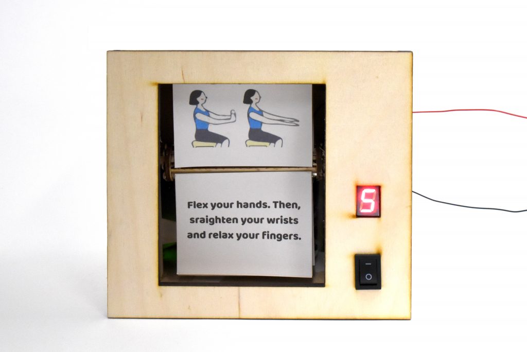
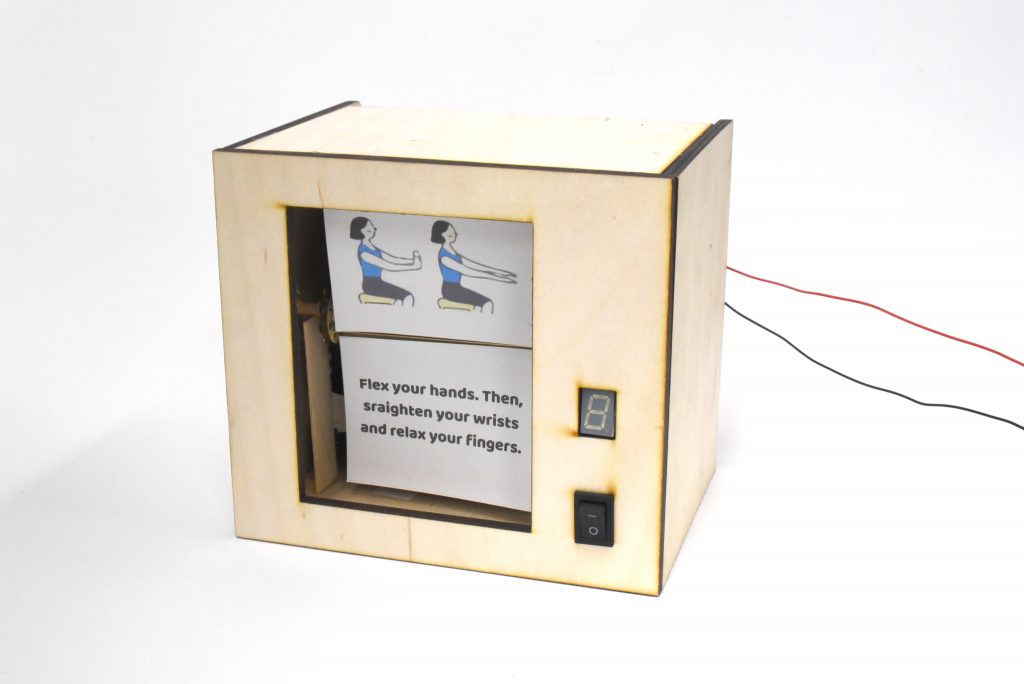
Device on, displaying the first stretch cards of the routine. The display counts from 1 to 5 every time a card flips.
Details
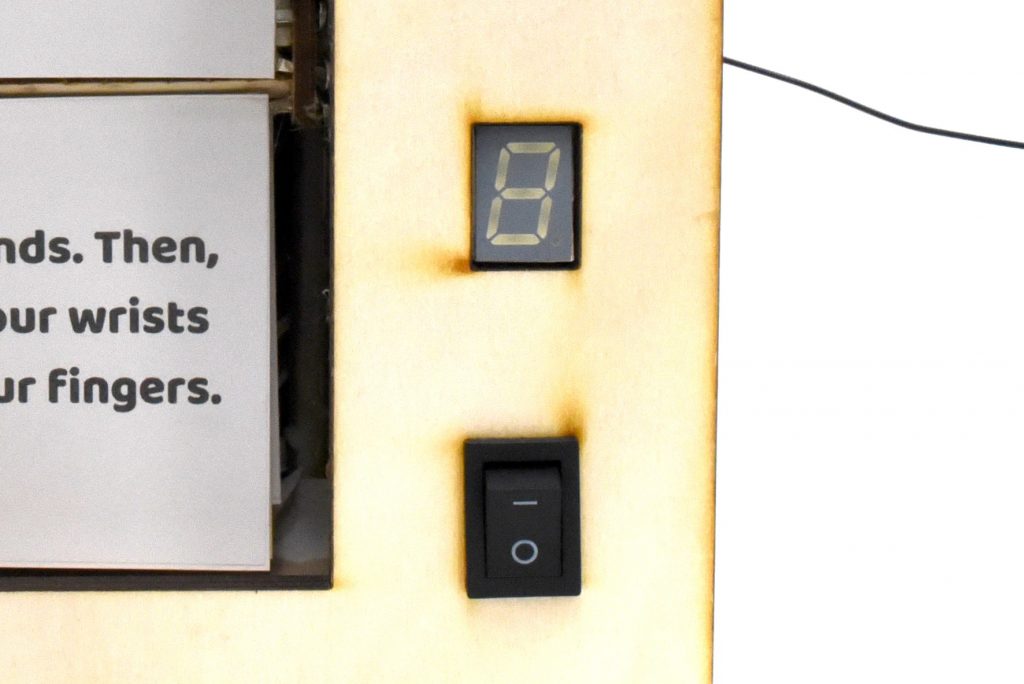
5-second timer display and switch.
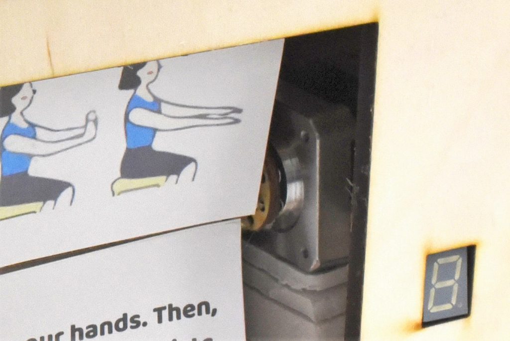
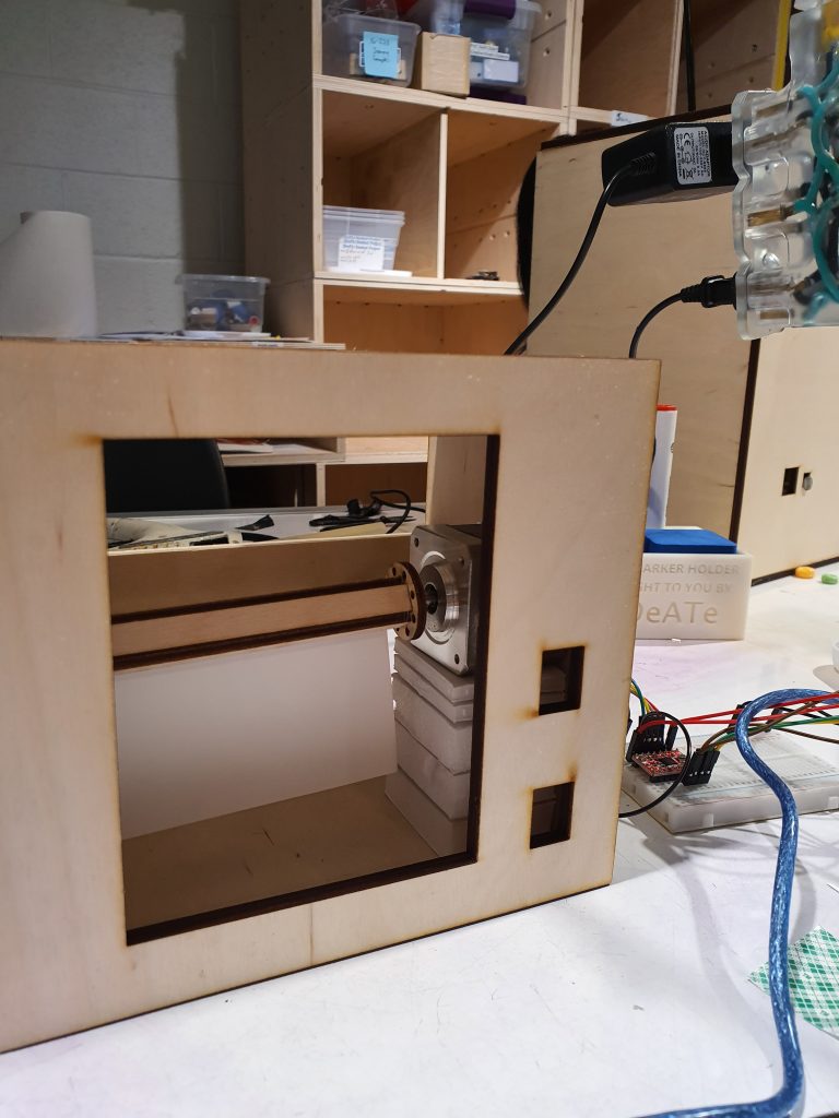
Connection of the cards to the mounted stepper motor. The cards are loosely held through each hole of the wooden circle with pins, and the circle is tightly connected to the motor. The motor turns the circle forward.
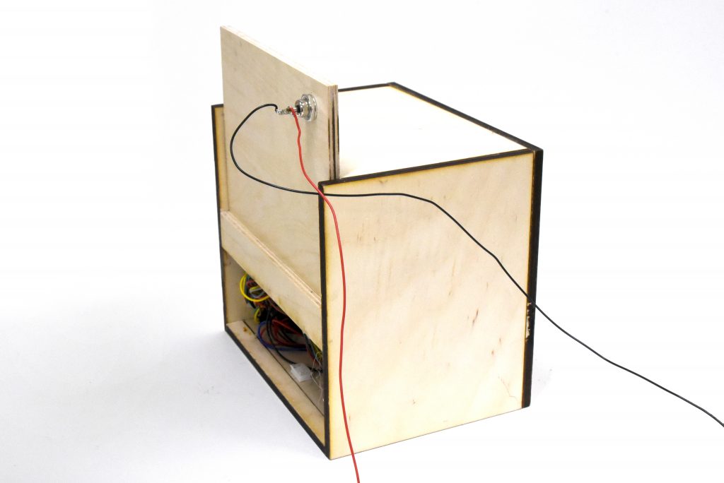
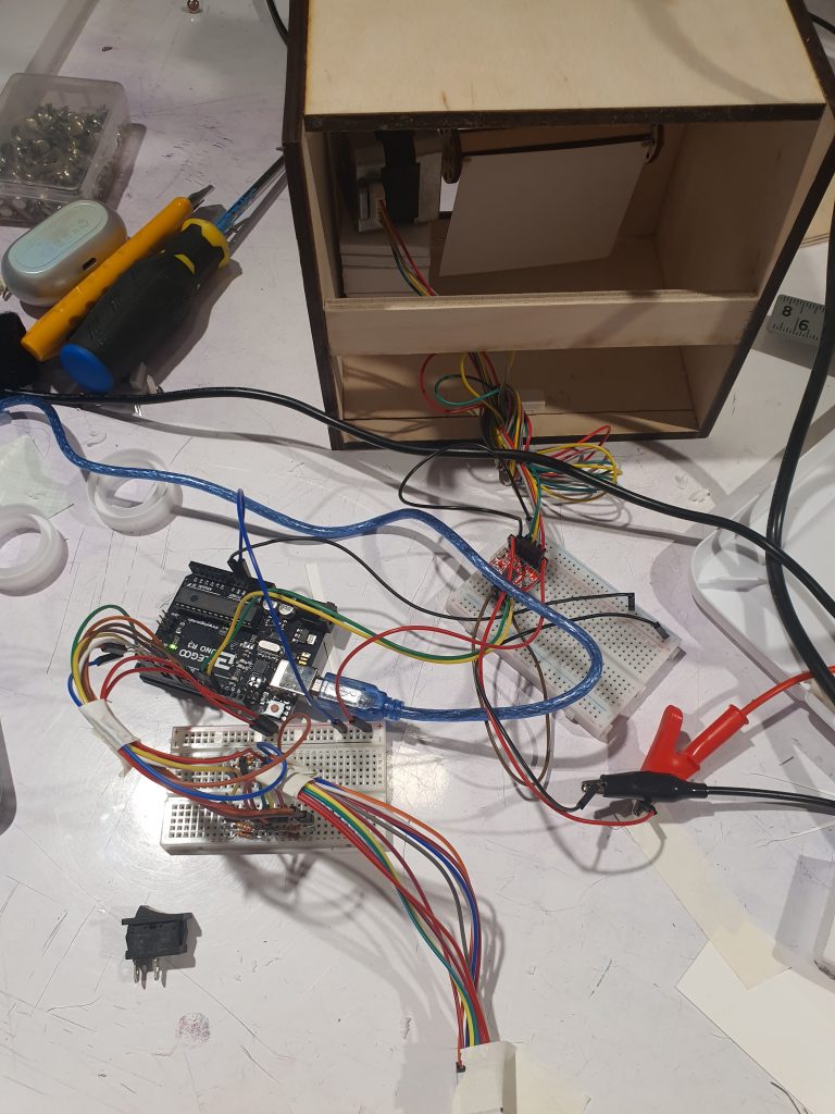
Device with the back board slid open. Back board is detachable for if the cards need replacement or if there is an internal problem.
Usage
Switch turned off when device is not in use. The whole device shuts down when the switch is turned off.
Process Images and Review
Throughout the project, there were some main redirection stages that I took to make the project more feasible or effective.
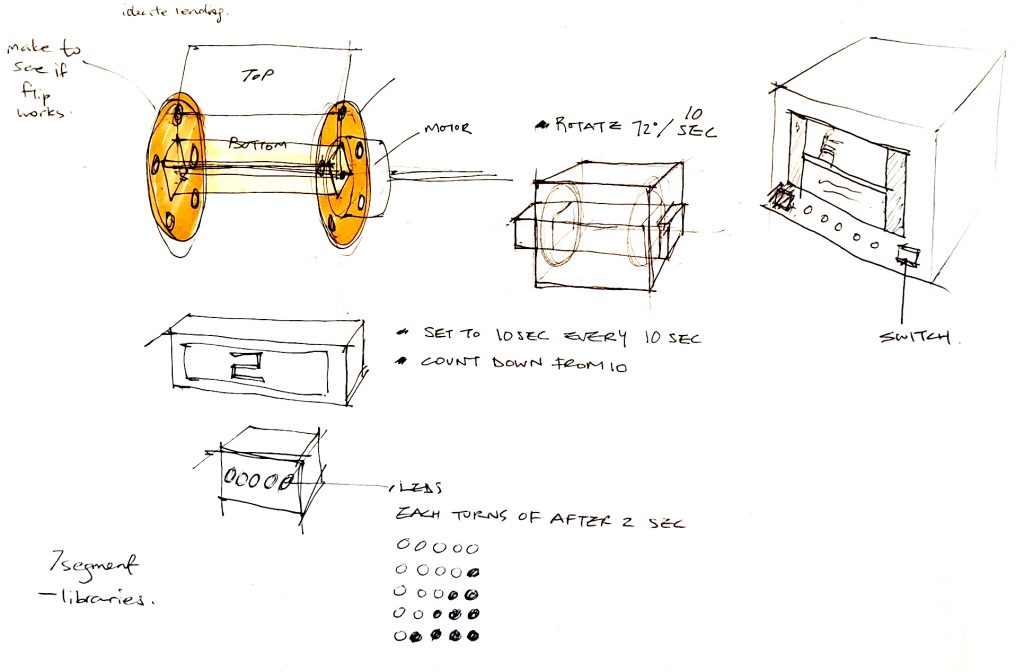
One part was determining how to display the 5-second timer. Initially, I thought about using an LCD screen, because that was the part that I was most familiar with. Then, I realized that it may not be necessary to use an LCD screen if I am just displaying 5 numbers, so I though about using 5 LEDs, that would visualize the numbers by turning on and off. Finally, I used a 7-segment display because this was a more concise and clearer way.
Initial plan: LCD screen.
Next plan: using 5 LEDs.
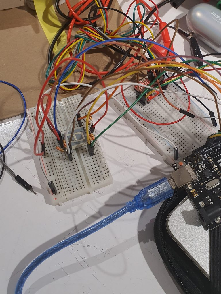
Final plan: using a 7-segment display.
Extending the 7-segment display connection out of the breadboard to put on the front plane of the box.
Secondly, another important part of the process was figuring out how to create the motor and cards move correctly. When I first brainstormed, I had my wooden circles much bigger and the rectangular prism quite big. After prototyping with chipboard and 3-D modelling, and knowing that I will be using 8 cards of specific sizes, I changed the dimensions. I could therefore avoid the whole structure becoming too big, or the movement becoming unnecessarily big, which would require the mechanism to be structurally very sturdy.
Furthermore, in the beginning, I wanted to have a dowel loosely holding the left side wooden circle, and the dowel tightly fitting into a plane that would also tightly fit inside the box. However, I just attached the dowel directly to the inside of the box.
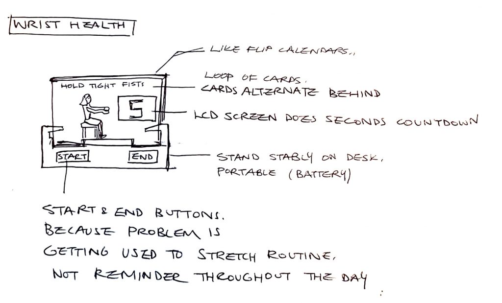
Initial sketch
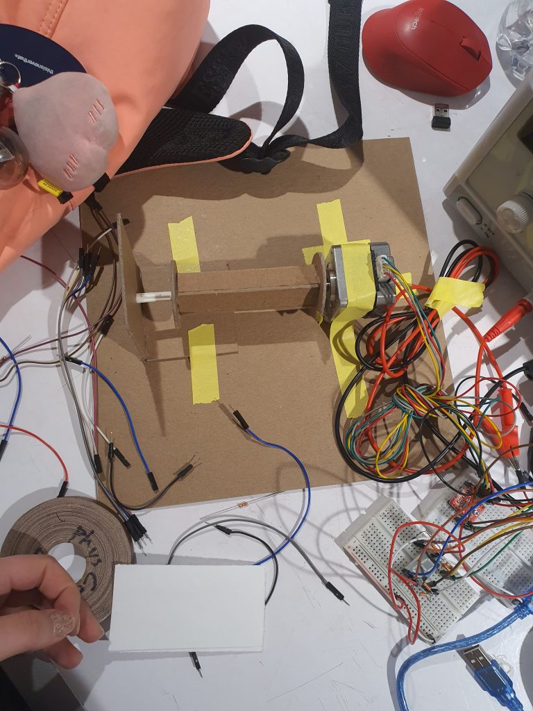
Larger-dimensions central wooden structure, and dowel fixed into a plane in the initial prototype.
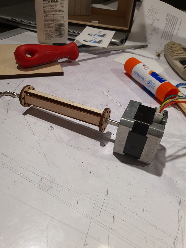
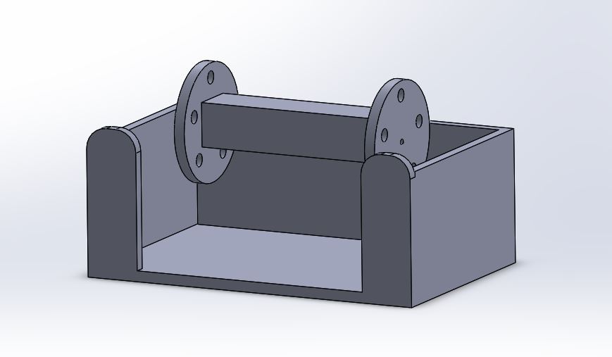
Central wooden structure with refined dimensions.
Assembly.
Lastly, a software challenge was when I had to utilize the non-blocking routine method for the timer instead of using a delay, so that it wouldn’t be a hard-coded fix, but a more precise system.
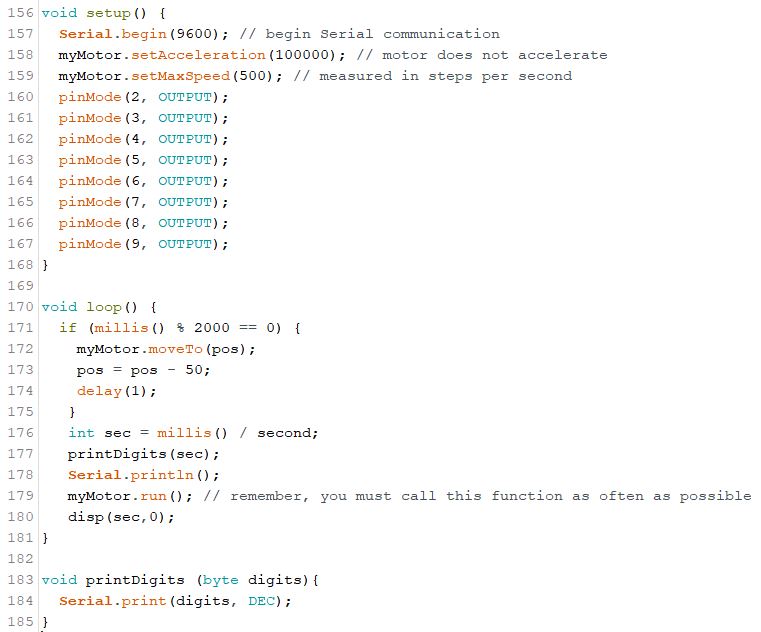
Initial attempt using delay
Discussion
Through this project, I could have an enjoyable experience of making my first individual physical computing project , and it gave me an opportunity to have thoughts and explorations that were meaningful to myself as a product designer. However, I was not entirely satisfied with the final physical product. When I chose this topic and brainstormed, I did not foresee some critical challenges that would take a relatively long time to resolve carefully. I think that some of the solutions that were not the best were well-pointed out during the in-class critique.
Some comments about my product was that it would be good “to make the current features more precisely,” or consider the user experience more because “it currently lacks a little bit of utility.” Although this device is for myself, I think some aspects are definitely not coherent enough. For example, the lifestyle reminders do not entirely make sense. It could have been clearer to just have stretch cards going in a loop, and perhaps incorporating the reminders as a different feature. Also, it could be better if I can make a setting in which I would go back to the first stretch of the loop, as opposed to just starting at whichever stretch the motor is showing whenever I turn the switch on.
A positive comment from one of my peers was that “the design of the cards moving is really fun and visually engaging.” Another feedback was that the design is “very neat.” I appreciate these because I also think I had a relatively successful result in getting the mechanism to work, and crafting the overall product. The mechanical part to get the movement working was not challenging for me. Nevertheless, I could have done a better job on the physical aspects if I had some more time to focus on them, after I had the software problems resolved. For instance, I ended up having much more wires than I had expected, so I had to cram in all the parts into the box, which I had laser-cut already in specific dimensions. Also, I can see some inner roughly-made parts from the outside through the window. If I were to make another iteration, I would definitely make the casing more carefully, and perhaps make the cards replaceable and more sturdily connected to the motor.
For me, taking initial attempts at software solutions was difficult for both the timer display part and the stepper motor part. I was able to learn many things as I asked for help from others, and started off with base code references from similar Arduino problems. As I understood other examples and pieces of advice, I could make changes of my own or write code that I could eventually get to work after some trial and error.
Technical Information
Schematic
![]()
Code
/* Carpal Tunnel Syndrome Stretch Coach
 * Youie Cho (minyounc)
 *
 * Description:
 * The code makes a card-flipping mechanism that flips various stretching guide
 * cards that help improve the symptoms of Carpal Tunnel Syndrome.The 7-segment
 * display helps the user to keep track of time for each stretch.
 *
 * Pin mapping:
 * pin   / mode   / description
 * ------/--------/---------------------------
 * 2-9     output   7-segment display segments
 * 12      output   motor steps
 * 13      output   motor direction
 *
 * References:
 * AccelStepper Library by Mike McCauley
 * Split flap display mechanism :https://imgur.com/a/0VAMZ
 * Blink without blocking coding: 60-223 course page
 * Stepper motor wiring and coding: 60-223 course page
 * 7-segment display timer wiring and coding:
 * https://create.arduino.cc/projecthub/arduino_uno_cool/create-a-7-segment-display-254ebe
 */

#include <AccelStepper.h> // Set up library for motor movement

const int STEP_PIN = 12; // A4988 "STEP" pin wired to pin 12
const int DIR_PIN = 13; // A4988 "DIRECTION" pin wired to pin 13

long second =  1000; // variable to represent 1000 milliseconds = 1 second
int pos = 0; // variable to store motor position
unsigned long timer = 0;// variable to keep track of passing time
const int wait = 5000; // number of milliseconds to wait between motor movements

AccelStepper myMotor(1, STEP_PIN, DIR_PIN); // create an AccelStepper motor object

bool dp = false; // boolean definition for timer (7-segment display)

// Setup for timer numbers 0 to 5
void disp(int num = -1, boolean dp = 0)
{
  digitalWrite(9, !dp);
  if (num == 0)
  {
    digitalWrite(2, 0);
    digitalWrite(3, 0);
    digitalWrite(4, 0);
    digitalWrite(5, 0);
    digitalWrite(6, 0);
    digitalWrite(7, 0);
    digitalWrite(8, 1);
  } else if (num == 1) {
    digitalWrite(2, 1);
    digitalWrite(3, 0);
    digitalWrite(4, 0);
    digitalWrite(5, 1);
    digitalWrite(6, 1);
    digitalWrite(7, 1);
    digitalWrite(8, 1);
  } else if (num == 2) {
    digitalWrite(2, 0);
    digitalWrite(3, 0);
    digitalWrite(4, 1);
    digitalWrite(5, 0);
    digitalWrite(6, 0);
    digitalWrite(7, 1);
    digitalWrite(8, 0);
  } else if (num == 3) {
    digitalWrite(2, 0);
    digitalWrite(3, 0);
    digitalWrite(4, 0);
    digitalWrite(5, 0);
    digitalWrite(6, 1);
    digitalWrite(7, 1);
    digitalWrite(8, 0);
  } else if (num == 4) {
    digitalWrite(2, 1);
    digitalWrite(3, 0);
    digitalWrite(4, 0);
    digitalWrite(5, 1);
    digitalWrite(6, 1);
    digitalWrite(7, 0);
    digitalWrite(8, 0);
  } else if (num == 5) {
    digitalWrite(2, 0);
    digitalWrite(3, 1);
    digitalWrite(4, 0);
    digitalWrite(5, 0);
    digitalWrite(6, 1);
    digitalWrite(7, 0);
    digitalWrite(8, 0);
  } else {
    digitalWrite(2, 1);
    digitalWrite(3, 1);
    digitalWrite(4, 1);
    digitalWrite(5, 1);
    digitalWrite(6, 1);
    digitalWrite(7, 1);
    digitalWrite(8, 1);
  }
}

void setup() {
  // Pin setup for timer
  pinMode(2, OUTPUT);
  pinMode(3, OUTPUT);
  pinMode(4, OUTPUT);
  pinMode(5, OUTPUT);
  pinMode(6, OUTPUT);
  pinMode(7, OUTPUT);
  pinMode(8, OUTPUT);
  pinMode(9, OUTPUT);

  Serial.begin(9600);// Begin serial monitor to monitor motor position (in steps)

  // myMotor settings to control motor behavior
  myMotor.setAcceleration(100000); // motor does not accelerate
  myMotor.setMaxSpeed(100); // maximum speed, measured in steps per second

  // Motor movement setting as 25/200 steps each time, so that it would go through
  // 8 positions to complete a revolution
  myMotor.moveTo(pos);
  pos = pos - 25;
}

void loop() {
  // Move the motor 25 steps every second
  if ((millis() - timer) > wait){
    Serial.println(pos);
    myMotor.moveTo(pos);
    pos = pos - 25;
    timer = millis();
  }

  // Call timer system function
  displayDigits();

  myMotor.run();
}


// Function to create a timer system
void displayDigits() {
  // Define the sec variable using millis
  int sec = millis() / second;

  myMotor.run();
  disp(sec % 5 + 1, 0); // When it reaches 5 seconds, it goes back to 1 second
  printDigits(sec);
  Serial.println();
}


// Function setting up the decimal parameter for second values
void printDigits (byte digits) {
  Serial.print(digits, DEC);
}
Comments are closed.