Overview
This top was designed to display the number of steps taken by the wearer.
The video above shows how the tank top works.
The numbers displayed at the pocket side shows the number of steps taken by the wearer.
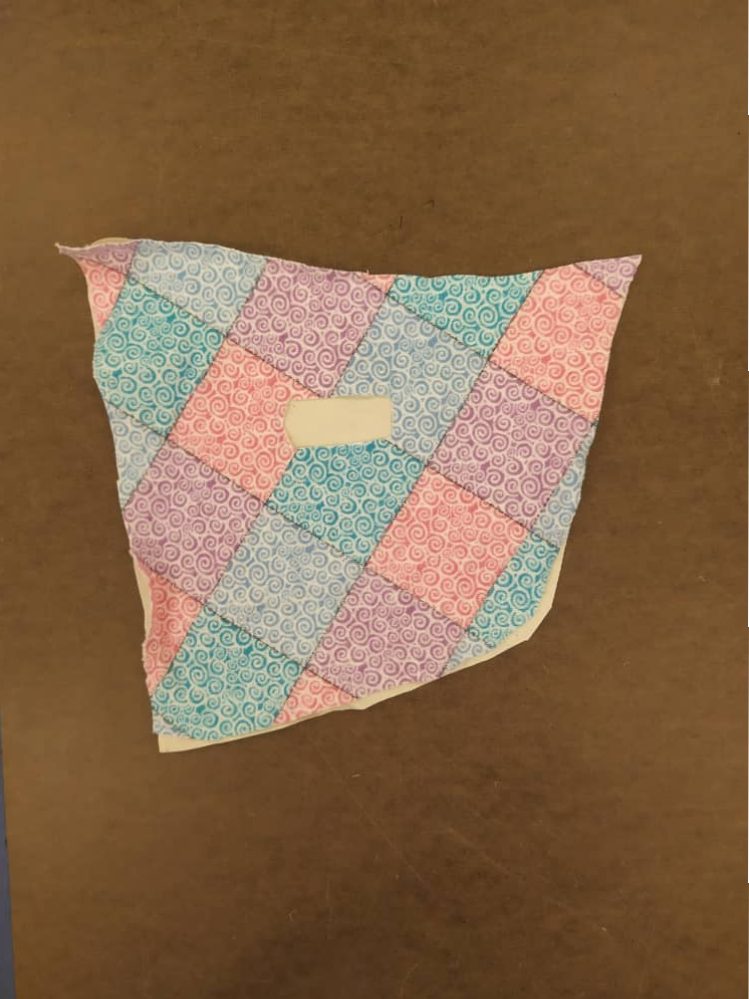
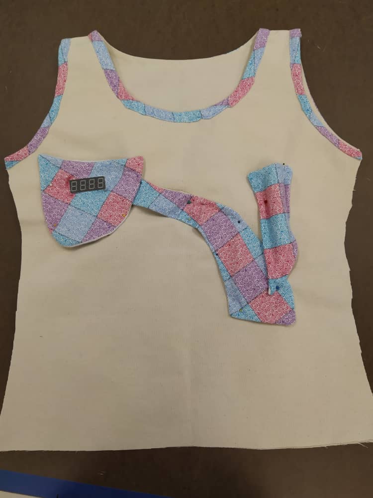
Pocket – The pocket was cut with a small box in the middle so that the 4 digit seven segment 0.56″ LED can easily fit inside. The pocket was lined with another fabric so that it can be used to turn the fabric inside out, hence giving it a neater finishing like every other tank top sold.

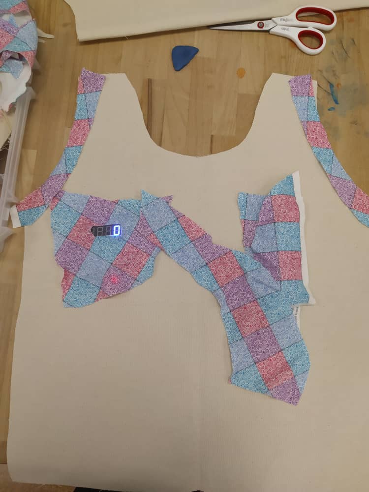
Back view – The neck and the two arm holes of the top was tapped with the flowery fabric.
Front view – This front view of the tank top has three patch segments. The first patch houses the circuit as a whole (that is, the arduino pro mini board, ADXL accelerometer, and the LED). The second patch covers or houses the wires that connects the circuit to the power supply (a 5 volts rechargeable power bank) which is in the third patch. These three patches were sewn together to form a whole patch that connects the three segment.
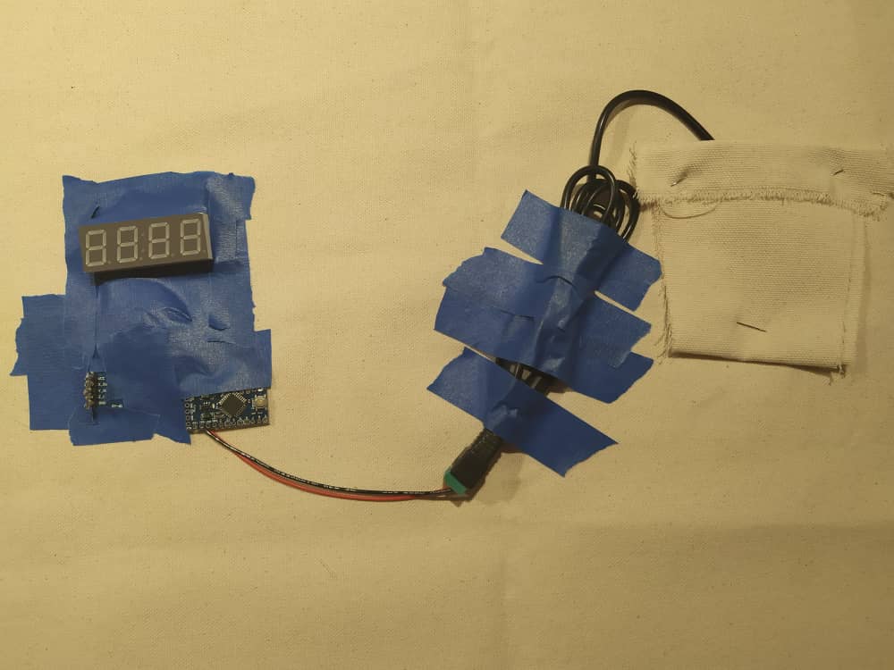
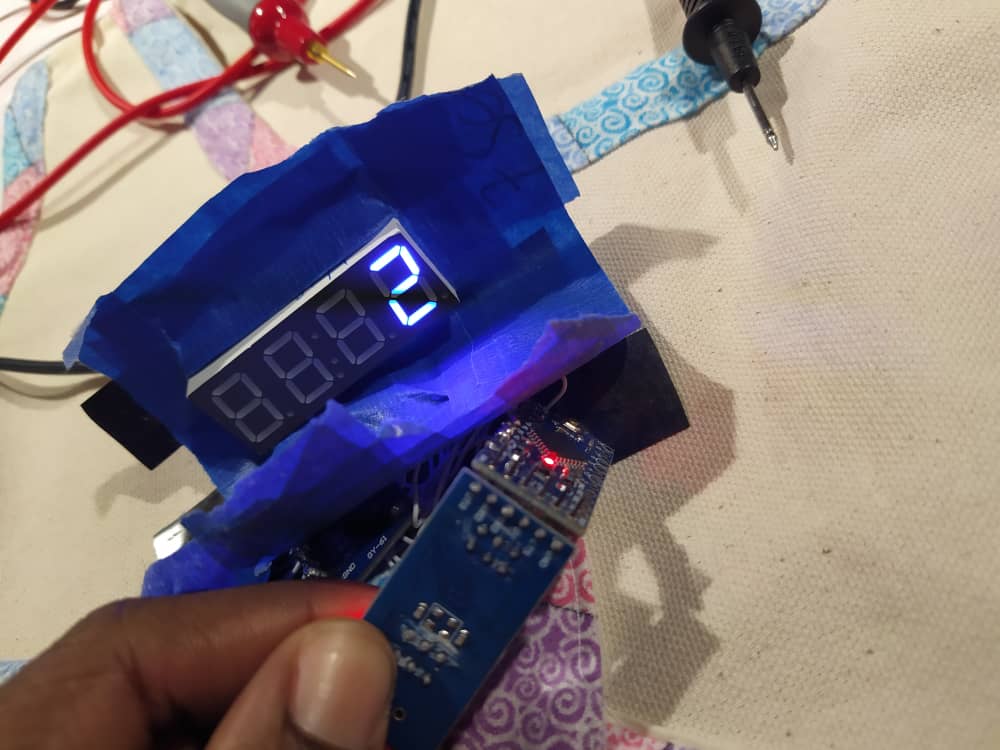
The early stage prototype where the parts were cello taped to the fabric.
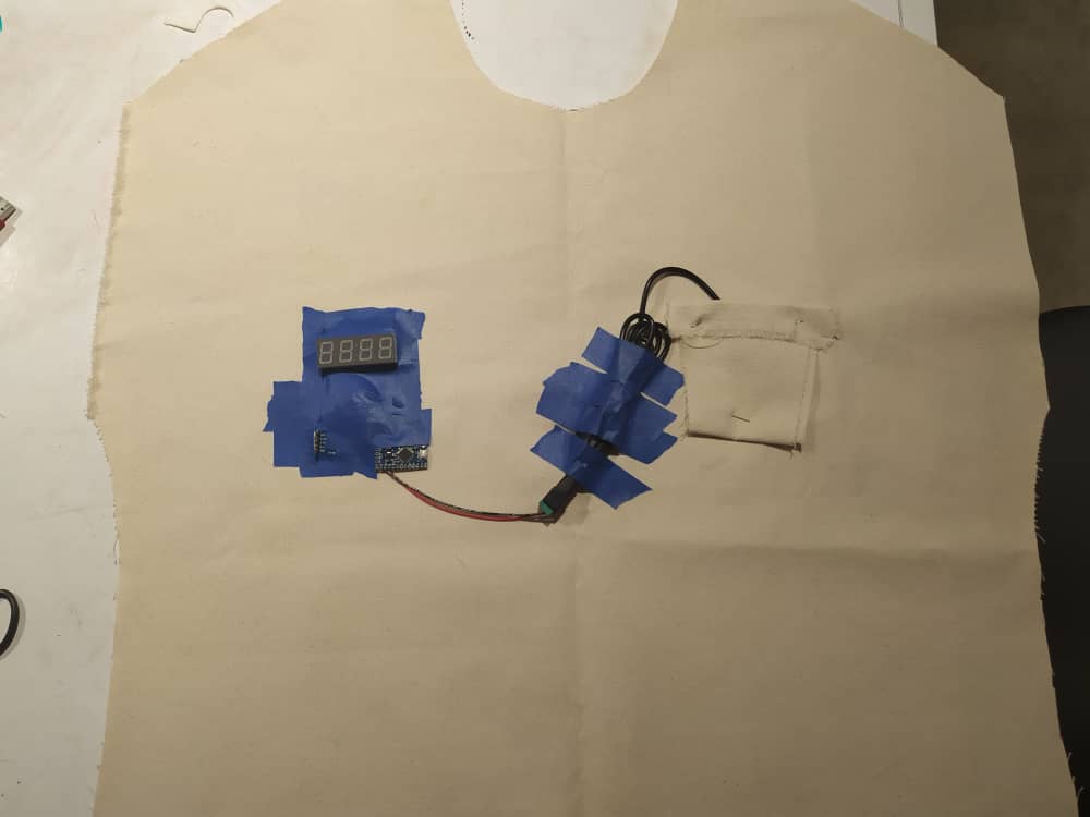
The first prototype designed to arrange the circuit on the tank top using cello tapes.
Process images and review
The three major components used: arduino pro mini board, ADXL335 accelerometer and 0.56″ 7-segment LED
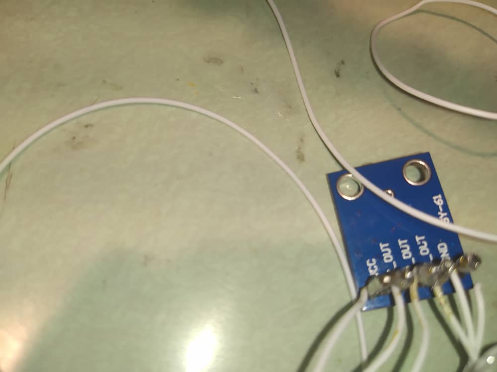
ADXL335 three axis accelerometer
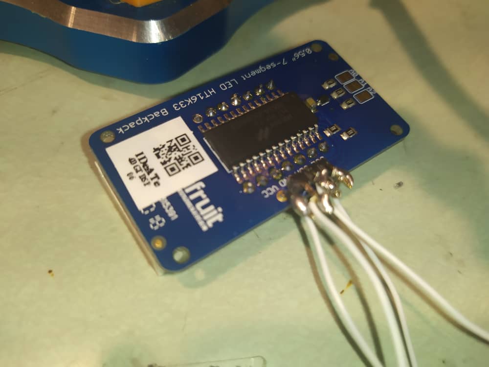
0.56″ 4-digit 7-segment LED
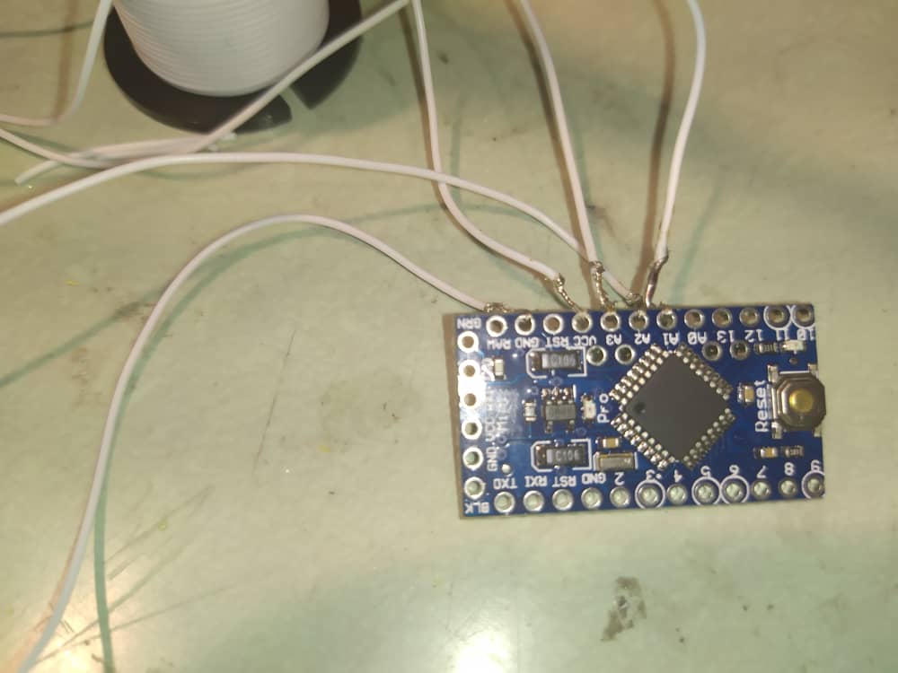
Arduino pro mini board
At the beginning of this project, the main focus is to start with getting the basic working functionality of the accelerometer. To achieve this, I started with the arduino uno board and the jumper wires connection because I was more comfortable using that. The circuit of this first circuit built is shown in the image below:
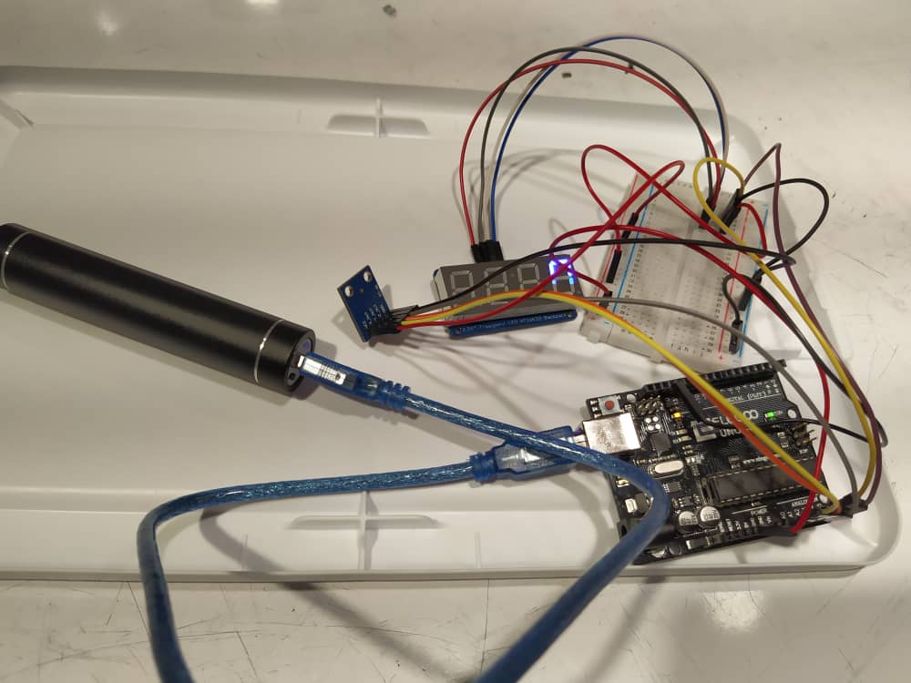
First circuit – Arduino Uno board circuit powered by the 5v rechargeable battery
After getting the basic functionality of the accelerometer, I wanted to transform the circuit to a more miniature circuit that can easily fit into a clothing/wearable. This could be done by firstly replacing the jumper wires with soft conductive wires and replacing the arduino uno board with the arduino pro mini board that is smaller. The image below shows the transformed circuit.
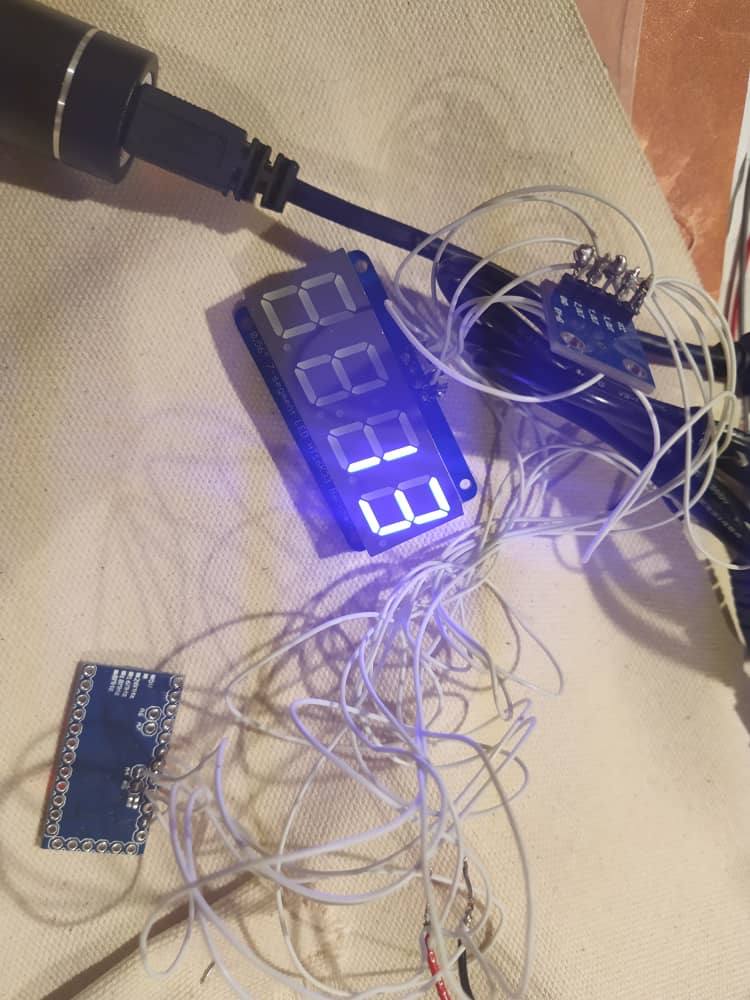
Transformed circuit with soft conductive wires and arduino pro mini instead of jumper cables and arduino uno board.
Loading the code unto the arduino pro mini board.
The video above shows the testing of the accelerometer using the arduino uno board.
Soldered the conductive wires on the four pins on the LED
The miniature circuit turned out as expected, which is to fit easily on a clothing. However, this was where I faced most of the challenges. Firstly, the soldering process was unexpectedly difficult. It could probably be either it is because this is my first soldering experience or because the components I used were so small for a newbie at soldering. At a point, I had an disconnection in my circuit, I tried to debug using the multi-meter but I could not figure it out for hours. This was really frustrating, but I was eventually able to identify this disconnection, which turned out to be a gnd disconnection on the arduino pro mini board.
Secondly, it was difficult at first to figure out the wearable friendly components that can be used to replace the electronic components in the first circuit. I had to interact with people that have knowledge about wearable technology (Garth and Olivia) who pointed me to the right materials to use to implement this project.
Thirdly, the project took a different shape because the initial plan was to make a stepometer tank top, but during the development process, I realized that the tank top does more of counting number of jumps than steps. That was quite funny though. It could easily pass for a jumpometer instead of a stepometer.
Discussion
Overall, the critiques were genuine and sincere. Most of the critiques agrees that the design is really beautiful which I agree with I say. I really love the aesthetic part of the project. One of the critique highlights that I should try and compare the steps taken from the shirt with that of the accelerometer on my phone. That would have been a great way to check if the steps are being counted accurately, if I had known earlier before the project presentation in class. Another critique suggested I use a solar panel instead of a power bank. I thought about that but I think that is too much of work for a second project in this course. However, going forward, in the future, I will definitely consider that.
I am really happy with the outcome of the project because of two major reasons. I have been able to achieve my goal that I came to this class with which is to successfully implement a wearable technology, no matter how basic its functionality is. This was achieved because I could recall that I wore that shirt to class on that day, which was pretty exciting. The second reason I am happy with the outcome of this project is that I was able to try soldering process for the very first time in my life and it worked! However, something I would love to improve in this project is to implement the code better. I could not do this because a larger amount of time was invested in the mechanical coupling than the software implementation.
One major thing I have learnt in this exercise is to speak out! This project actually pushed me out of my comfort zone to discuss with people, get ideas, and that really made my life easier. Also, prototyping helped me to get the pictorial view of what the end product would look like instead of having to imagine it in my mind.
Next steps if I am to build another iteration would be to think more in the line of soft-wearable friendly components to use instead of the mechanical components. Also, to learn more about the Adafruits tutorials and products online, since most of their products and lessons are wearable-related.
Furthermore, I will pay closer attention to the soldering process in order to avoid broken connection that is difficult to find.
Technical Information
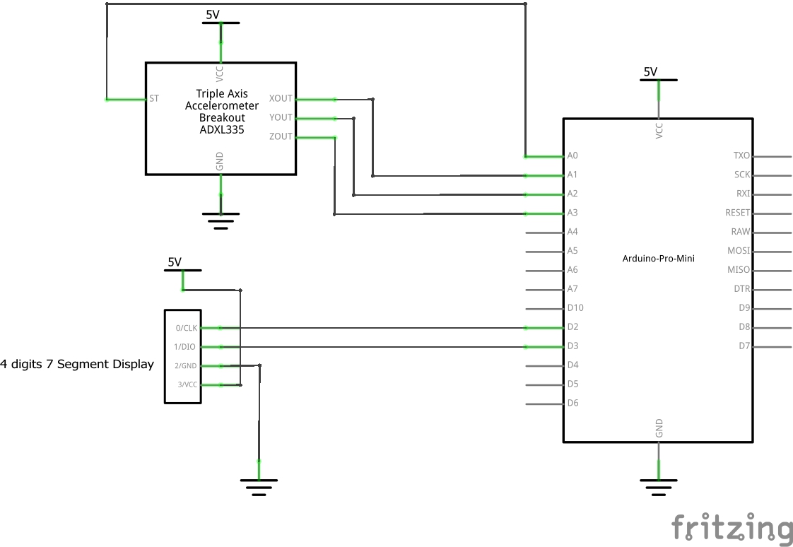
Counting steps schematic
- <span class="com">/*
- Project 2 - Counting steps tank top
- Olaitan Adisa (okadisa)
- Collaboration:
- // Resource used: http://arduinoprojectsforbeginners.blogspot.com/2018/07/measuring-steps-using-adxl335.html
- Challenge: The biggest challenge was more of the mechanical coupling rather than software.
- Description: The purpose is to create an assistive tank top that can display the number of steps taken on a 4
- digit seven segment LED attached to the shirt.
- Pin mapping:
- pin | mode | description
- -----|-------|------------
- A1 input x-axis
- A2 input y-axis
- A3 input z-axis
- A0 input ST
- 2 output CLK
- 3 output DIO
- */</span><span class="pln">
- </span><span class="com">#include</span><span class="pln"> </span><span class="str"><Wire.h></span><span class="pln"> </span><span class="com">// Enable this line if using Arduino Uno, Mega, etc.</span><span class="pln">
- </span><span class="com">#include</span><span class="pln"> </span><span class="str"><Adafruit_GFX.h></span><span class="pln">
- </span><span class="com">#include</span><span class="pln"> </span><span class="str">"Adafruit_LEDBackpack.h"</span><span class="pln">
- </span><span class="com">// initializing the constant variables</span><span class="pln">
- </span><span class="kwd">const</span><span class="pln"> </span><span class="kwd">int</span><span class="pln"> xpin </span><span class="pun">=</span><span class="pln"> A1</span><span class="pun">;</span><span class="pln">
- </span><span class="kwd">const</span><span class="pln"> </span><span class="kwd">int</span><span class="pln"> ypin </span><span class="pun">=</span><span class="pln"> A2</span><span class="pun">;</span><span class="pln">
- </span><span class="kwd">const</span><span class="pln"> </span><span class="kwd">int</span><span class="pln"> zpin </span><span class="pun">=</span><span class="pln"> A3</span><span class="pun">;</span><span class="pln">
- </span><span class="com">// initializing the variables</span><span class="pln">
- </span><span class="kwd">int</span><span class="pln"> step_count </span><span class="pun">=</span><span class="pln"> </span><span class="lit">0</span><span class="pun">;</span><span class="pln">
- </span><span class="kwd">float</span><span class="pln"> threshhold </span><span class="pun">=</span><span class="pln"> </span><span class="lit">500.0</span><span class="pun">;</span><span class="pln">
- </span><span class="kwd">float</span><span class="pln"> xval</span><span class="pun">[</span><span class="lit">100</span><span class="pun">]</span><span class="pln"> </span><span class="pun">=</span><span class="pln"> </span><span class="pun">{</span><span class="lit">0</span><span class="pun">};</span><span class="pln">
- </span><span class="kwd">float</span><span class="pln"> yval</span><span class="pun">[</span><span class="lit">100</span><span class="pun">]</span><span class="pln"> </span><span class="pun">=</span><span class="pln"> </span><span class="pun">{</span><span class="lit">0</span><span class="pun">};</span><span class="pln">
- </span><span class="kwd">float</span><span class="pln"> zval</span><span class="pun">[</span><span class="lit">100</span><span class="pun">]</span><span class="pln"> </span><span class="pun">=</span><span class="pln"> </span><span class="pun">{</span><span class="lit">0</span><span class="pun">};</span><span class="pln">
- </span><span class="kwd">float</span><span class="pln"> xavg</span><span class="pun">;</span><span class="pln">
- </span><span class="kwd">float</span><span class="pln"> yavg</span><span class="pun">;</span><span class="pln">
- </span><span class="kwd">float</span><span class="pln"> zavg</span><span class="pun">;</span><span class="pln">
- </span><span class="kwd">int</span><span class="pln"> steps </span><span class="pun">=</span><span class="pln"> </span><span class="lit">0</span><span class="pun">;</span><span class="pln">
- </span><span class="kwd">int</span><span class="pln"> state </span><span class="pun">=</span><span class="pln"> </span><span class="lit">0</span><span class="pun">;</span><span class="pln">
- </span><span class="com">// setting the LED</span><span class="pln">
- </span><span class="typ">Adafruit_7segment</span><span class="pln"> matrix </span><span class="pun">=</span><span class="pln"> </span><span class="typ">Adafruit_7segment</span><span class="pun">();</span><span class="pln">
- </span><span class="kwd">void</span><span class="pln"> setup</span><span class="pun">()</span><span class="pln"> </span><span class="pun">{</span><span class="pln">
- </span><span class="com">#ifndef</span><span class="pln"> __AVR_ATtiny85__
- </span><span class="typ">Serial</span><span class="pun">.</span><span class="kwd">begin</span><span class="pun">(</span><span class="lit">9600</span><span class="pun">);</span><span class="pln">
- </span><span class="typ">Serial</span><span class="pun">.</span><span class="pln">println</span><span class="pun">(</span><span class="str">"7 Segment Backpack Test"</span><span class="pun">);</span><span class="pln">
- </span><span class="com">#endif</span><span class="pln">
- matrix</span><span class="pun">.</span><span class="kwd">begin</span><span class="pun">(</span><span class="lit">0x70</span><span class="pun">);</span><span class="pln">
- pinMode</span><span class="pun">(</span><span class="pln">xpin</span><span class="pun">,</span><span class="pln"> INPUT</span><span class="pun">);</span><span class="pln">
- pinMode</span><span class="pun">(</span><span class="pln">ypin</span><span class="pun">,</span><span class="pln"> INPUT</span><span class="pun">);</span><span class="pln">
- pinMode</span><span class="pun">(</span><span class="pln">zpin</span><span class="pun">,</span><span class="pln"> INPUT</span><span class="pun">);</span><span class="pln">
- </span><span class="typ">Serial</span><span class="pun">.</span><span class="kwd">begin</span><span class="pun">(</span><span class="lit">9600</span><span class="pun">);</span><span class="pln">
- </span><span class="pun">}</span><span class="pln">
- </span><span class="kwd">void</span><span class="pln"> loop</span><span class="pun">()</span><span class="pln"> </span><span class="pun">{</span><span class="pln">
- </span><span class="kwd">int</span><span class="pln"> acc </span><span class="pun">=</span><span class="pln"> </span><span class="lit">0</span><span class="pun">;</span><span class="pln">
- </span><span class="kwd">float</span><span class="pln"> totvect</span><span class="pun">[</span><span class="lit">100</span><span class="pun">]</span><span class="pln"> </span><span class="pun">=</span><span class="pln"> </span><span class="pun">{</span><span class="lit">0</span><span class="pun">};</span><span class="pln">
- </span><span class="kwd">float</span><span class="pln"> totave</span><span class="pun">[</span><span class="lit">100</span><span class="pun">]</span><span class="pln"> </span><span class="pun">=</span><span class="pln"> </span><span class="pun">{</span><span class="lit">0</span><span class="pun">};</span><span class="pln">
- </span><span class="kwd">float</span><span class="pln"> xaccl</span><span class="pun">[</span><span class="lit">100</span><span class="pun">]</span><span class="pln"> </span><span class="pun">=</span><span class="pln"> </span><span class="pun">{</span><span class="lit">0</span><span class="pun">};</span><span class="pln">
- </span><span class="kwd">float</span><span class="pln"> yaccl</span><span class="pun">[</span><span class="lit">100</span><span class="pun">]</span><span class="pln"> </span><span class="pun">=</span><span class="pln"> </span><span class="pun">{</span><span class="lit">0</span><span class="pun">};</span><span class="pln">
- </span><span class="kwd">float</span><span class="pln"> zaccl</span><span class="pun">[</span><span class="lit">100</span><span class="pun">]</span><span class="pln"> </span><span class="pun">=</span><span class="pln"> </span><span class="pun">{</span><span class="lit">0</span><span class="pun">};</span><span class="pln">
- </span><span class="kwd">for</span><span class="pln"> </span><span class="pun">(</span><span class="kwd">int</span><span class="pln"> i </span><span class="pun">=</span><span class="pln"> </span><span class="lit">0</span><span class="pun">;</span><span class="pln"> i </span><span class="pun"><</span><span class="pln"> </span><span class="lit">100</span><span class="pun">;</span><span class="pln"> i</span><span class="pun">++)</span><span class="pln"> </span><span class="pun">{</span><span class="pln">
- xaccl</span><span class="pun">[</span><span class="pln">i</span><span class="pun">]</span><span class="pln"> </span><span class="pun">=</span><span class="pln"> </span><span class="kwd">float</span><span class="pun">(</span><span class="pln">analogRead</span><span class="pun">(</span><span class="pln">xpin</span><span class="pun">));</span><span class="pln">
- yaccl</span><span class="pun">[</span><span class="pln">i</span><span class="pun">]</span><span class="pln"> </span><span class="pun">=</span><span class="pln"> </span><span class="kwd">float</span><span class="pun">(</span><span class="pln">analogRead</span><span class="pun">(</span><span class="pln">ypin</span><span class="pun">));</span><span class="pln">
- zaccl</span><span class="pun">[</span><span class="pln">i</span><span class="pun">]</span><span class="pln"> </span><span class="pun">=</span><span class="pln"> </span><span class="kwd">float</span><span class="pun">(</span><span class="pln">analogRead</span><span class="pun">(</span><span class="pln">zpin</span><span class="pun">));</span><span class="pln">
- totvect</span><span class="pun">[</span><span class="pln">i</span><span class="pun">]</span><span class="pln"> </span><span class="pun">=</span><span class="pln"> sqrt</span><span class="pun">(((</span><span class="pln">xaccl</span><span class="pun">[</span><span class="pln">i</span><span class="pun">]</span><span class="pln"> </span><span class="pun">-</span><span class="pln"> xavg</span><span class="pun">)</span><span class="pln"> </span><span class="pun">*</span><span class="pln"> </span><span class="pun">(</span><span class="pln">xaccl</span><span class="pun">[</span><span class="pln">i</span><span class="pun">]</span><span class="pln"> </span><span class="pun">-</span><span class="pln"> xavg</span><span class="pun">))</span><span class="pln"> </span><span class="pun">+</span><span class="pln"> </span><span class="pun">((</span><span class="pln">yaccl</span><span class="pun">[</span><span class="pln">i</span><span class="pun">]</span><span class="pln"> </span><span class="pun">-</span><span class="pln"> yavg</span><span class="pun">)</span><span class="pln"> </span><span class="pun">*</span><span class="pln"> </span><span class="pun">(</span><span class="pln">yaccl</span><span class="pun">[</span><span class="pln">i</span><span class="pun">]</span><span class="pln"> </span><span class="pun">-</span><span class="pln"> yavg</span><span class="pun">))</span><span class="pln"> </span><span class="pun">+</span><span class="pln"> </span><span class="pun">((</span><span class="pln">zval</span><span class="pun">[</span><span class="pln">i</span><span class="pun">]</span><span class="pln"> </span><span class="pun">-</span><span class="pln"> zavg</span><span class="pun">)</span><span class="pln"> </span><span class="pun">*</span><span class="pln"> </span><span class="pun">(</span><span class="pln">zval</span><span class="pun">[</span><span class="pln">i</span><span class="pun">]</span><span class="pln"> </span><span class="pun">-</span><span class="pln"> zavg</span><span class="pun">)));</span><span class="pln">
- totave</span><span class="pun">[</span><span class="pln">i</span><span class="pun">]</span><span class="pln"> </span><span class="pun">=</span><span class="pln"> </span><span class="pun">(</span><span class="pln">totvect</span><span class="pun">[</span><span class="pln">i</span><span class="pun">]</span><span class="pln"> </span><span class="pun">+</span><span class="pln"> totvect</span><span class="pun">[</span><span class="pln">i </span><span class="pun">-</span><span class="pln"> </span><span class="lit">1</span><span class="pun">])</span><span class="pln"> </span><span class="pun">/</span><span class="pln"> </span><span class="lit">2</span><span class="pln"> </span><span class="pun">;</span><span class="pln">
- </span><span class="typ">Serial</span><span class="pun">.</span><span class="pln">println</span><span class="pun">(</span><span class="pln">totave</span><span class="pun">[</span><span class="pln">i</span><span class="pun">]);</span><span class="pln">
- delay</span><span class="pun">(</span><span class="lit">200</span><span class="pun">);</span><span class="pln">
- </span><span class="com">//calculating number of steps</span><span class="pln">
- </span><span class="kwd">if</span><span class="pln"> </span><span class="pun">(</span><span class="pln">totave</span><span class="pun">[</span><span class="pln">i</span><span class="pun">]</span><span class="pln"> </span><span class="pun">></span><span class="pln"> threshhold </span><span class="pun">&&</span><span class="pln"> state </span><span class="pun">==</span><span class="pln"> </span><span class="lit">0</span><span class="pun">)</span><span class="pln"> </span><span class="pun">{</span><span class="pln">
- steps </span><span class="pun">=</span><span class="pln"> steps </span><span class="pun">+</span><span class="pln"> </span><span class="lit">1</span><span class="pun">;</span><span class="pln">
- state </span><span class="pun">=</span><span class="pln"> </span><span class="lit">1</span><span class="pun">;</span><span class="pln">
- </span><span class="pun">}</span><span class="pln">
- </span><span class="kwd">if</span><span class="pln"> </span><span class="pun">(</span><span class="pln">totave</span><span class="pun">[</span><span class="pln">i</span><span class="pun">]</span><span class="pln"> </span><span class="pun"><</span><span class="pln"> threshhold </span><span class="pun">&&</span><span class="pln"> state </span><span class="pun">==</span><span class="pln"> </span><span class="lit">1</span><span class="pun">)</span><span class="pln">
- </span><span class="pun">{</span><span class="pln">
- state </span><span class="pun">=</span><span class="pln"> </span><span class="lit">0</span><span class="pun">;</span><span class="pln">
- </span><span class="pun">}</span><span class="pln">
- matrix</span><span class="pun">.</span><span class="kwd">print</span><span class="pun">(</span><span class="pln">steps</span><span class="pun">,</span><span class="pln"> DEC</span><span class="pun">);</span><span class="pln">
- matrix</span><span class="pun">.</span><span class="pln">writeDisplay</span><span class="pun">();</span><span class="pln">
- </span><span class="pun">};</span><span class="pln">
- delay</span><span class="pun">(</span><span class="lit">1000</span><span class="pun">);</span><span class="pln">
- </span><span class="pun">}</span>
Comments are closed.