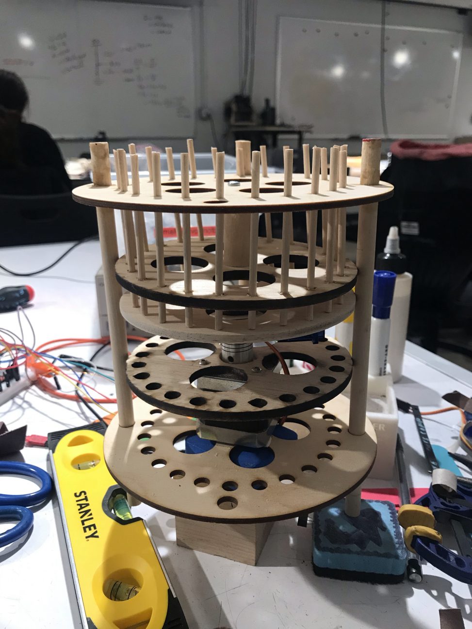

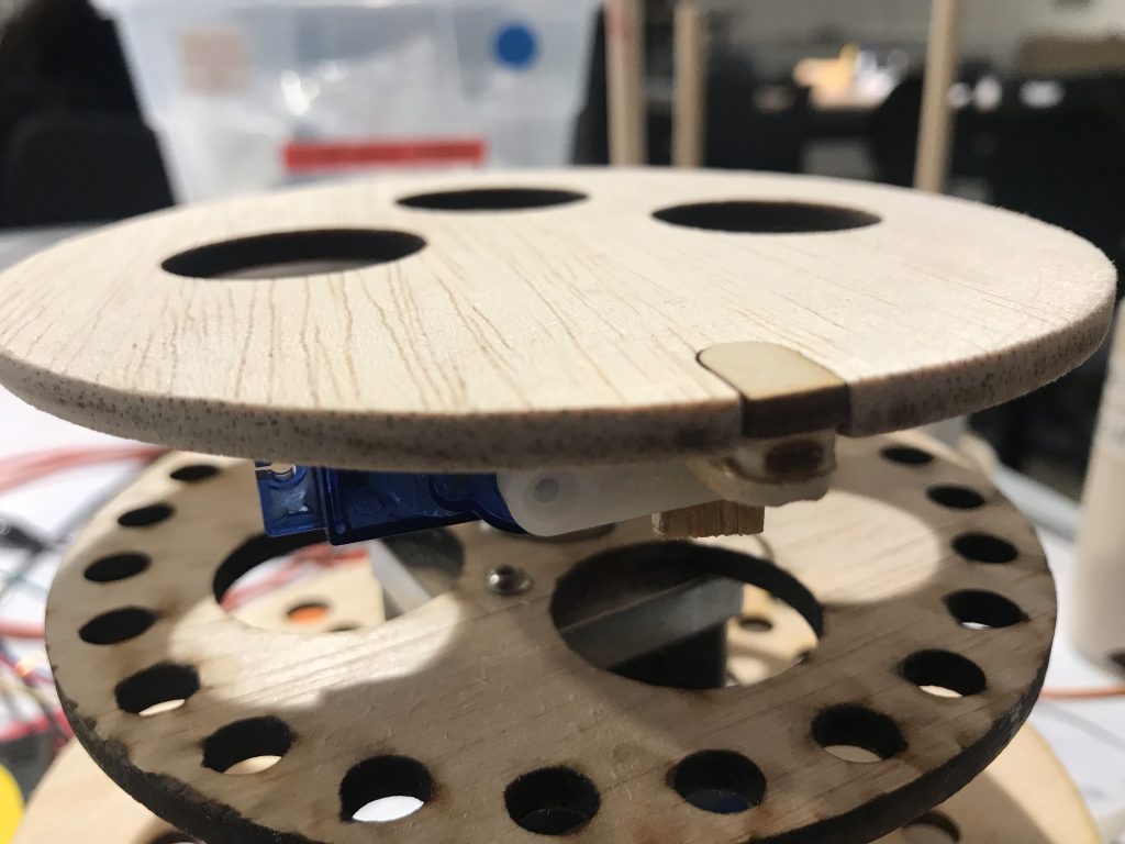
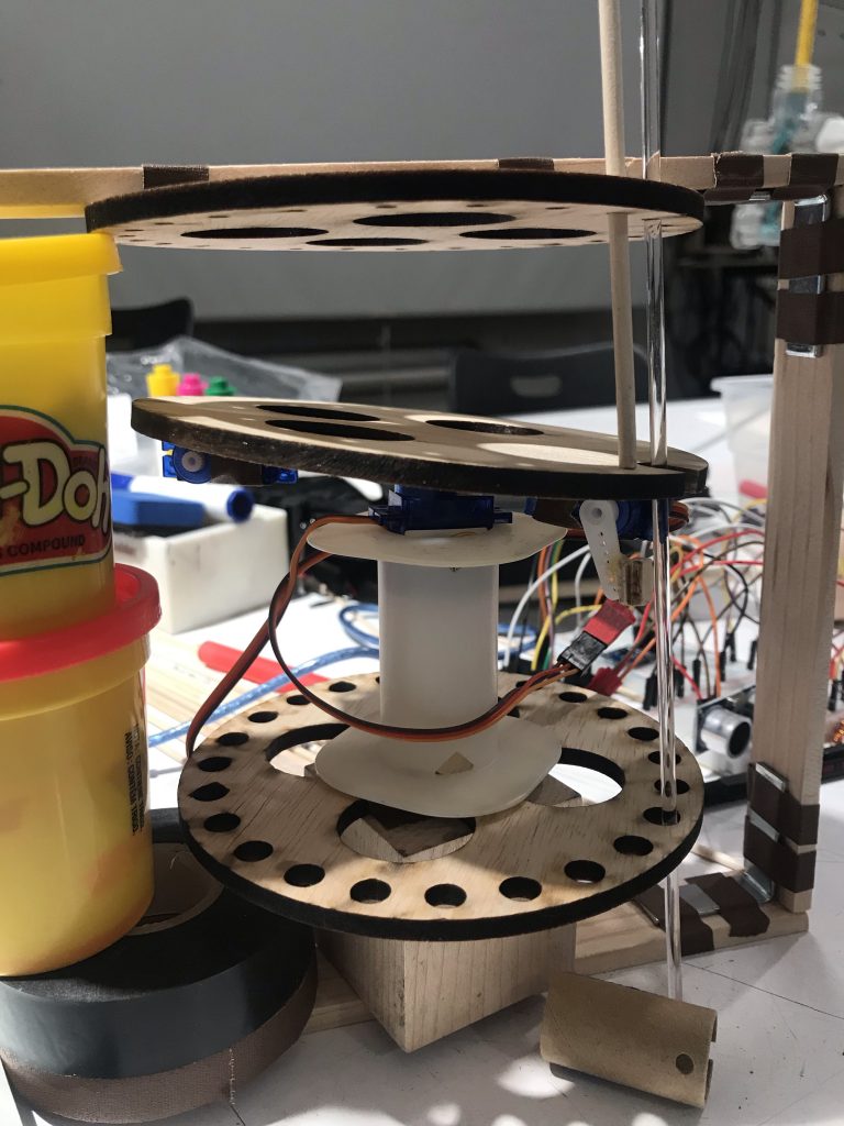
Final prototype.
This project aims to track the number of hours I am in my studio, as the 24 rods on the top floor fall to the bottom floor for every hour that I am sitting in my studio chair.
[high-quality images unavailable. Prototype does not work, so video is also unavailable.]
Sketches: How do you move 24 different parts with as little components as possible?
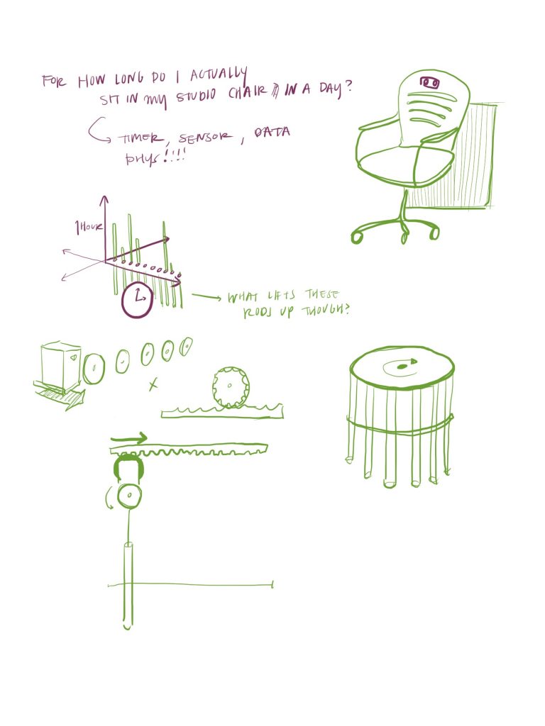
After consulting with Zach about my ideas in the initial check-in phase, I decided to go forth with making a physicalized data of my hours spent in my design studio. I sketched out numerous ideas to understand how to represent 24 hours with as little components as possible to reduce the number of “moving parts.”
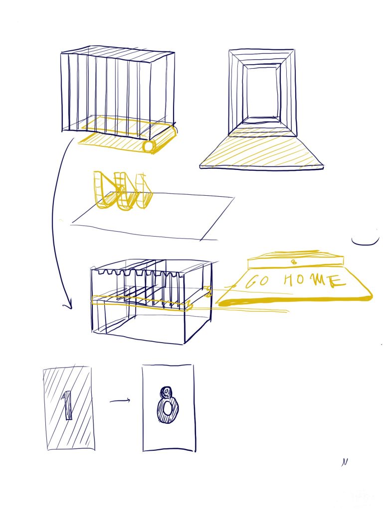
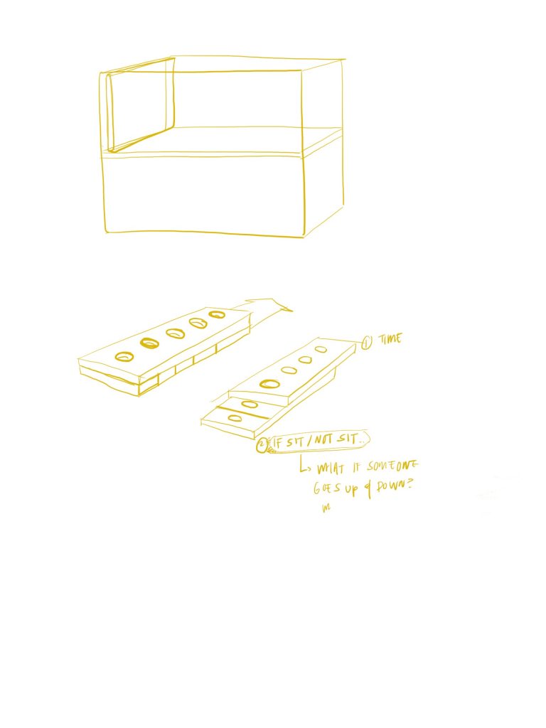
Idea 1: Servo moves panel in linear motion at an increment every hour. If in studio, panel falls. If out of studio, panel stays on top floor. Problem: how do I differentiate between the two phases?
Consideration of how to differentiate between on-off phase for idea 1.
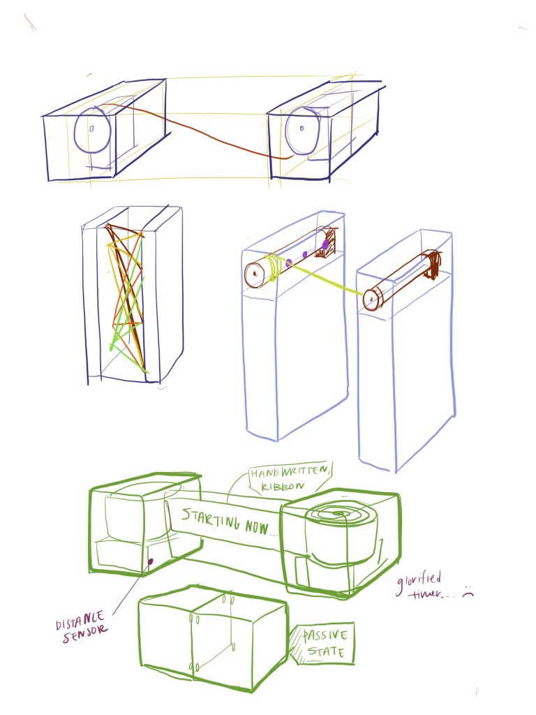
Idea 2: Ribbon wrapped around two servos, servos rotate every hour I am in studio, as ribbon reveals the number of hours I have been there. A glorified timer.
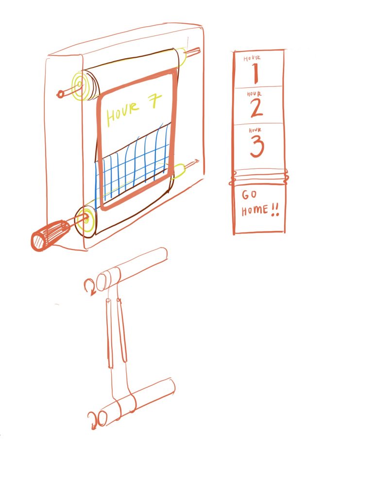
Iteration of Idea 2.
Another iteration of idea 2.
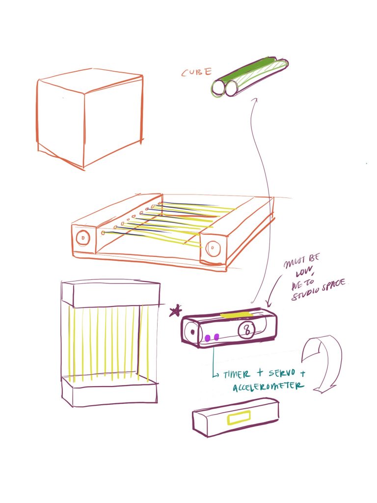
Redefining parameters. Distance sensor, 24 hours and on-off state had to be used.
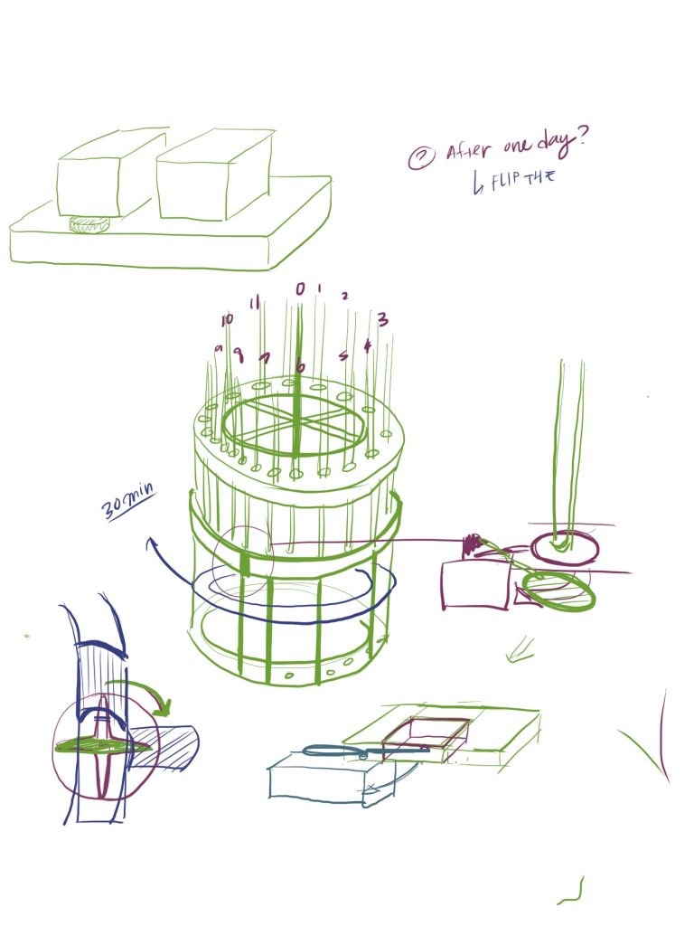
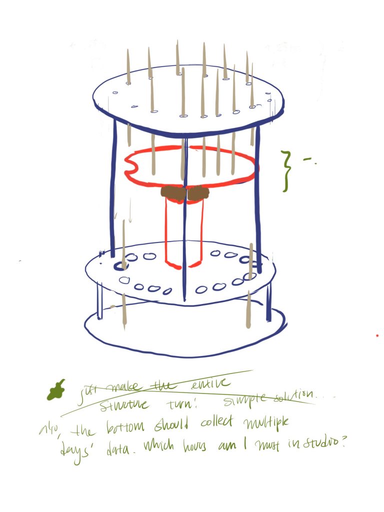
Final idea sketch
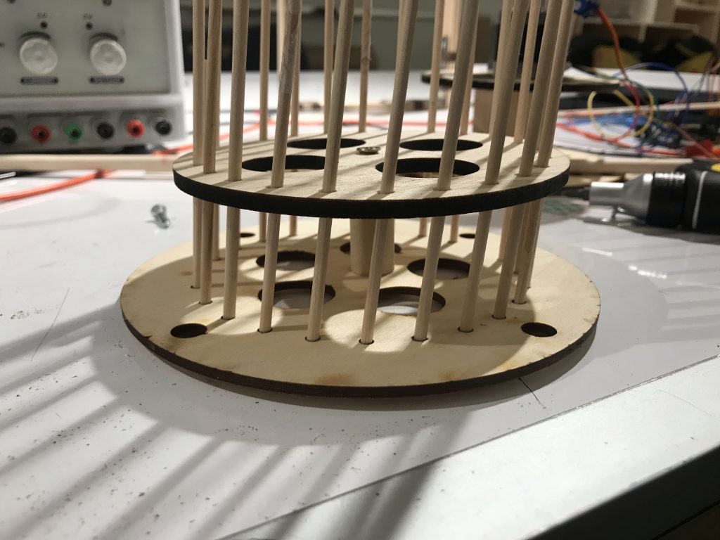
To explain how the project works: Top level contains 24 rods. Middle panel rotates every hour, with a small hole that opens and closes depending on whether I was in studio at that hour. If in studio, the rod falls to the bottom floor through the hole. If not, the rod remains on the top floor, as the hole never opens up.
Refined sketch. Figured out how to hold top panel in place
Decision 1:
A “flat” hole closer that can never open up, as the panel blocks the wooden piece from swiping down.
Hole closer: the anguish of making a flat surface that also doesn’t interfere with falling rods
The hole closer was critical to my design. Its essential function is to open up the hole when the ultrasonic ranger senses that I am in the seat, in order to let the rod drop onto the bottom floor.
I learned through trial and error the following rules to maintain the following rules in making the hole closer work.
-
- The wooden piece had to be perfectly flat when in the “closed” phase, such that the rods don’t get stuck at any bumps when the middle plane rotates.
- The wooden piece could not too big to interfere with a falling rod when in the “open” phase, or the rod will get stuck onto the wooden piece before falling to the bottom floor.
The problem was that I could not figure out how to fulfill both rules when positioning the servo in the right place. When the servo was located to the right of the hole, the wooden piece would be perfectly flat in the “closed” phase, but the rod would get stuck on the piece in the “open” phase.
Hole closer that closes flatly, but interferes with a falling rod in “open” state.
To solve this problem, when the servo was located towards the front of the hole (closer to the center), both rules would be satisfied, but the hole would not even open up in the first place due to the big size of the wooden piece.
Rotation is blocked due to position of the servo
I tried using soft pipe cleaners, rather than a hard wooden plane to solve the issue. The softness of the furs would reduce the “bumps” in either phase, even if not positioned entirely correctly. This did not work, however, as the pipe cleaner was too malleable, letting the rod go through as shown below:
Rod goes through the pipe cleaner attempt, causing the whole system to halt.
In the end, nothing really worked to solve this problem. Another fabrication method would have been better to open and close the hole, but as I had already cut out the piece on laser cutter, I could not find another way around it.
Decision 2:
Continuous servo motor → stepper motor for flatter surface and greater precision
A continuous servo motor was initially used to rotate the middle plane, but there were two problems:
-
- One, I couldn’t achieve the desired angles for each stop, as the servo motor can only be controlled by the speed at which it moves.
- Two, the servo motor was too flimsy, that it didn’t hold the plane at a perpendicular angle. That messed with the precision of the hole alignment from panel to panel.
Servo motor unable to maintain a flat surface, making the rods difficult to pass through the holes
I then opted for using the stepper motor, which gave me a much greater precision. I blew up three A4988 chips in the process, however. The first time, I had circuits that flipped the ground and 5v. I couldn’t figure out the problems for the second and third times though. I lowered the voltage to 10 volts, rather than the maximum 12 volts for the stepper motor, just in case I don’t blow up another board.
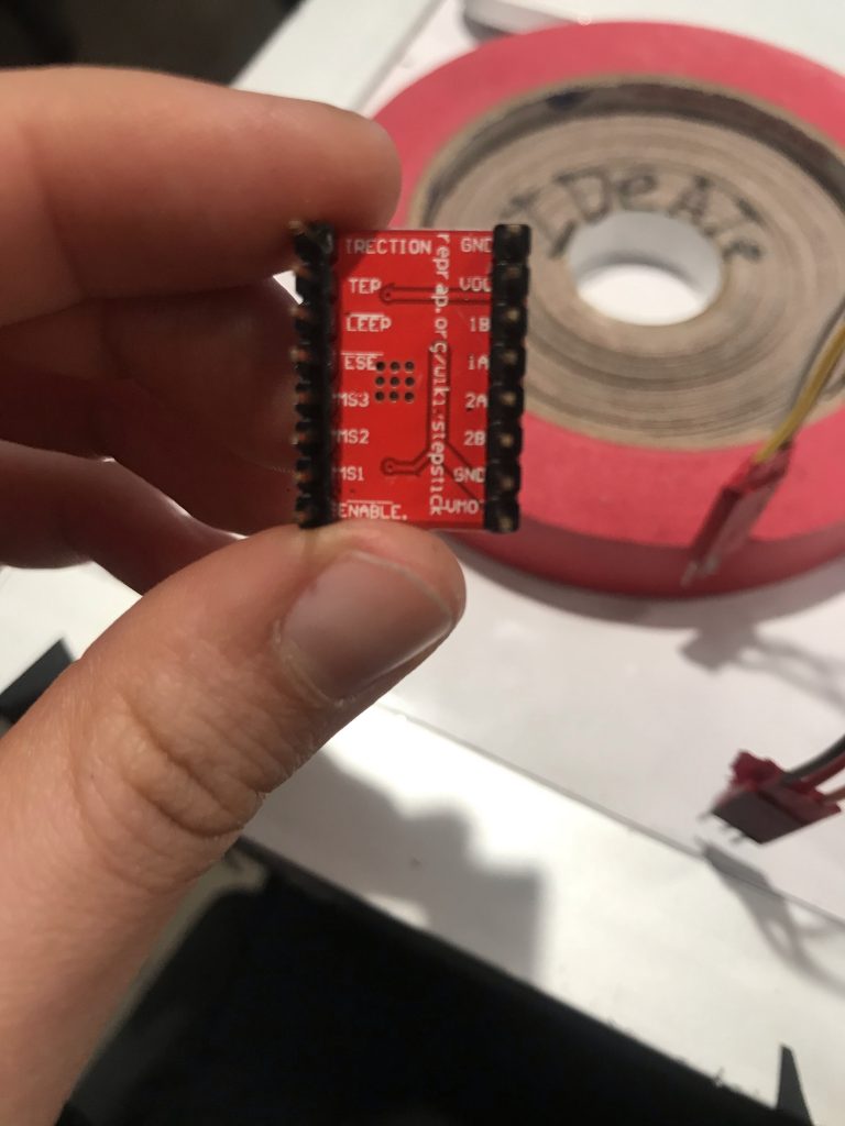
A4988 chip used to interface with the stepper motor. I ended up blowing up three of these.
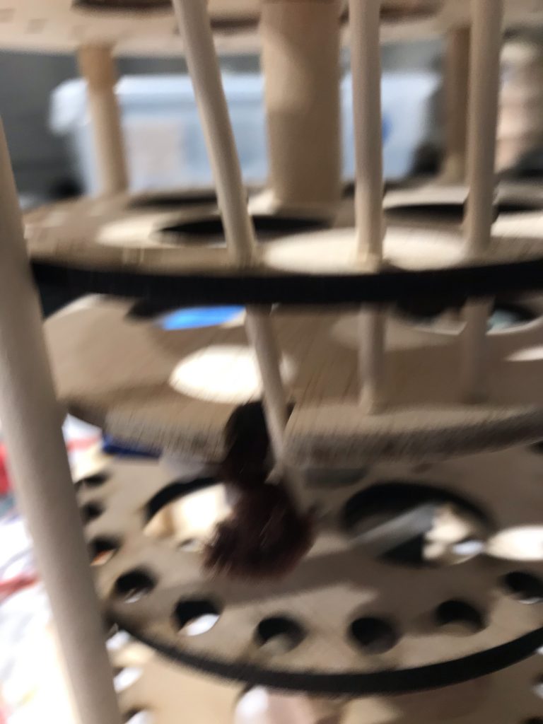
Stepper motor caused the plane to rotate uncontrollably due to the high vibration.
Rotation problem fixed by bolting the plane down to the motor.
Stepper motor gave me greater control over hole alignment. I figured out on code how to rotate the plane by 360/24 degrees. The hole alignment now worked from plane-to-plane.
Other moments in process
Rod falls through the hole well. One of few successful tries.
Initial, initial prototype. Tested out string gear for Idea 1.
Tested out how rods would fall if middle plane was moved.
Realization: Even the slightest tilt (as shown) can cause rods to fall out of place. The top plane had to be revolted to fix this error.
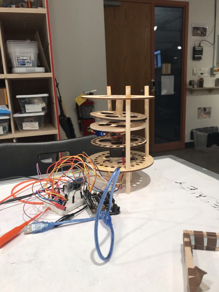
Final prototype. Panels are held together perpendicularly through thick wooden poles
Response
I was quite frustrated leading up to the final critique day, as I was staying up for three whole nights in the physical computing lab trying to make the project work. I had spent so long in the earlier phase trying to design how to represent 24 different data points using as few components as possible, that when I landed on a sketch that worked in theory, I was determined to follow through with my plan.
What I should have realized early on is that my prototype plan had way too many mechanical problems. I thought I had found a simple solution to my seemingly unsolvable problem, but it turned out that even the “simple” solution had way too many parts to control.
For one, it required a significant amount of precision in making sure each of the 24 rods to fall through the holes in the desired manner. Not only that, making the hole-closer mechanism was excruciatingly difficult, but I could not turn back on the design late into the prototype phase, as I had already laser cutted the piece for the specific purpose I had designed for. As a result, my piece never ended up working for the final crit day.
I got some feedback from my peers during the class critique to tackle those problems. Lots of advice were given to help with the problem of the rod getting stuck between the wooden planes, as well as making sure they fall into the right holes in the bottom layer.
“Nice concept, where you are able to visualize how long you have worked plays with your guilt. For the wood stick falling issue, you could use a tube that will lead the wood stick to certain place, so other factors like slight movement of wind doesn’t make the stick be stuck in the hole. Also place a little tray or holder to catch the wood sticks. “
- The tube idea was something I had not thought of before. Definitely worth a try if I could have another go at this project. I wonder if the tubes become another obstacle that the rods hit against though, however, making the rods get stuck at an angle within the hole before exiting through the next hole. I find this to be very likely based on my experience with the project, although using a heavier rod, such as one made of steel or plastic, may help solve this issue.
“The project aesthetic is really nice. Everything looks precisely measured which makes it look really good! Maybe try to have a function that wiggles around until the sticks fall”
- I actually did try making the stepper motor “wiggle” at a stop, to help with the stick falling. I spent hours trying to figure out the right code for it and ended up not working. I could not figure out why in the given time span, but the motor would rotate around by over 50 degrees, rather than moving 5 degrees back and forth from the original spot as desired.
Looking back on the process now, I realize that I should have been less ambitious with my approach, even if it made sense in “theory” and in my sketches. Rather than simulating my project in my brain that clearly defied all rules of physics, I should have changed my project plan soon as I found myself working on a minor problem for 8 straight hours.
I thought that my project was very simple due to the little amount of effort it takes on code, but it relied too much on physical fabrication for my idea to work well. One of the biggest problems was that I had no way of knowing how the rods (the moving part that has no direct ties to any Arduino component) would move. I’m thinking that maybe I should have taken the time to build the gear mechanism on Fusion360, where two gears can control the x and y direction of a servo, so that I have full control over any moving part that requires precision. From that mechanism on, I could have built a more manageable project by, say, just having the servo push 24 panels like a domino, where each panel has no dependency on the entire system. (Some rods currently get stuck between panels, stopping the middle plane from rotating to the next hole.)
Also, I could have been more open to a digital representation of time (ex: using LED bulbs) once I realized that controlling the rods became too difficult, and focused more of my attention on controlling the distance sensor on code as well as covering up all the electronics. The problem seems to be that I made no compromises to make my project more manageable, resulting in 3 all-nighters and a failed project at best.
I’m not sure if going forward with my current model is the best idea. I was pretty distraught for most of my Spring break thinking of how unsuccessful my project was, so I am mentally exhausted from just looking at my project now. The idea of keeping track of my hours at studio through data physicalization is promising, but perhaps not through 24 different rods. I might give it another go when I regain more confidence in physical computing through other, more plausible projects.
Schematic

Code submission
/* Data Physicalization of Studio Hours
 * Elizabeth Han (yoonjuh)
 *
 * Description:
 * This code achieves two functions in the overall project. First, it changes
 * the degrees of a servo depending on the distance sensor reading in order to
 * close the hole in the middle panel. Second, it rotates the middle plane by
 * 360/24 degrees every hour (currently set to 3 seconds for testing purposes) using the
 * stepper motor.
 *
 * Pin mapping:
 * pin   / mode   / description
 * ------/--------/---------------------------
 * 12     input    ultrasonic sensor trigger
 * 11     input    ultrasonic sensor echo
 * 10     output   servo
 * 7      output   stepper motor steps
 * 8      output   stepper motor direction
 *
 * References:
 * Stepper motor: https://courses.ideate.cmu.edu/60-223/s2020/tutorials/stepper
 * TaskTimer: https://courses.ideate.cmu.edu/60-223/s2020/tutorials/code-bites#blink-without-blocking
 */

#include <NewPing.h>
#include <Servo.h>
#include <AccelStepper.h>
#include <Wire.h>

#define TRIGGER_PIN  12  // Arduino pin tied to trigger pin on the ultrasonic sensor.
#define ECHO_PIN     11  // Arduino pin tied to echo pin on the ultrasonic sensor.
#define MAX_DISTANCE 400 // Maximum distance we want to ping for (in centimeters). Maximum sensor distance is rated at 400-500cm.

NewPing sonar(TRIGGER_PIN, ECHO_PIN, MAX_DISTANCE); // NewPing setup of pins and maximum distance.

//set up servo
Servo SwingServo;
const int SERVOPIN2 = 10;

//set up step motor
const int STEP_PIN = 7;
const int DIR_PIN = 8;
AccelStepper myMotor(1, STEP_PIN, DIR_PIN);

int steps = 0;
int pos = 1;

//set up timers
unsigned long taskTimer = 0;
unsigned long taskTimer2 = 0;
unsigned long taskTimer3 = 0;
const int INTERVAL = 4000; //check sitting as frequently as possible
const int SWINGINT = 4000;
const int MOTORINT = 3000; //1 hour
const int WIGGLEINT = 500;
int counter = 0;
int prevCounter = -1;

bool sitting = false;
int plus = 0;
int minus = 0;

void setup() {
  Serial.begin(9600);

  SwingServo.attach(SERVOPIN2);
  myMotor.setMaxSpeed(6000); // measured in steps per second
  myMotor.setAcceleration(10000); // measured in steps per second squared
}


void loop() {
  // distance sensor --> hole closer
  //determines if person is sitting or not in seat, opens up hole

  int distance = sonar.ping_cm();

  if (millis() - taskTimer >= INTERVAL) {
    if (distance <= 10) {
      SwingServo.write(0);
      sitting = true;
    }
    else {
      SwingServo.write(90);
      sitting = false;
    }
    taskTimer = millis();
  }

  //swing loop
  //wiggles board to make sure rod goes down when in sitting state

    if (millis() - taskTimer2 >= SWINGINT) {
      if (sitting == true and prevCounter != counter) {
        Serial.println("swing");

        plus = steps + 1;
        myMotor.moveTo(plus);
        myMotor.run();
        delay(1000);
        Serial.print("swing1 current position: ");
        Serial.println(myMotor.currentPosition());

        minus = steps - 1;
        myMotor.moveTo(minus);
        myMotor.run();
        delay(1000);

        Serial.print("swing2 current position: ");
        Serial.println(myMotor.currentPosition());
      }
      prevCounter = counter;
      taskTimer2 = millis();
    }


  //stepper motor loop
  //turns every 360/24 degrees

  int degreesPerHour = 200 / 24; //200 steps in motor, therefore 200/24

  if (millis() - taskTimer3 >= MOTORINT and sitting == true) {
    counter += 1;

    if (counter == 24) {
      pos *= -1;
      counter = 0;

    }

    steps += degreesPerHour * pos;
    myMotor.moveTo(steps);

    taskTimer3 = millis();

    Serial.print("counter: ");
    Serial.println(counter);
    Serial.print("current position: ");
    Serial.println(steps);

  }

  myMotor.run();

}
Comments are closed.