Introduction
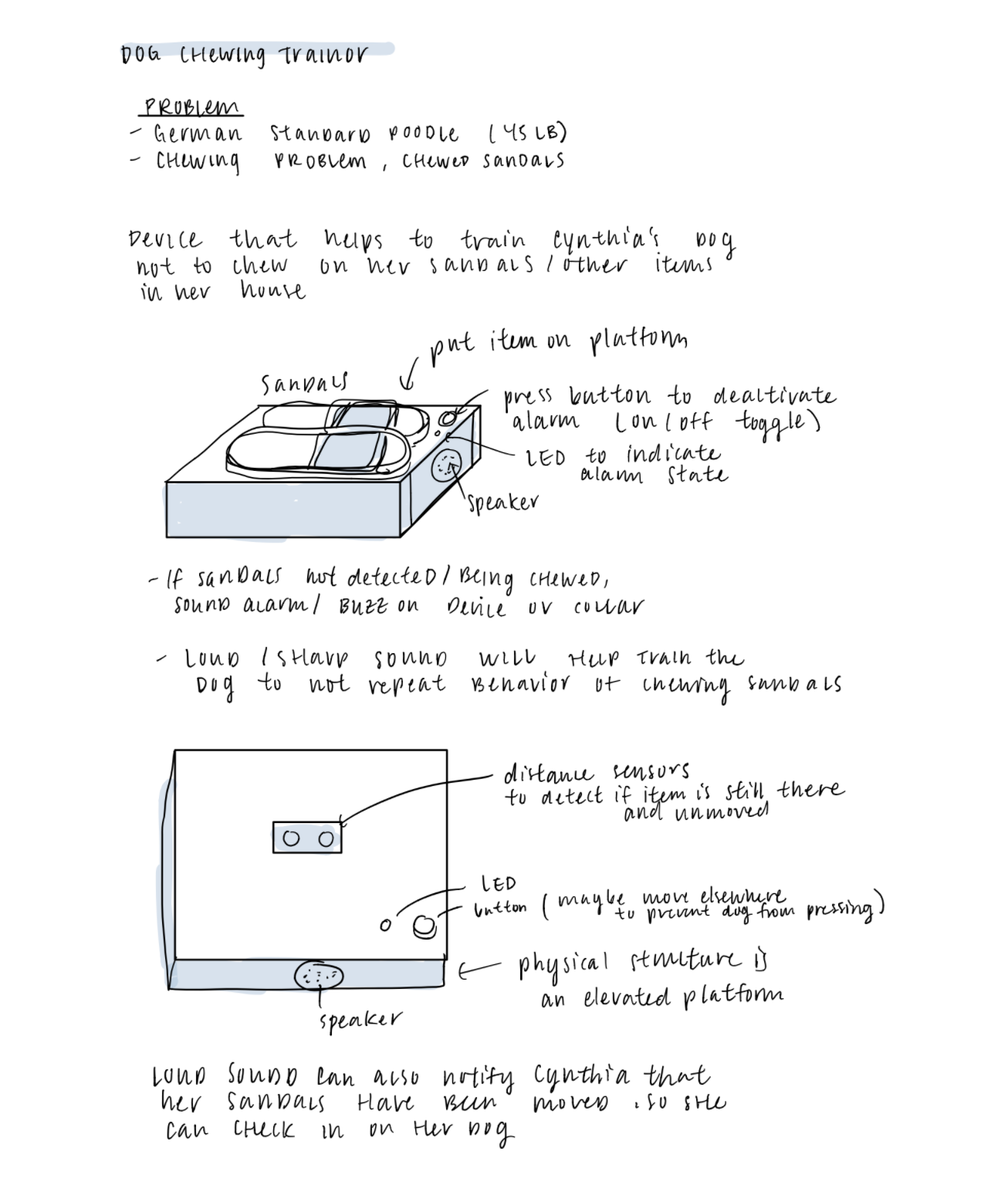
For this project, our team was tasked with creating an assistive device for our Osher student Cynthia. The goal was to design a piece of technology to help her in her daily life. We conducted an interview with Cynthia to gain better insight into her life and identify potential problems we could address with our project. Our team decided to design an automated dog trainer to help train Cynthia’s dog Zimi to stop chewing on her sandals and other valuables. We documented our prototypes before moving onto designing our final device.
What We Built
Our device is a dog trainer that senses the presence of an object placed on top of it. If the device senses the object has been moved, alerting that Zimi is chewing on the object, it will trigger a high pitched alarm sound as punishment. The sound is at a frequency that dogs can hear, so as to not disturb Cynthia. There is an additional switch that can turn the alarm on and off to allow Cynthia to remove the object without sounding off the alarm. Other features include a blue light that turns on to indicate the alarm going off, as well as a separate alarm that goes off at 8am to remind Cynthia to take Zimi outside. Over time, the goal of the device is to train Cynthia’s dog to learn what items he should not be chewing on.
FINAL RenderingS
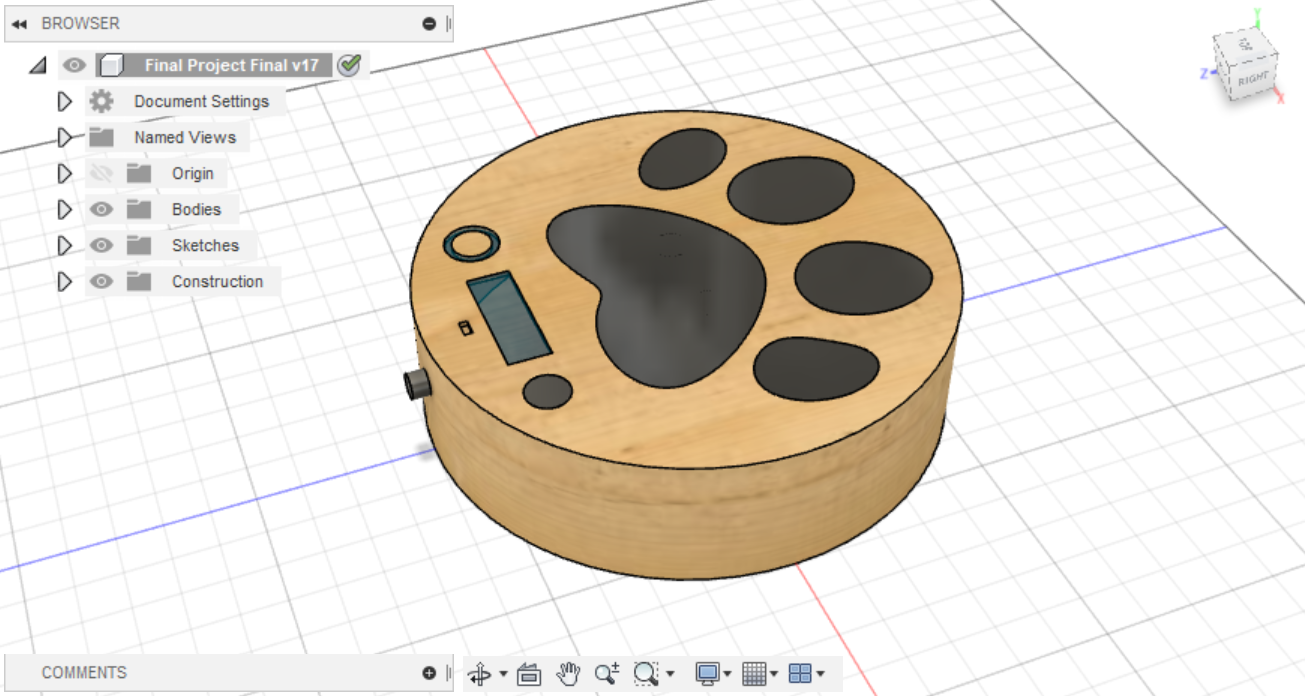
Labeled components of our device modeled with Fusion 360 .
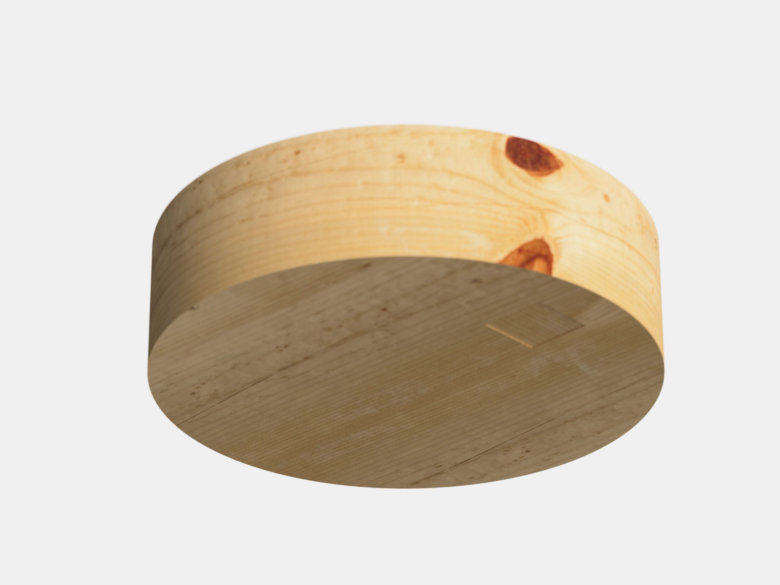
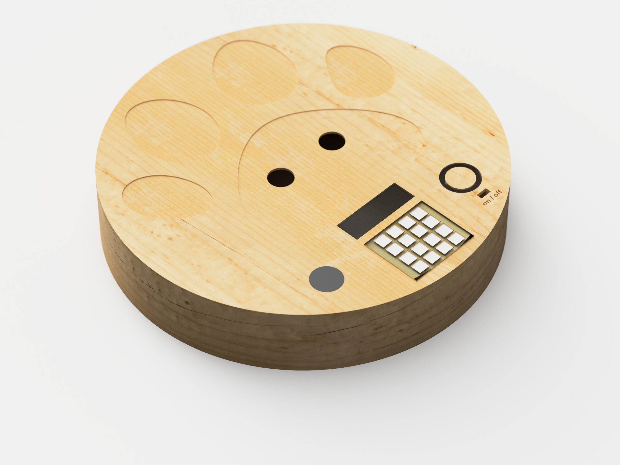
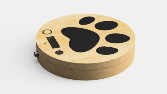
Overall view of the device: A circular, elevated platform with a wooden base and black glass for the paw print detail.
Detailed view of the device components. The keypad is used to input time and alarm sound settings. The LCD screen displays device modes and user inputs.
Battery door located at bottom of device that can be unscrewed to replace battery power.
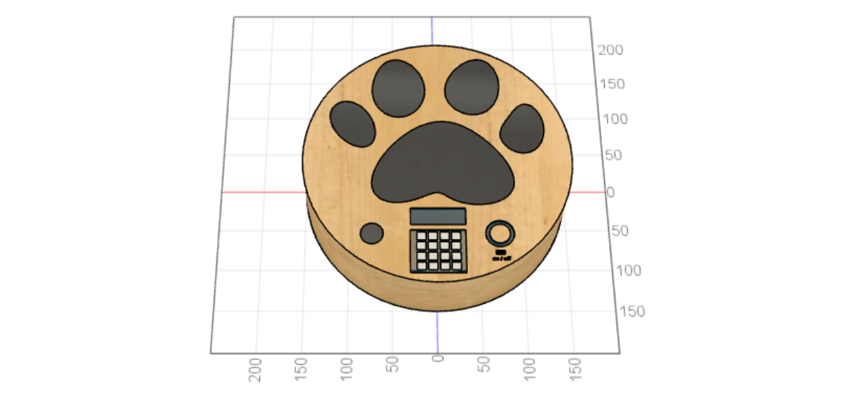
Device measurements for scale (mm)
PIR sensors located beneath the black glass. There is a lower surface panel to hold components.
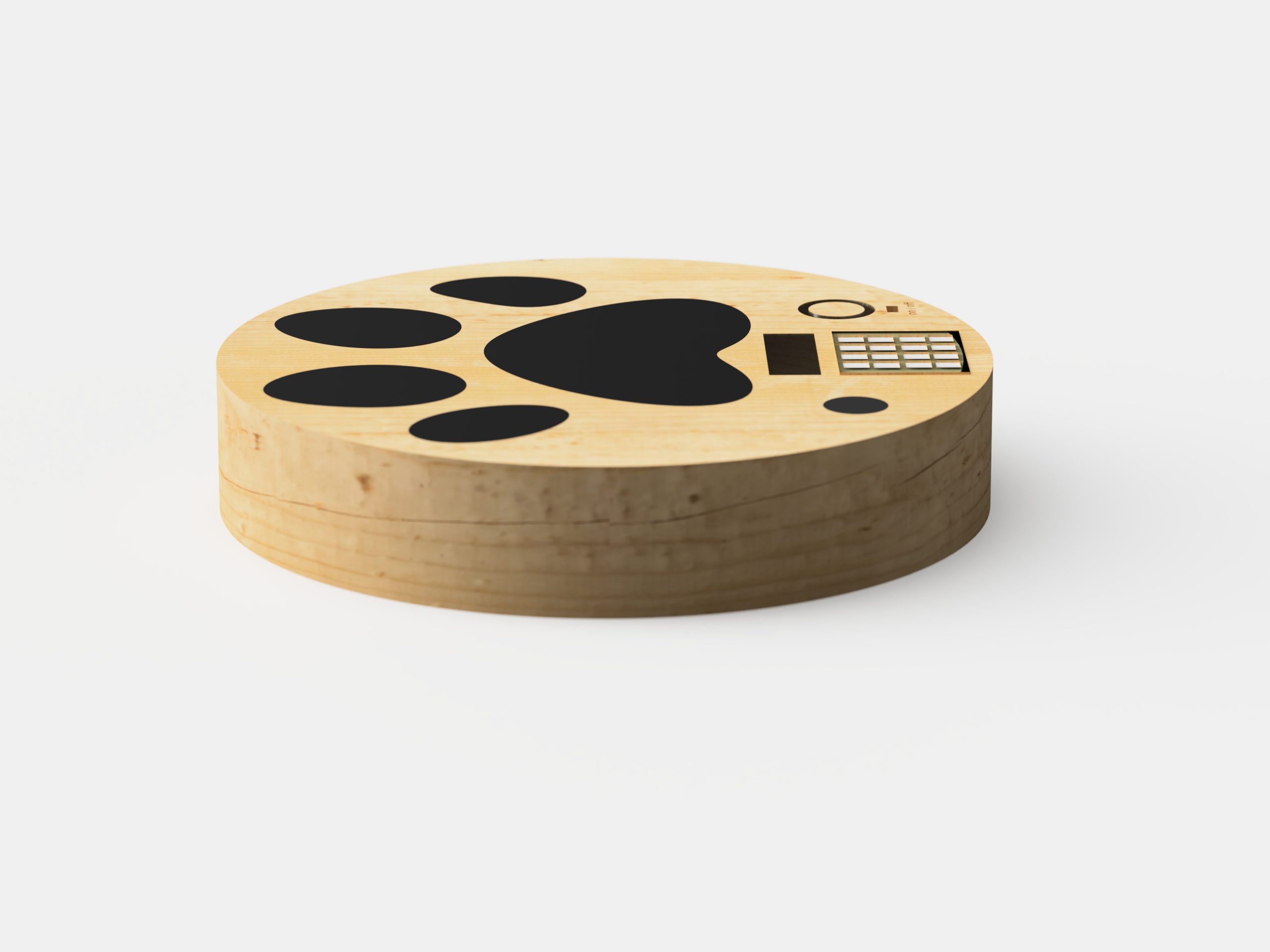
Side view of the device.
TinkerCad INTERACTION
Narrative Sketch
Cynthia is in her kitchen working on her book. Meanwhile, Zimi is walking around the house looking for something to chew on. She sees paper on the platform, her new favorite object to chew on. Zimi walks over and grabs the paper. Suddenly, Zimi hears dog whistles coming from the device. She runs away and the whistling stops. Zimi tries again and the same sound goes off. She gives up and looks for other things to do.
The next morning, Cynthia is eating her breakfast. At 8AM, she hears the device going off and sees the LCD message reminding her to walk Zimi. It was too loud of a sound in the morning, so she turns down the volume. She turns off the alarm, finishes her breakfast, and brings Zimi outside.
In the afternoon, Cynthia resumes in editing her book. One of her papers fell to the ground without her realizing it. Zimi sees the paper, but decides not to bother with it.
How We Got Here
The process of creating this device was definitely a learning experience for us as we had to overcome various challenges along the way. The initial sketch for the device gave us a solid starting point to work off of, but we later made significant changes to the design for both aesthetic and functional purposes. We cycled through iterations of the device, adding new components such as an 8am alarm and volume adjustment after receiving feedback from Cynthia. In our work plan, we scheduled to front load most of the work, which meant finishing the circuits and model renderings within a week. However, we ended up diverging from our original schedule due to last minute revisions.
Initial concept sketches.
One major setback was that TinkerCad doesn’t have the Real Time Clock part, so we had to improvise by creating an alternate means of tracking time through a keypad as the user interface to set the time and then having the device calculate current time from that input. As a result, we got rid of the potentiometer which we initially planned to have control volume since we could just incorporate volume settings onto the keypad.
These changes to the circuit also meant changes to the physical model design. This posed another challenge since we did not anticipate these changes and had to consider ways to add this new keypad component which was quite large and clunky in appearance. We considered adding a separate platform to fit the keypad, but it was not as clean design-wise. In the end, we resized and rearranged the new components to all fit on the top surface which ended up looking alright.
Added potentiometer to adjust alarm volume which was later replaced with keypad .
Rendering the models was time-consuming due to the fact that the renders were made too soon without accounting for last minute changes which required re-rendering. In addition, the quality of the renderings were turning out blurry, and it was only until much later that we discovered it was because the image dimensions were set to very small values, making them pixelated. After increasing image size to 3840px by 2160px, the quality improved dramatically, and we were finally able to get decent renderings of the finished device.
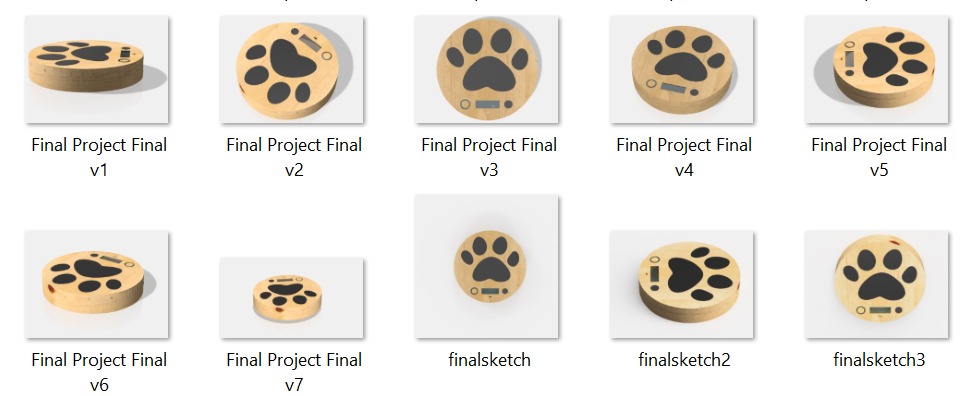
Exported cloud renderings which had to be re-rendered to match updated design.
Blurry rendering of unfinished model.
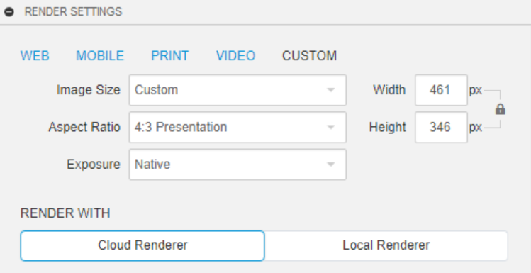
Render settings menu with the default image width and height set to a small pixel size.
Conclusion
We received a mix of feedback during the presentation of our final device. Overall, people liked the aesthetics of our project and the concept behind it. However, some expressed concerns if this form of positive punishment will be successful in real life, which was also a concern we had while developing the device. We mainly worked based on a theory and ran with it, but understood that such a device would have to be tested on Zimi to see if it will actually be useful, though such testing would take a while to get any conclusive results since our device hopes to affect behavior. Others had more specific concerns such as:
Is the alarm for Cynthia with the unit? Would she be able to hear it if it is placed on top of her shoe?
Would this only work for 1 pair of shoes? Would Cynthia need multiple of the devices? For all her shoes?
In regards to the audibility issue, we positioned the speaker away from the middle of the device and in the corner with all of the other electronic inputs/outputs such as the keypad and LED. The device was built large enough that this area would not be covered by a shoe for example. Additionally, Cynthia wanted the ability to change the volume of the device so she can increase/decrease the volume depending on what room she places the device in so she can reasonably hear it. But, we agreed that we can continue to optimize the positioning of the speaker on the device and even the type of speaker. A lot of the feedback was concerned on the practicality of the device’s application with a shoe. We used shoes as an example of what Zimi likes to chew on, but we hope that this device has the versatility to train Zimi not to chew on a variety of small objects. Ideally, we hope Zimi will associate the objects placed on the device with punishment and bad things she should not be chewing on.
After our first prototype, Cynthia expressed Zimi chewing on shoes was no longer a problem since Cynthia decided to hide all of her shoes. However, we agreed hiding shoes might not be practical in the long run as we wanted to teach and train Zimi as a more long-lasting solution to her chewing habits. Cynthia expressed concerns that Zimi is starting to chew on paper she finds on the floor. If our device was built, we would first try it with paper and see how her behavior changes. If successful and Zimi finds other things to chew, then we would potentially put whatever new object Zimi likes to chew onto the device so that we can prime her not to chew on those types of items.
Collaborating and developing a device remotely had its challenges. Due to online learning, we shifted to using mainly CAD and TinkerCad to develop and present our work. A lot of the project work was split into individual tasks which we worked separately on. Some tasks were more difficult to collaborate on remotely, for instance creating the CAD model or wiring the circuit. This task allocation actually turned out to work pretty well since we were able to concentrate on our own side of the project. In the end, although we each addressed separate project domains, we were able to create a cohesive device by combining our components.
Reflecting on the process of building this device, one of the biggest challenges was using TinkerCad, which is slow, has limited parts, and definitely buggy. For instance, we originally wanted to use an IR remote instead of a keypad. However, the library for the IR remote could not be added to the code without creating errors. Additionally, simulating the interaction is not the same as real life. The project would have definitely been easier and more constructive if we have the electronic parts with us to physically troubleshoot challenges in the wiring and code. If we were to do the project again, we would like to do this part of the project physically in real life, so that we can have a better understanding of the functionality of the device and better improve it.
The CAD portion also had it has its own challenges, but in the end improved the quality of the overall project. For future CAD models, we learned it’s important to leave room for error and design adjustment before moving onto final rendering. We would have had to use CAD anyway, but since we didn’t have to fabricate it, it expanded the potential of the overall physical device. Our specific device can be fabricated, but the situation allowed us to design more complex designs without being held back by fabrication difficulties.
Working with an older person and designing a device specifically for them was a new experience for us. We thought it was a wonderful experience learning about Cynthia during our initial interview with her. She has lived in Pittsburgh for a long time so she was able to share some insights about her favorite places to eat and drink. One of the major takeaways that became apparently clear especially after the final presentations were that many of the devices built address issues that many people people might have problems with and have the potential to reach a wider population.
Technical Details
TINKERCAD
TinkerCAD (https://www.tinkercad.com/things/91w05kUAJCs)
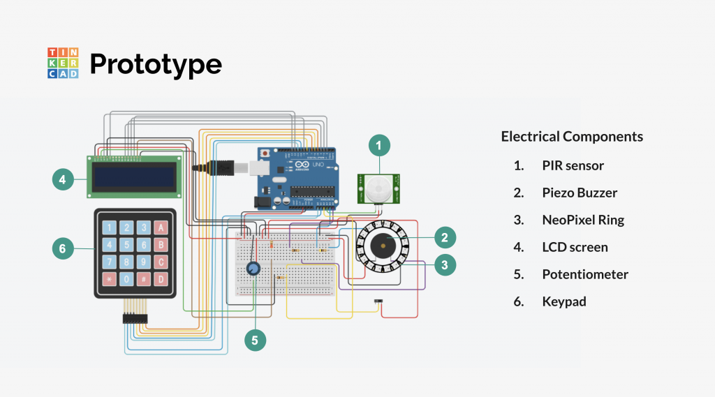
Breadboard image of Tinkercad model
Code
#include <Adafruit_NeoPixel.h>
#include <Keypad.h>
#include <LiquidCrystal.h>

/**
   Title: Dog Trainer
   Author: Gracia Genero
   Description: This code controls the components listed below.
   It fires Zimi's alarm through the speaker/LED when motion is detected
   through the PIR Sensor. The PIR sensor and Zimi's alarm can be deactivated
   by flipping the switch. Additionally, this device keeps track of time'
   time, but requires the user to input a current military time to do so accurately.
   At 8AM a separate alarm goes off to remind the user (Cynthia) to walk her dog
   Zimi. This alarm can be turned off through the keypad input. The volume of
   Cynthia's alarm can also be adjusted through the keypad. The LCD screen displays messages
   when the alarm is activated or when an input is in progress of being typed into the
   keypad. Otherwise, it displays the calculated current time and volume.


   Pin mapping:

   pin        | mode   | description
  ------------|--------|------------------------------------
   A3         | input  | PIR motion sensor
   A4         | output | NeoPixel Ring 16
   A5         | output | speaker
   A2         | input  | switch
   A0,A1,11,10| input  | keypad - row pins
   8,7,6,5    | input  | keypad - column pins
   4,3,9,2    | input  | LCD - DB4-DB7
   13         | input  | LCD - register select pin
   12         | input  | LCD - enable pin


  Credits:
  https://www.tinkercad.com/things/ascn1ro2gFR-lcd-display
  https://www.tinkercad.com/things/jLFSyDIIEpj-pir-motion-sensor-with-arduino-blocks
  https://www.tinkercad.com/things/k4BAT8c26NN-print-4x4-keypad-input-to-lcd


 **/

const int SPEAKERPIN = A5;
const int SWITCHPIN = A2;
const int LEDPIN = A4;
const int LEDCOUNT = 16;       // number of NeoPixels in series
const int PIRPIN = A3;
int pirState = LOW;             // we start, assuming no motion detected
int pirVal = 0;                 // variable for reading the pin status
int ledState = LOW;
int piezState = LOW;
String vol = "5"; // range 0-9
String setTime = "0500";
String keypadInput = "";
String alarmTime = "0800";
String currentTime = "0500";
int CynthiaAlarm = 0;
int turnedOff = 0;

int editMode = 0;
int volMode = 0;
unsigned long int setMillis= 0;
int LCDCol = 0;

const byte ROWS = 4; //four rows
const byte COLS = 4; //three columns
char keys[ROWS][COLS] = {
  {'1','2','3','A'},
  {'4','5','6','B'},
  {'7','8','9','C'},
  {'*','0','#','D'}
};
byte rowPins[ROWS] = {A0, A1, 11, 10}; //connect to the row pinouts of the keypad
byte colPins[COLS] = {8, 7, 6, 5}; //connect to the column pinouts of the keypad
Keypad keypad = Keypad( makeKeymap(keys), rowPins, colPins, ROWS, COLS );

// Object
Adafruit_NeoPixel rgb(LEDCOUNT, LEDPIN, NEO_RGB + NEO_KHZ800);
LiquidCrystal lcd(13, 12, 4, 3, 9, 2);


void setup() {
  pinMode(SWITCHPIN, INPUT);
  pinMode(LEDPIN, OUTPUT);      // declare LED as output
  pinMode(PIRPIN, INPUT);     // declare sensor as input
  pinMode(SPEAKERPIN, OUTPUT);

  lcd.begin(16, 2);
  Serial.begin(9600);

}

void loop(){

  char key = keypad.getKey();
  if (key){
    Serial.println(key);

    if (key == '*') {
    setTime = keypadInput;
    setMillis = millis();
    Serial.println("Set time = " + String(setTime) + " at millis "+ String(setMillis));
    editMode = 0;
    keypadInput = "";
    Serial.println("Time Set");
    LCDCol = 0;
    lcd.clear();
    }

    if (editMode == 1) {
      keypadInput += String(key);
      lcd.setCursor(LCDCol, 1);
      lcd.print(key);
      LCDCol += 1;
    }

    if (volMode == 1) {
      vol = String(key);
      volMode = 0;
       }

    if (key == 'A') {
      editMode = 1;
      Serial.println("Setting Current Time");
      lcd.clear();
      lcd.setCursor(0,0);
      lcd.print("Set current time");

    }

    if (key == 'B') {
      volMode = 1;
      Serial.println("Changing Volume");
      lcd.clear();
      lcd.setCursor(0,0);
      lcd.print("Set volume");
    }
  }

  Serial.println("Volume = " + vol);

  // Calculates current time based on last current time by the user
  int deltaMin = ((millis() - setMillis) / 60000) % 60;
  int deltaHour = ((millis() - setMillis) / 60000) / 60;

  String setMin = setTime.substring(2);
  int min = setMin.toInt();
  String setHour = setTime.substring(0,2);
  int hour = setHour.toInt();

  int newMin = (min + deltaMin) % 60;
  String newMinStr = String(newMin);
  if (((newMin % 10) >= 0) and ((newMin / 10) < 1)) {
  	newMinStr = "0" + newMinStr;
  }
  if (((min + deltaMin) / 60) >= 1) { deltaHour += 1; }
  int newHr = (hour + deltaHour) % 24;
  String newHrStr = String(newHr);
  if (((newHr % 10) >= 0) and ((newHr / 10) < 1)) {
  	newHrStr = "0" + newHrStr;
  }
  currentTime = newHrStr + newMinStr;
  Serial.println("SetTime = " + setTime + ", Current Time = " + currentTime);

  if (((editMode == 0) and (volMode == 0)) and (CynthiaAlarm == 0)) {
      lcd.setCursor(0, 0);
      lcd.print("Time: " + currentTime);
      lcd.setCursor(0, 1);
      lcd.print("Volume: " + vol);
    }

  int switchState = digitalRead(SWITCHPIN);
  pirVal = digitalRead(PIRPIN);  // read input value
  Serial.println("PIRSensor = " + String(pirVal));

  if ((currentTime == alarmTime) and (turnedOff == 0)) {
    CynthiaAlarm = 1;
    }
  if (currentTime.toInt() >= 803) {
    CynthiaAlarm = 0;
    turnedOff = 0;
    lcd.clear();
  }
  if ((key == 'C') and (currentTime.toInt() <= 803) and (currentTime.toInt() >= 800)) {
  	turnedOff = 1;
    CynthiaAlarm = 0;
    lcd.clear();
  }
  if (CynthiaAlarm == 1) {
      tone(SPEAKERPIN, 100);
      lcd.clear();
      lcd.print("It's time for");
      lcd.setCursor(0,1);
      lcd.print("a walk!");
  }
  else {
  if (switchState == LOW) {
  if (pirVal == HIGH) {          // check if the input is HIGH
    // turn on LED blue
    for(int i=0; i<rgb.numPixels(); i++) {
    rgb.setPixelColor(i, 0, 0, 150);    // sets the RGB values for pixel number i
    // rgb.show();
    }
    rgb.show();
    analogWrite(SPEAKERPIN, vol.toInt()*14); // sets duty cycle or volume of piezo buzzer
    tone(SPEAKERPIN, 25000); // speaker sends off sound frequencies only dogs can hear
    if (pirState == LOW) {
      Serial.println("Motion detected");
      pirState = HIGH;
    }
  }
  else {
    noTone(SPEAKERPIN); // turns off speaker
    rgb.clear(); // turn off LED
    rgb.show();
    if (pirState == HIGH){
      Serial.println("Motion ended");
      pirState = LOW;
    }

  }
  }

  else {

  noTone(SPEAKERPIN);
  rgb.clear(); // turn off LED
  rgb.show();
  }
  }
}
SCHEMATIC
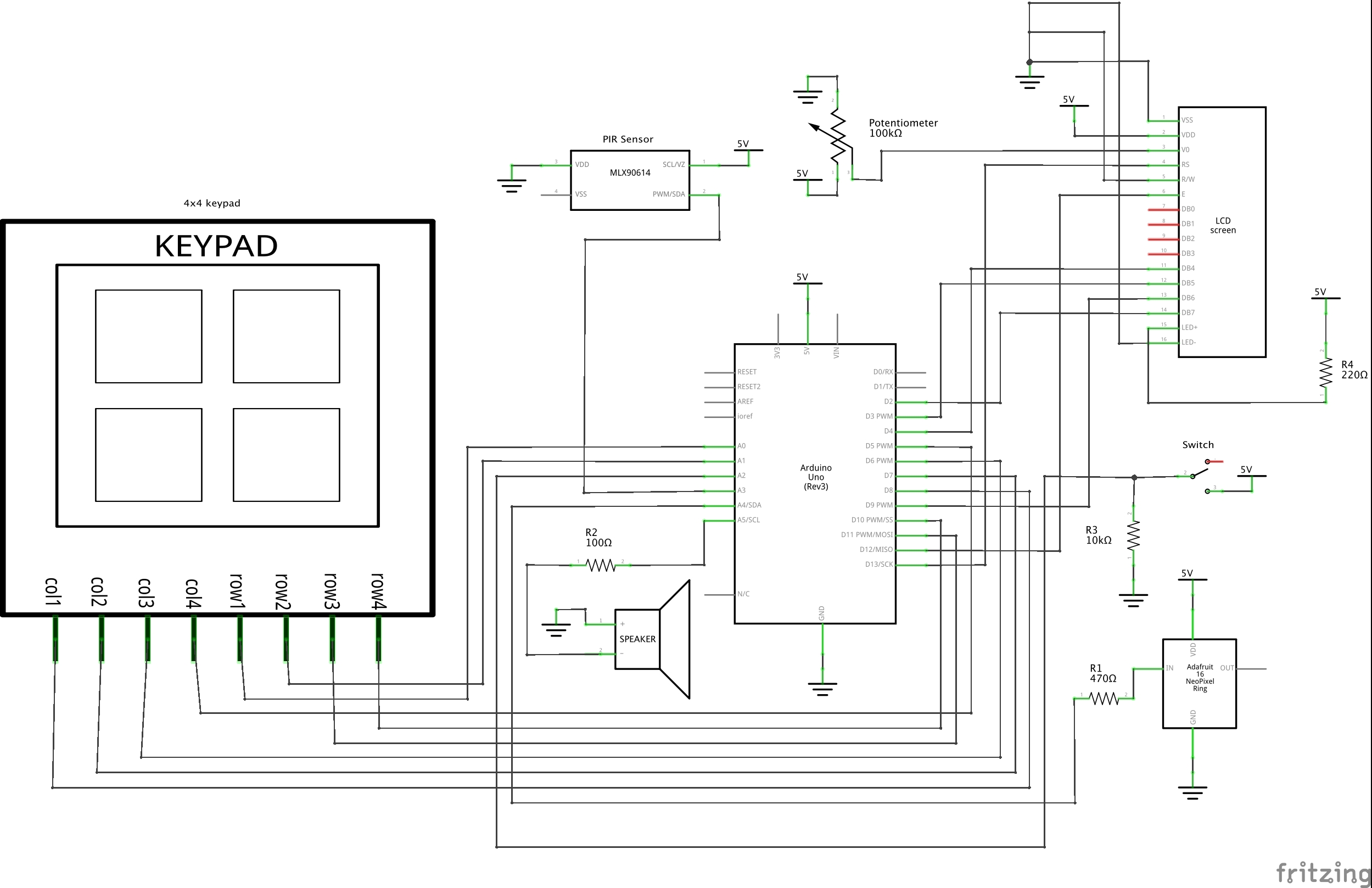
Schematic of dog trainer device
Comments are closed.