Project description
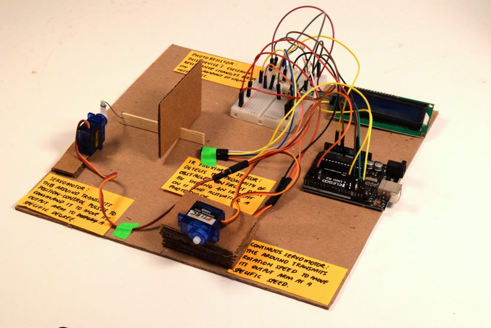
A 10’’ by 10’’ cardboard has a light sensor on the top side. When the light goes from dim to bright, a blue motor on the left side pushes the Popsicle stick to the right. As the Popsicle stick gets closer to the distance sensor, the servo motor on the bottom spins faster.
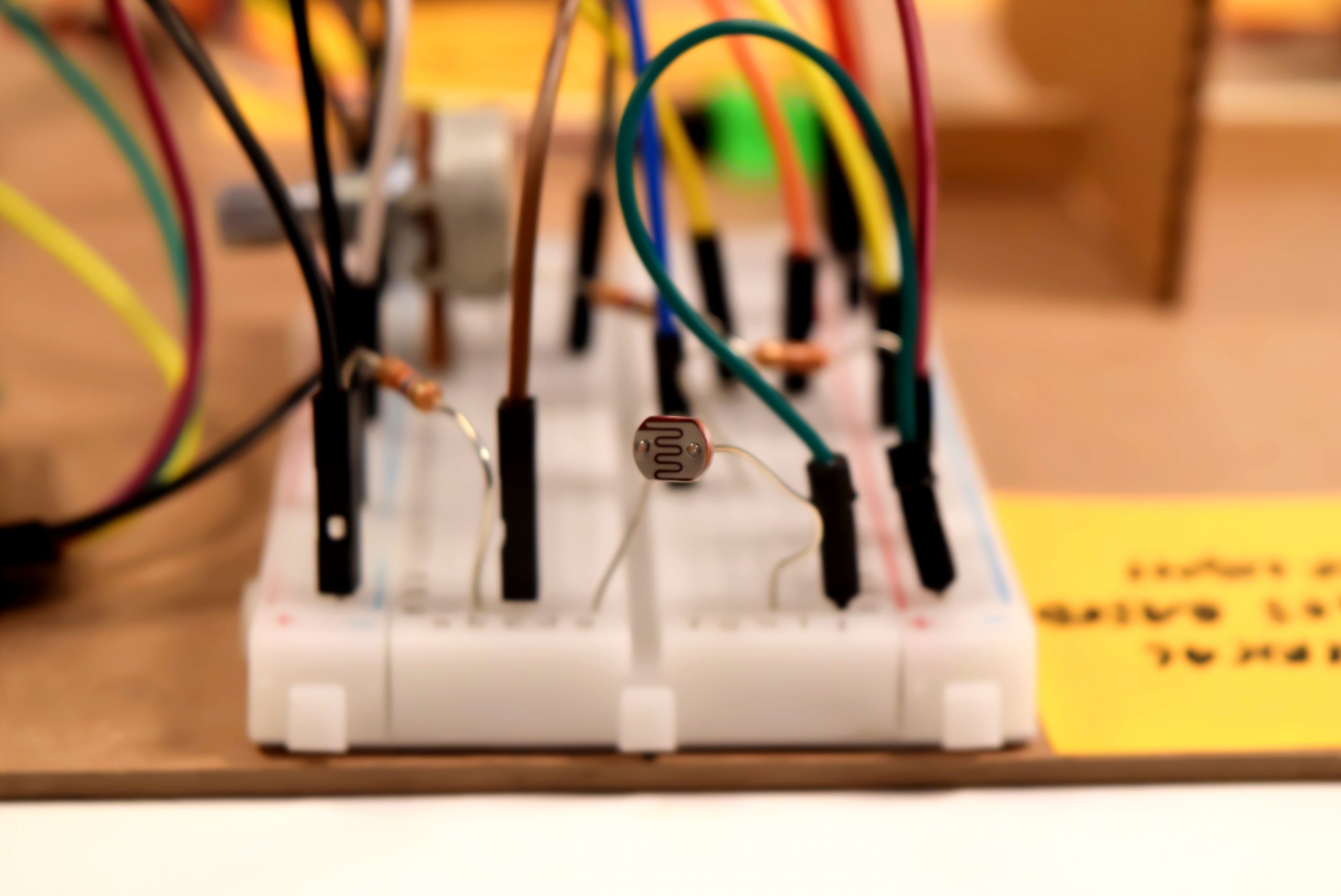
Input sensor: Photoresistor detects light brightness
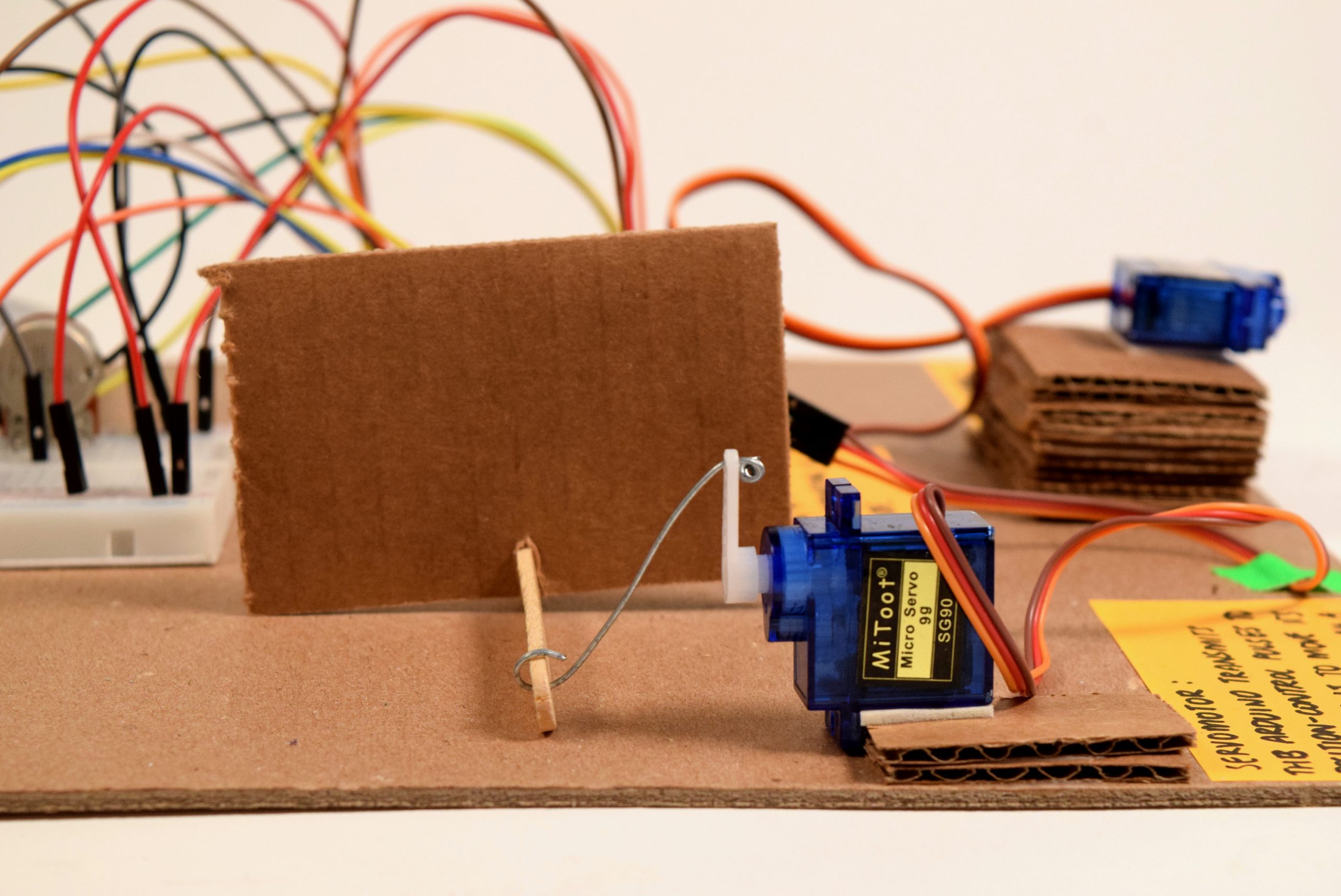
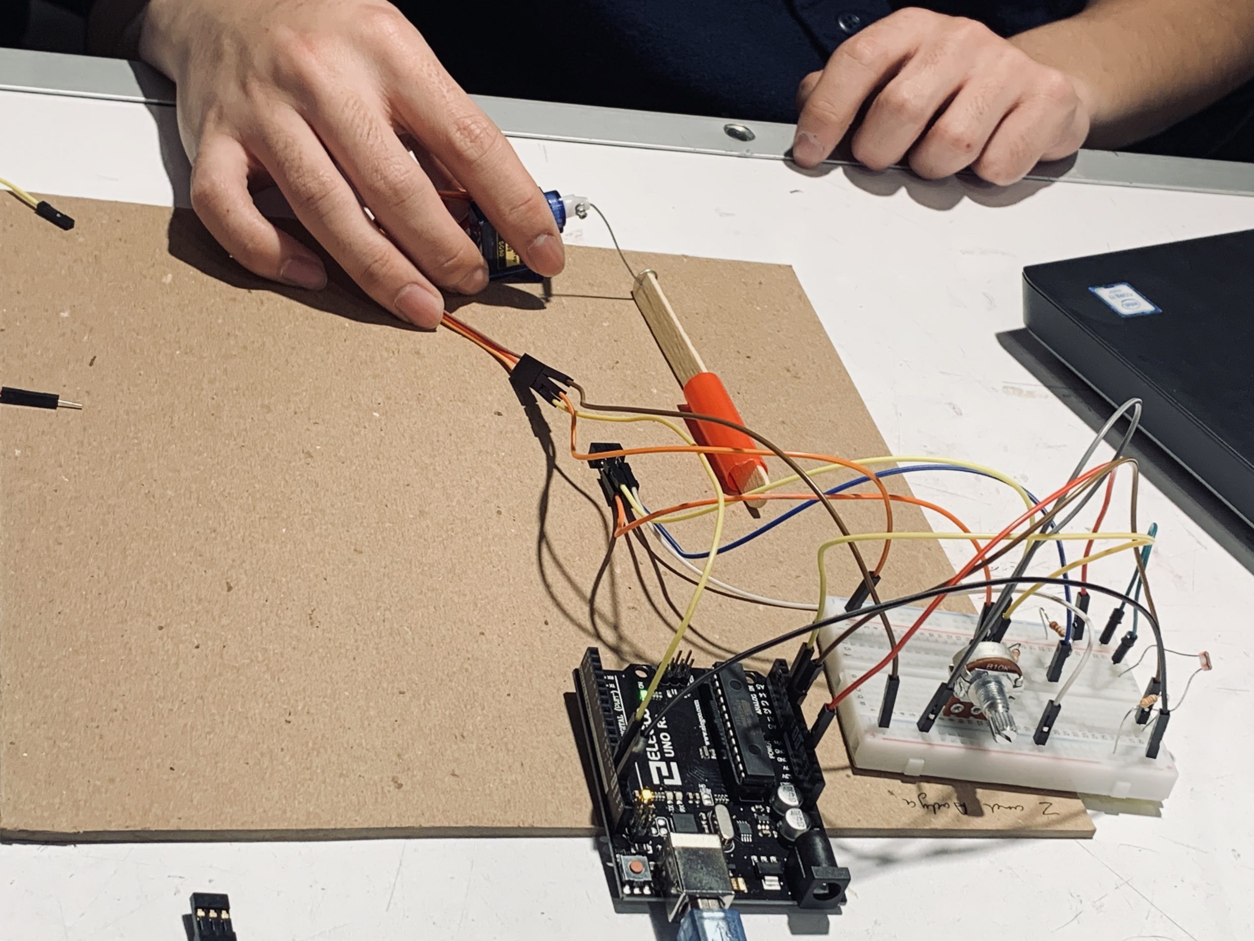
Middle actuator: Servo motor drives linear actuation
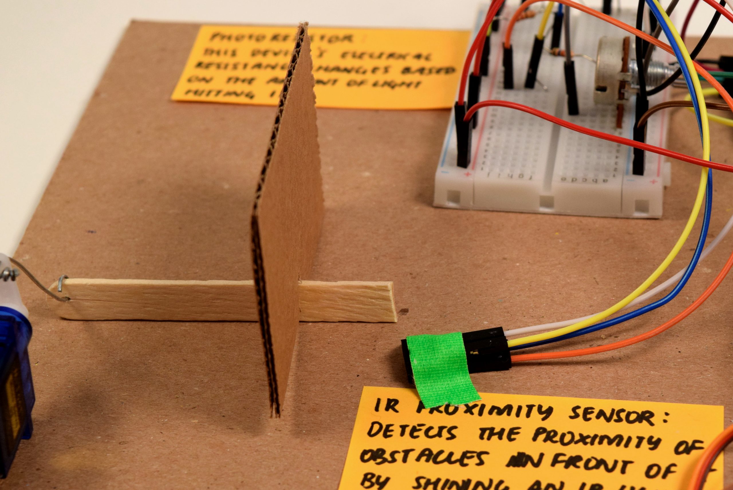
Middle sensor: IR proximity sensor reads linear actuation
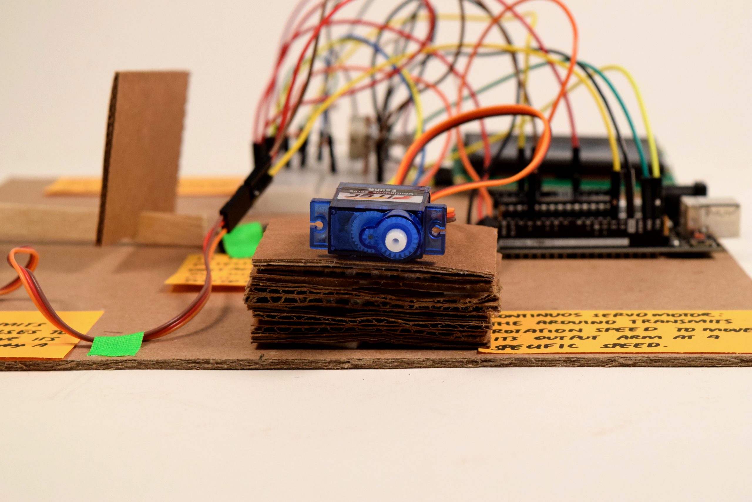
Output actuator: Continuous servo motor
Process
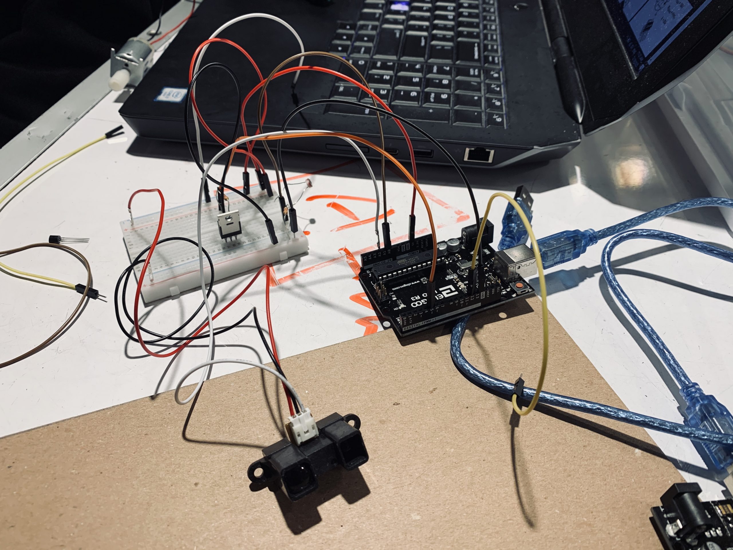
Testing the accuracy of one specific type of IR sensor.

Bending the metal arm to create linear motion
Testing to see if a plastic straw help to stabilize the motion of the popsicle
Discussion
This project was an excellent experience for us to learn new skills and gain confidence in creating interactive computing projects. The process of ideating helped us think of creative ways to transmit energy. We were initially interested in converting the light brightness to vibration intensity, which would ultimately manifest as rotation speed. However, after our initial check-in, we realized that having linear movement as the middle step instead of the vibration intensity would produce a stronger and more foolproof signal, as we later saw on demo day.
Throughout the project, we were fascinated by the idea of converting one form of energy into a seemingly unrelated form. When the project was introduced to us, we were very intrigued by the thought of turning light brightness to rotation speed. This fascination didn’t stop there. Something as simple as using a servo motor to produce linear movement using very simple materials from the physical computing lab was exciting.
Overall we were proud of how our project turned out. On demo day, one of the guest critics commented on our use of two servo motors in very different ways to produce various kinds of motion. That helped to crystallize the diverse applications of the components that were available to us in the lab and the endless possibilities with them!
Schematic
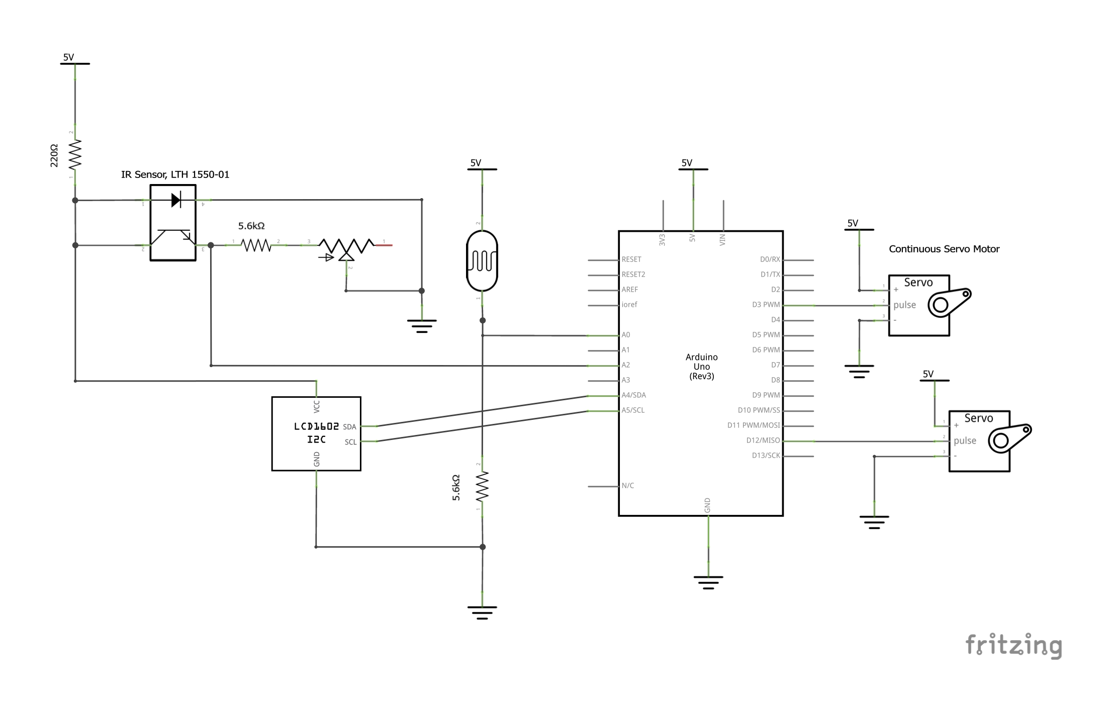
Schematic
Code
/*
  Project title: lightSpin

  Description: The following code direct the arduino to read values from a photoresistor and an IR proximity sensor,
  and manipulate a servo motor and a continuous servo motor accordingly.The value given by the photoresistor is mapped
  to a range of degree (0-180) that the servo motor turn to. The value given by the IR proximity sensor is mapped to a
  range of rotation speed for the continuous servo motor. Finally, the working percentages of each input and output are
  displayed on a LCD screen in a range of 0-99.

  Pin mapping:

   pin   | mode   | description
   ------|--------|------------
   3      output    Determines the rotation speed of the continuous servo motor
   7      input     Turns on the flashlight
   12     output    Turns the servo motor to different degree (0-180)
   A0     input     For the photoresistor to detect the light intensity
   A2     input     For the IR proximity sensor to detect the linear distance  to the popsicle
   A4     output    Serial data; for communication to the LCD screen
   A5     output    Serial clock; for communication to the LCD screen

  Credit:
  When wiring the circuit for the IR sensor we have refered to the tutorial on the class webpage to set up the potentiometer.
  In addition, the tutorial of the LCD was also used. The function 'lcd' was written under the help of Esteven.

*/

//include the library for LCD and servo motor
#include <Servo.h>
#include <Wire.h>
#include <LiquidCrystal_I2C.h>

//Setting up the constants for pins and the variables
const int photoPin = A0;
int brightness;
const int servopin = 12;
int servoTurn;
const int proxPin = A2;
int distance;
const int motorPin = 3;
int rotaSpeed;
int rerangedBrightness;
int rerangedServoTurn;
int rerangedDistance;
int rerangedRotaSpeed;
int counter = 0; // variable to use for periodic updates
const int FREQ = 20; // number of loop()s to run before update


/* Create an LCD display object called "screen" with I2C address 0x27
   which is 16 columns wide and 2 rows tall. You can use any name you'd like. */
LiquidCrystal_I2C screen(0x27, 16, 2);


/* Definition of a custom character called "frowny" which will be used later.
   Each digit is a pixel of the 5x7 array that forms a single character on this display.
   Draw your own at https://maxpromer.github.io/LCD-Character-Creator/ */
byte frowny[] = {
  B00000,
  B11011,
  B11011,
  B00000,
  B00000,
  B01110,
  B10001,
  B00000
}; // (note the extra row of zeros at the bottom)


//Nme the two servo motors
Servo smallMotor;
Servo bigMotor;

/*This function "write" the four elements onto the LCD screen. This is crucial as
  it sloves the porblem of incorrect numbers popping up when the values are 3 digits*/
void lcd(LiquidCrystal_I2C screen, int input, int m1, int m2, int output) {
  // set cursor to home position, i.e. the upper left corner
  screen.setCursor(0, 0);
  // print the input sensor value
  screen.print((String)"i:" + input);

  screen.setCursor(6, 0);
  screen.print((String)"m:" + m2);

  screen.setCursor(8, 1);
  screen.print((String) m2);

  screen.setCursor(12, 1);
  screen.print((String)"o:" + output);
}


void setup() {
  //set up the pins
  pinMode(photoPin, INPUT);
  pinMode(proxPin, INPUT);
  pinMode(motorPin, OUTPUT);

  //set up the servomotor
  smallMotor.attach(servopin);
  bigMotor.attach(motorPin);

  //LCD setup
  screen.init();
  screen.backlight(); // turn on the backlight to start

  //setup the serial feedback
  Serial.begin(9600);
}

void loop() {

  //Sense the brightness of the environment
  brightness = analogRead(photoPin);

  //Turn the servo motor
  servoTurn = map(brightness, 50, 300, 0, 180);
  servoTurn = constrain(servoTurn, 0, 180);
  smallMotor.write(servoTurn);

  //Sense the distance of the popsicle
  distance = analogRead(proxPin);


  //determine the rotation speed
  rotaSpeed = map(distance, 200, 350, 90, 0);
  rotaSpeed = constrain(rotaSpeed, 0, 90);
  bigMotor.write(rotaSpeed);

  //values are reranged so that they are displayed as 0-99 on the LCD
  rerangedBrightness = map(brightness, 50, 300, 0, 99);
  rerangedServoTurn = map(servoTurn, 0, 180, 0, 99);
  rerangedDistance = map(distance, 200, 350, 0, 99);
  rerangedRotaSpeed = map(rotaSpeed, 90, 0, 0, 99);

  rerangedBrightness = constrain(rerangedBrightness, 0, 99);
  rerangedServoTurn = constrain(rerangedServoTurn, 0, 99);
  rerangedDistance = constrain(rerangedDistance, 0, 99);
  rerangedRotaSpeed = constrain(rerangedRotaSpeed, 0, 99);


  //show the current vlaues of the inputs and outputs; for testing
  Serial.println((String)"brightness " + brightness + " servoturn " + servoTurn + " distance " + distance + " rotaspeed " + rotaSpeed + " " + rerangedRotaSpeed   );

  // running a periodic non-blocking task
  if (counter >= FREQ) { // if counter meets or exceeds FREQ

    lcd(screen, rerangedBrightness, rerangedServoTurn, rerangedDistance, rerangedRotaSpeed);


    counter = 0; // and reset counter
  }
  counter++; // increment counter every loop cycle

}
Comments are closed.