Project Title
Double Transducer
Video and Photos

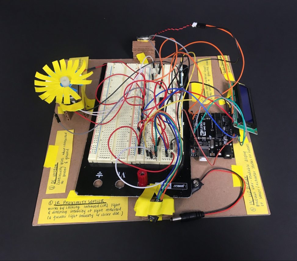
Our completed double transducer with labels.
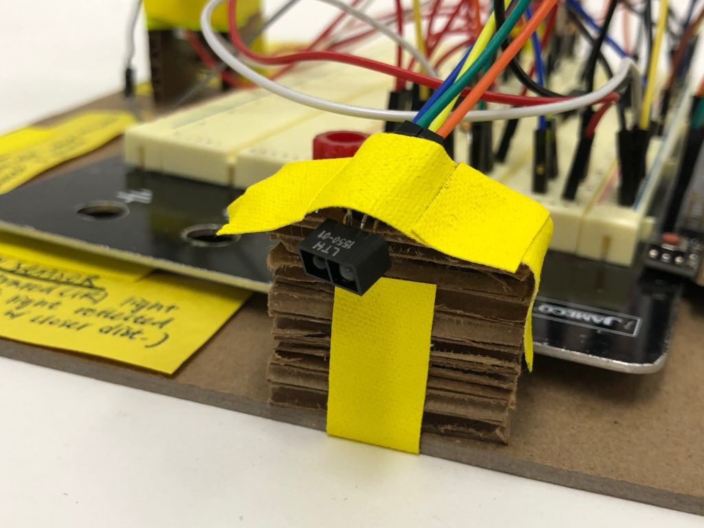
Input IR sensor to detect linear distance.
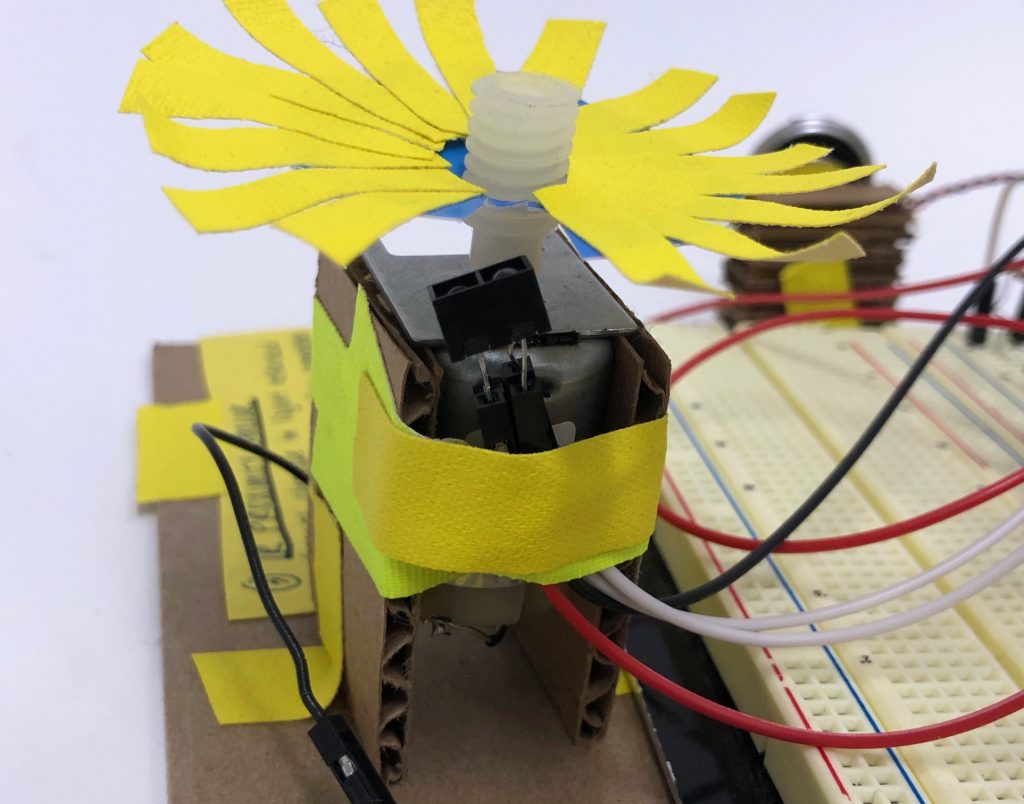
DC motor with IR sensor below to detect fan rotation speed.
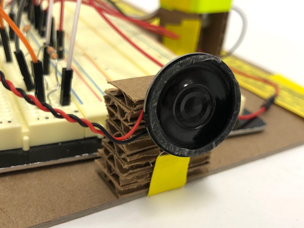
Output speaker to produce pitch at different sound volumes.
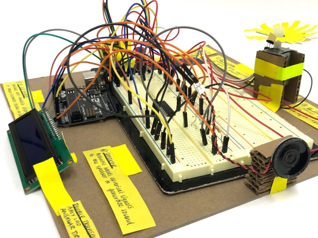
Overall physical layout of our model.
Simple Narrative Description
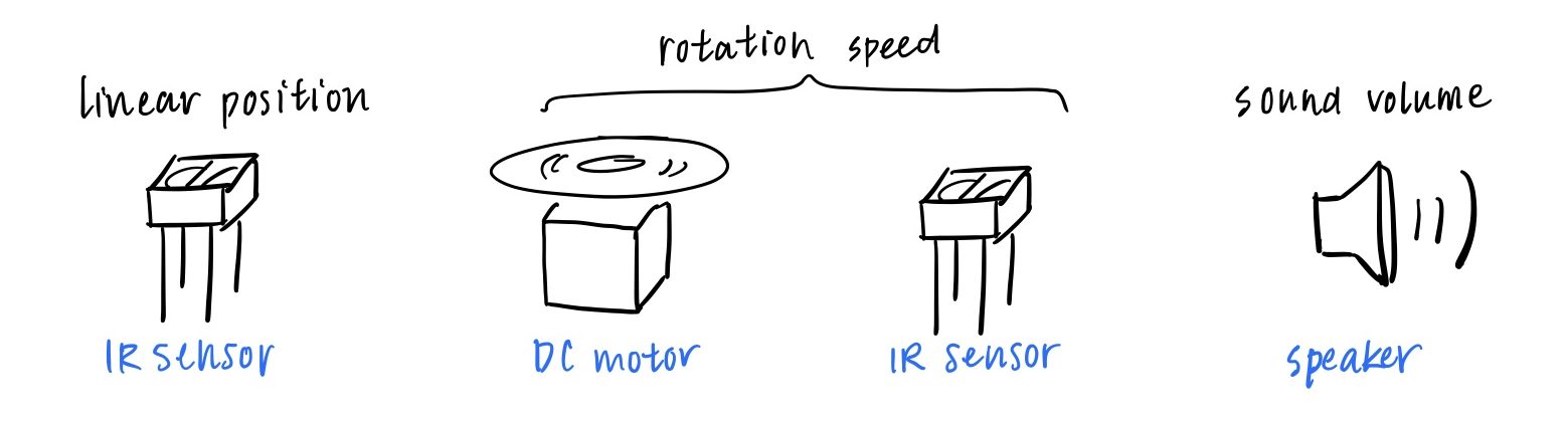
There is a sensor on the side that tells a motor to start spinning faster once it detects when something is moving closer towards it. Another sensor reads in the speed of the motor’s rotation and tells a speaker to decrease its volume in response to faster rotation.
Progress Photos
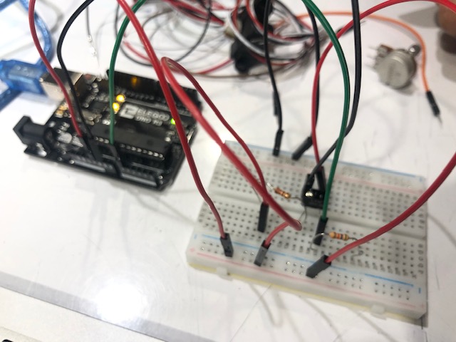
We began by trying to figure out the wiring for the IR photosensor to read in distance values.
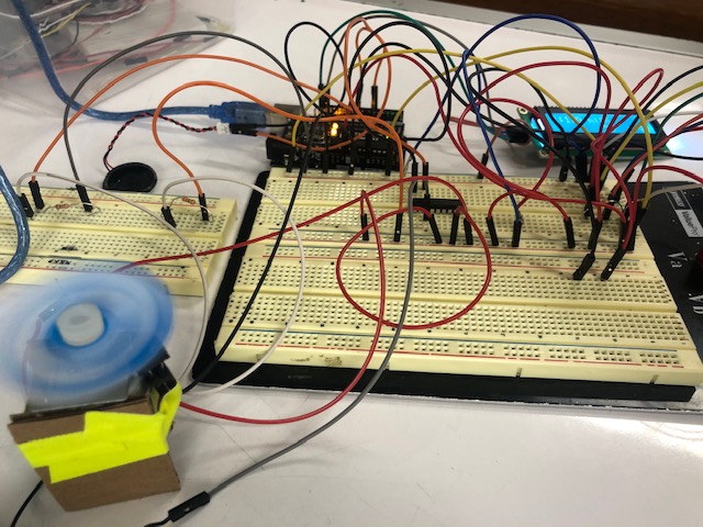
We tested out the DC motor at varying speeds depending on amount of voltage passed through.
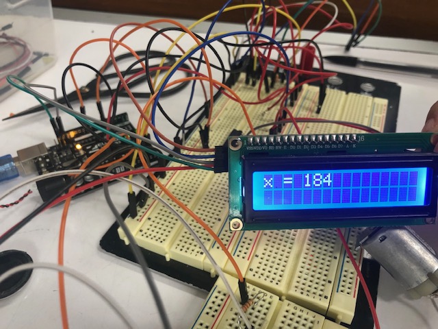
We tested out the LCD display with varying sensor value inputs.
Discussion
To build our project, it was difficult to first approach all these new components we’d never worked with before. This project went through several iterations before we finally settled on our current design. We had considered using rotation angle as our intermediary step since we could use the hobby servo motor, which we were already familiar with. However, in the end we decided to go with rotation speed because although less familiar, it seemed to be a fun challenge.
Surprisingly the smaller mistakes often caused us the most trouble. For a long time we couldn’t figure out why the speaker wasn’t producing noise, and it turned out the speaker pin was just defined as the wrong number. The wiring for the IR proximity sensor also wasn’t working before we realized it was because we were just missing the pull down resistor at the side. For later components, we noted it was important to wire things carefully and pay attention to all the details of a schematic. In addition, mapping the values caused issues because we were giving the incorrect ranges. We realized it would be much easier to tackle this project one component at a time rather than a bit of everything at once as it would help isolate where errors were occurring.
One of the biggest challenges to tackle for this project was figuring out a way to measure rotation speed. Because there was no component which could directly read in speed, we had to get creative with our options. The Internet was mostly a useful resource as there were online tutorials to help us navigate through working with unfamiliar libraries and parts. But in this case, we over complicated things by trying to follow confusing online tachometer tutorials. In the end, we decided it would be better to take our own approach. We used an IR sensor and distance calculations to track rpm. It was a much easier solution as we got to reuse the same component, just repurposed as a tachometer.
For future improvements, we could try cleaning up the appearance of the physical model, and it might be nice to build a container to hide the messy wires. Despite all our setbacks, we were able to put everything together and get a successful transducer working. We learned not to overcomplicate simple tasks and to tackle future projects with the bigger picture in mind. Overall, this project was a good learning experience as we learned how to use new parts and apply creative problem solving.
Schematic 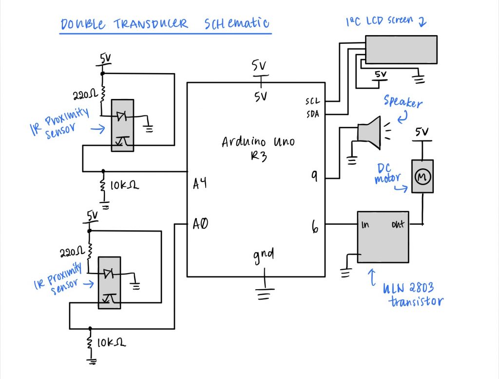
Code Submission
/*
 * Project Title: Double Transducer
 *
 * Description: This code reads change in linear distance through
 * an IR sensor. A motor's fan spins with a faster speed in response
 * to closer distances and a slower speed in response to further
 * distances. Another IR sensor acts as a tachometer by reading in
 * the rotation speed of the fan by tracking # rotations per second.
 * An output speaker's volume decreases in response to faster fan
 * rotation speeds and increases with slower speeds. An LCD screen
 * displays updated status of these sensor & actuator states.
 *
 * Pin mapping:
 *
 * pin   | mode   | description
 * ------|--------|------------
 * A4      input     IR sensor (input)
 * A0      input     IR sensor (tachometer)
 *  9      output    sound speaker pin
 *  6      output    motor pin
 *
 * Credit: Incorporated timer-based periodic update code
 * from the course website:
 * https://courses.ideate.cmu.edu/60-223/s2020/reference/class-log
 *
 */

#include <NewPing.h>
#include <Servo.h>
#include <Wire.h>
#include <LiquidCrystal_I2C.h>
#include "Volume3.h"

#define PHOTOPIN1 A4 // input IR sensor
#define PHOTOPIN2 A0 // rpm measurement IR sensor
#define SPEAKER_PIN 9 // sound speaker
#define MOTORPIN 6 // DC motor pin
#define FREQUENCY 440 // pitch for speaker to play

Servo steeringMotor; // create motor object
LiquidCrystal_I2C screen(0x27, 16, 2); // create LCD display object

unsigned long timer = 0; // variable for timing LCD
unsigned long timer2 = 0; // variable for timing rpm
const int INTERVAL = 500; // milliseconds between LCD updates
const int INTERVAL2 = 1000; // milliseconds between rps updates
uint16_t frequency = 440; // speaker tone frequency

// val to store previous distance in rpm sensor
int photoVal2prev = 0;
int rotations = 0;
int rps = 0; // how many rotations per sec
int lastCycle = 0;

// update display of sensor & actuator states (4-10x per sec)
void updateScreen(int i, int m1, int m2, int o) {
  // map states within 0-99 range
  screen.setCursor(2, 0);
  screen.print(map(i, 500, 800, 0, 99)); // print input
  screen.setCursor(8, 0);
  screen.print(map(m1, 0, 1000, 0, 99)); // print m1
  screen.setCursor(8, 1);
  screen.print(map(m2, 0, 70, 0, 99)); // print m2
  screen.setCursor(14, 1);
  screen.print(map(m2, 0, 90, 0, 99)); // print output
}

void setup() {
  Serial.begin(9600); // open serial monitor at 9600 baud

  pinMode(PHOTOPIN1, INPUT); // input IR sensor
  pinMode(PHOTOPIN2, INPUT); // tachometer IR sensor
  pinMode(MOTORPIN, OUTPUT); // DC motor
  pinMode(SPEAKER_PIN, OUTPUT); // sound speaker

  // start screen and print value labels
  screen.init();
  screen.backlight();
  screen.home();
  screen.print("i:");
  screen.setCursor(6, 0);
  screen.print("m:");
  screen.setCursor(12, 1);
  screen.print("o:");
}

void loop() {
  // sense linear distance from IR sensors
  int photoVal1 = analogRead(PHOTOPIN1);
  int photoVal2 = analogRead(PHOTOPIN2);

  // set rotation speed (spin faster at closer distance)
  int motorSpeed = map(photoVal1, 500, 800, 0, 255);
  analogWrite(6, motorSpeed);

  // measure motor fan rotation speed
  int difference = 0;
  // check change in distance
  if (photoVal2prev != 0)
    difference = photoVal2 - photoVal2prev;

  // when gap is detected, one full cycle completed
  if (difference > 100) {
    // increment rotations
    rotations++;
  }
  photoVal2prev = photoVal2;

  // update value for rotations per second
  if (millis() >= timer2) {
    rps = rotations;
    rotations = 0;
    timer2 = millis() + INTERVAL2; // update timer
  }

  // generate sound volume in response to rps
  int volume = map(rps, 0, 70, 600, 0);
  vol.tone(SPEAKER_PIN, FREQUENCY, volume);

  // update LCD screen display
  if (millis() >= timer) {
    updateScreen(photoVal1, motorSpeed, rps, volume);
    timer = millis() + INTERVAL; // update timer
  }
}
Comments are closed.