Description:
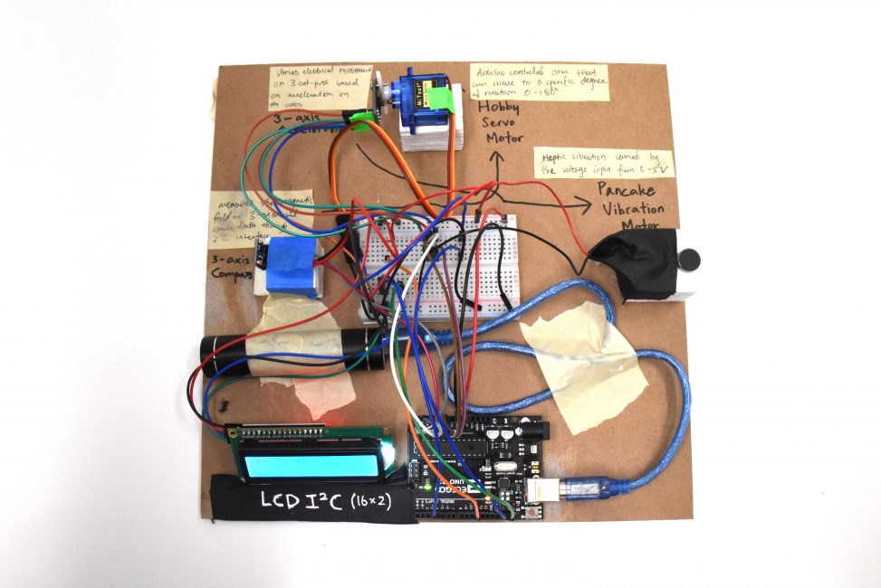
This is a double transducer that converts magnetic field (first input signal) into a motor movement (first output and second input signal) generated by reading the orientation of the motor, then reads that signal to convert to vibration (second output signal). This double conversion overall allows the magnetic field strength to be converted to vibration strength.
Sequence:
- (input 1, magnetic field strength) The triple-axis compass magnetometer sensor provides analog magnetic field strength data. The closer the magnet, the stronger the magnetic field strength that is detected by the sensor.
- (output 1, input 2, movement) The numbers from the sensor make the hobby servo motor to move within the range of 0 to 90 degrees. As the motor creates a movement, the ADXL335 analog accelerometer that is attached to the motor detects the change in orientation.
- (output 2, vibration strength) Then, this data is sent to the pancake vibration motor, generating vibration of according strength.

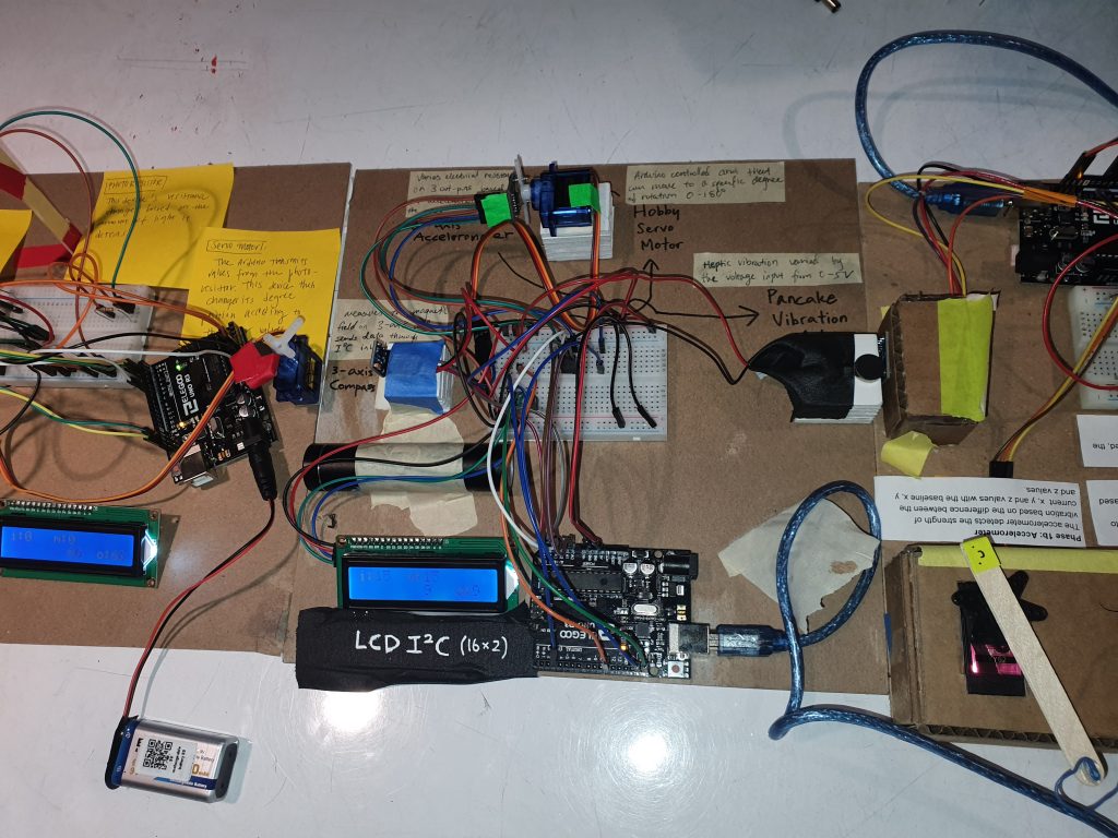
Overall photo
Detail Images:
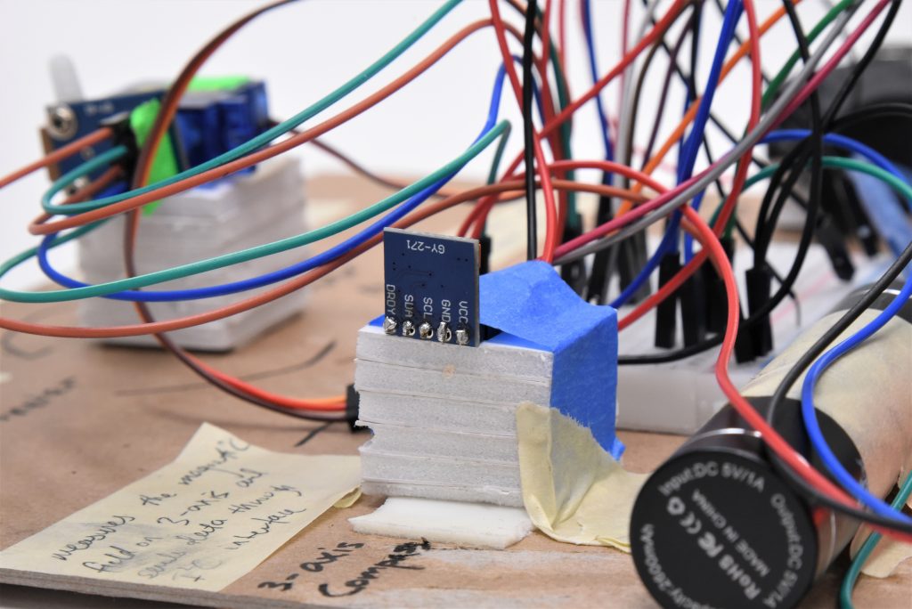
Triple-axis compass magnetometer sensor with its 5-pin header on the back side
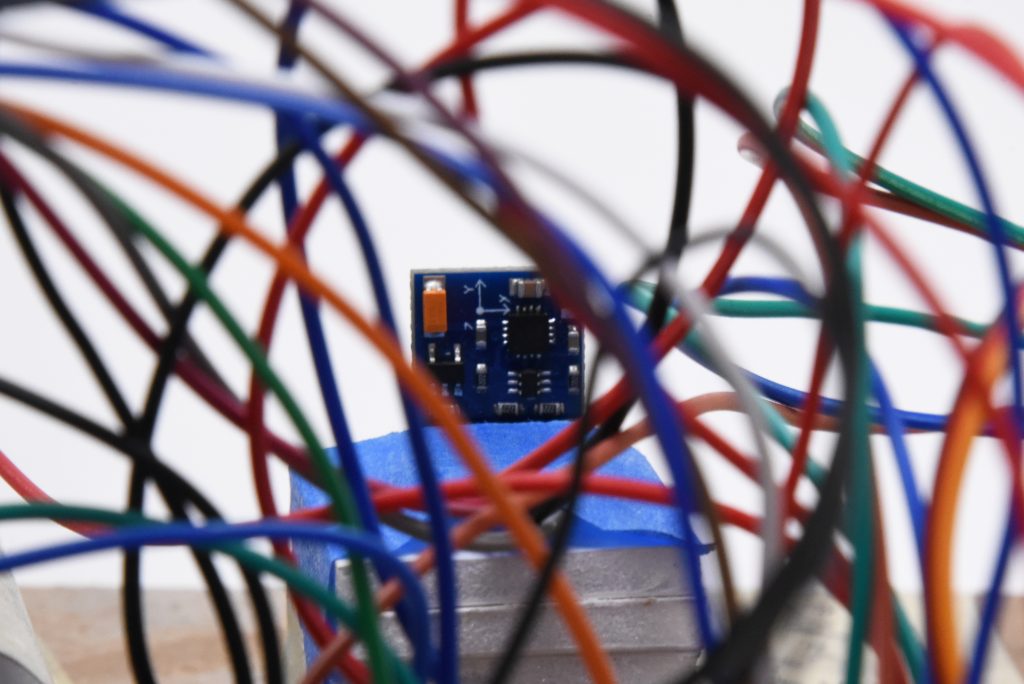
Triple-axis compass magnetometer sensor with its x, y, z axes marking
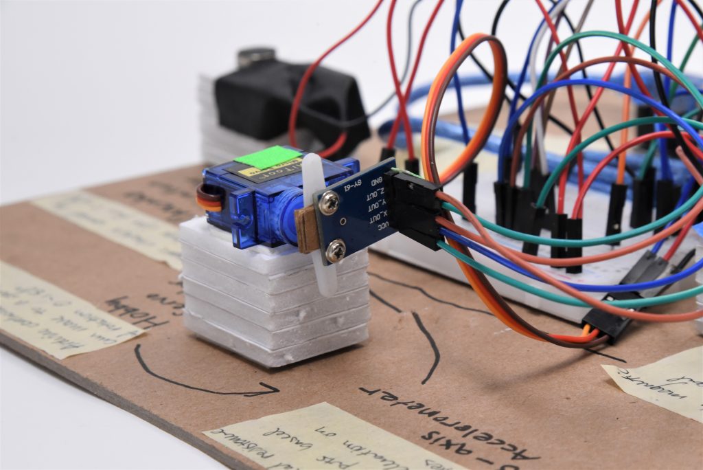
Hobby servo motor with ADXL335 analog accelerometer fixed on
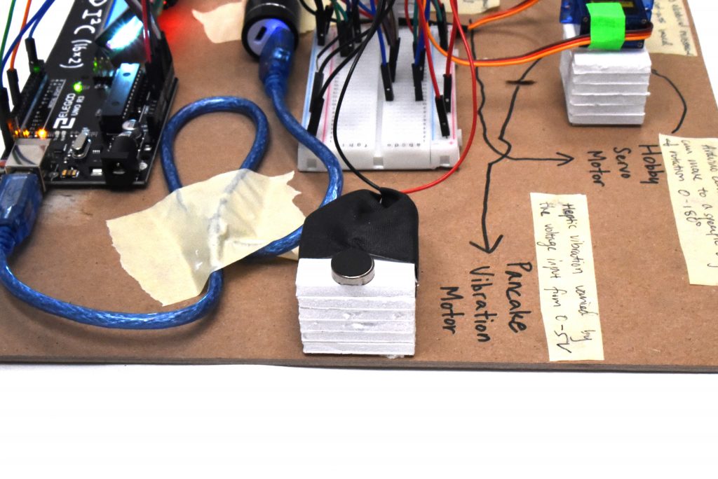
Pancake vibration motor
Video:
Progress Images:
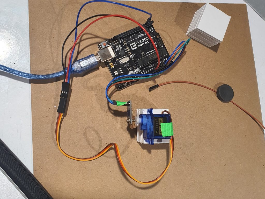
Intermediate testing step to figure out the motor integration
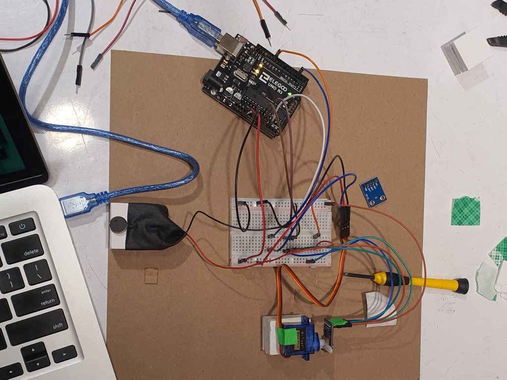
Parts assembled except for the LCD and magnetometer; serial monitor used to debug
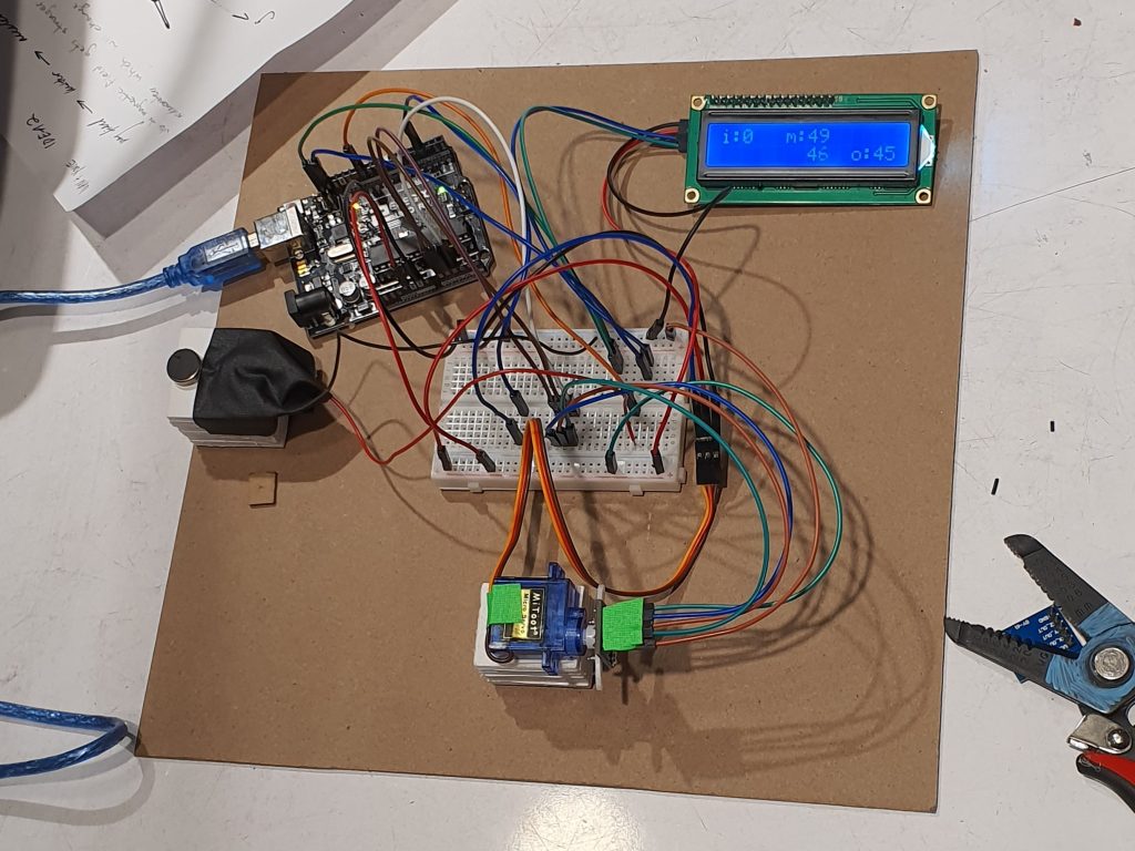
All parts assembled and working except for the magnetometer
Discussion:
We initially had a hall effect sensor to detect the magnetic field, but we replaced it with the triple-axis compass magnetometer sensor so that we could have analog, instead of digital, data. This was perhaps the hardest part because finding the right library took some time, and figuring out the range and calibrating were difficult because the sensor would overload when the magnet got too close to the sensor.
A physical difficulty was fixing the accelerometer well to the hobby servo body and adjusting the angles to be consistent with the angles in the code. We had to use some cardboard pieces to account for the length of the screw and the limited space to put the screw through while making the connection tight, and we had to do some trial and error for making sure that the motor along the correct range of angles. We also had to be careful with the pancake vibrator because the wires were very thin. We resolved by soldering and fixing the vibrator with tape onto the raised foam core board platform.
The challenge towards the end was mapping the magnetic field input range to appropriately to the previous group’s output. Because the magnetic field strength was weaker than anticipated, it was difficult to output the vibration strength strongly enough for the next group to have a good input range.
Some things that were straightforward were wiring and mapping the LCD display system and the movement mechanism parts because they were largely covered during class. Figuring out how to output signals with motors was also relatively easy.
We could gain soldering skills, and learn how to easily calibrate and map values across various parts. We could have done better with wire color-coding.
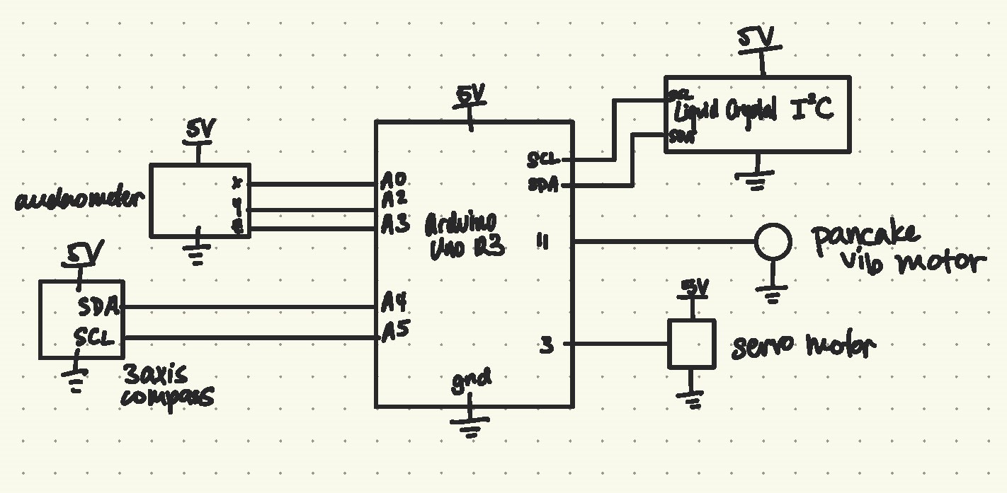
Schematic:
Code:
/* Title: Double Transducer: Magnetic Strength to Vibration Strength
 * Authors: Ivan Zhang and Youie Cho
 * Libraries: LiquidCrystal by Arduino, Adafruit, QMC5883LCompass by
 * MRPrograms
 *
 *
 */

//all the libraries
#include <Servo.h>
#include <math.h>
#include <Wire.h>
#include <LiquidCrystal_I2C.h>
#include <QMC5883LCompass.h>
LiquidCrystal_I2C screen(0x27, 16, 2); //create screen called screen
QMC5883LCompass compass; //create compass named compass
Servo steeringMotor; //create a motor object called steeringMotor

//naming all used pins
const int XPIN = A0;
const int YPIN = A1;
const int ZPIN = A2;
const int MOTORPIN = 3;
const int BUZZPIN = 11;

//setup timing
unsigned long timer = 0;
const int INTERVAL = 500;

//naming the intensity of the axis and buzzer
int xAxis;
int buzzInt;
int motorAngle;
int magStr;

//naming the output to LCD
int magPrint;
int buzzPrint;
int motorPrint;
int accPrint;

//defining the range of the input
int magMin = 6000;
int magMax = 8100;

void setup(){
  //set up motor
  steeringMotor.attach(MOTORPIN);

  //set up accelerometer
  pinMode(XPIN, INPUT);
  pinMode(YPIN, INPUT);
  pinMode(ZPIN, INPUT);

  //set up buzzer
  pinMode(BUZZPIN, OUTPUT);
  Serial.begin(9600);

  //set up screen
  screen.init();
  screen.backlight();
  screen.home();

  //set up compass
  compass.init();
}

void loop(){
  //get compass data
  compass.read();
  magStr = abs(compass.getY());

  //TRANSDUCER 1
  //map mag strength to motor angle
  motorAngle = abs(map(magStr,magMin,magMax,0,180));
  //set motor angle
  steeringMotor.write(motorAngle);

  //TRANSDUCER 2
  //map the XPIN to the angle from the rotation
  xAxis = abs(map(analogRead(XPIN), 400, 280, 0, 180));
  //map the buzzer intensity from the xAxis
  buzzInt = map(xAxis, 0, 180, 0, 255);
  //set buzz intensity
  analogWrite(BUZZPIN, abs(buzzInt));

  //debugging serial
  Serial.print(magStr);
  Serial.print(',');
  Serial.print(motorAngle);
  Serial.print(',');
  Serial.print(analogRead(XPIN));
  Serial.print(',');
  Serial.println(buzzInt);

  delay(100);


  //timer for LCD
  if (millis() >= timer){
      //reset screen
      screen.clear();
      screen.setCursor(0, 0);
      screen.print("i:    m:");
      screen.setCursor(12,1);
      screen.print("o:");

      //map each value to 0-99 for printing
      magPrint = map(magStr, magMin, magMax, 0, 99);
      motorPrint = map(motorAngle, 0, 180, 0, 99);
      accPrint = map(xAxis, 0, 180, 0, 99);
      buzzPrint = map(buzzInt, 0, 255, 0, 99);

      //print numbers
      screen.setCursor(2,0);
      screen.print(magPrint);
      screen.setCursor(8,0);
      screen.print(motorPrint);
      screen.setCursor(8,1);
      screen.print(accPrint);
      screen.setCursor(14,1);
      screen.print(buzzPrint);
      timer = millis() + INTERVAL;
  }
}
Double Transducer in Context:
Comments are closed.