Magnetic Field to Vibration Strength
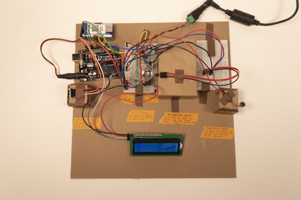
Full image of the Double Transducer: Magnetic Field to Vibration Strength
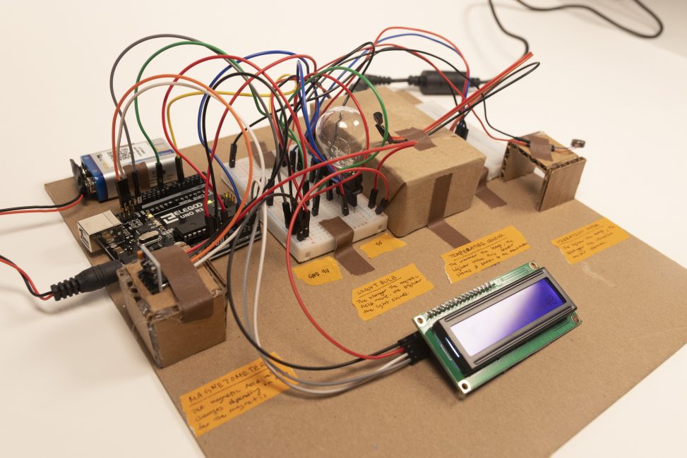
Full image of the Double Transducer: Magnetic Field to Vibration Strength. (At an angle)
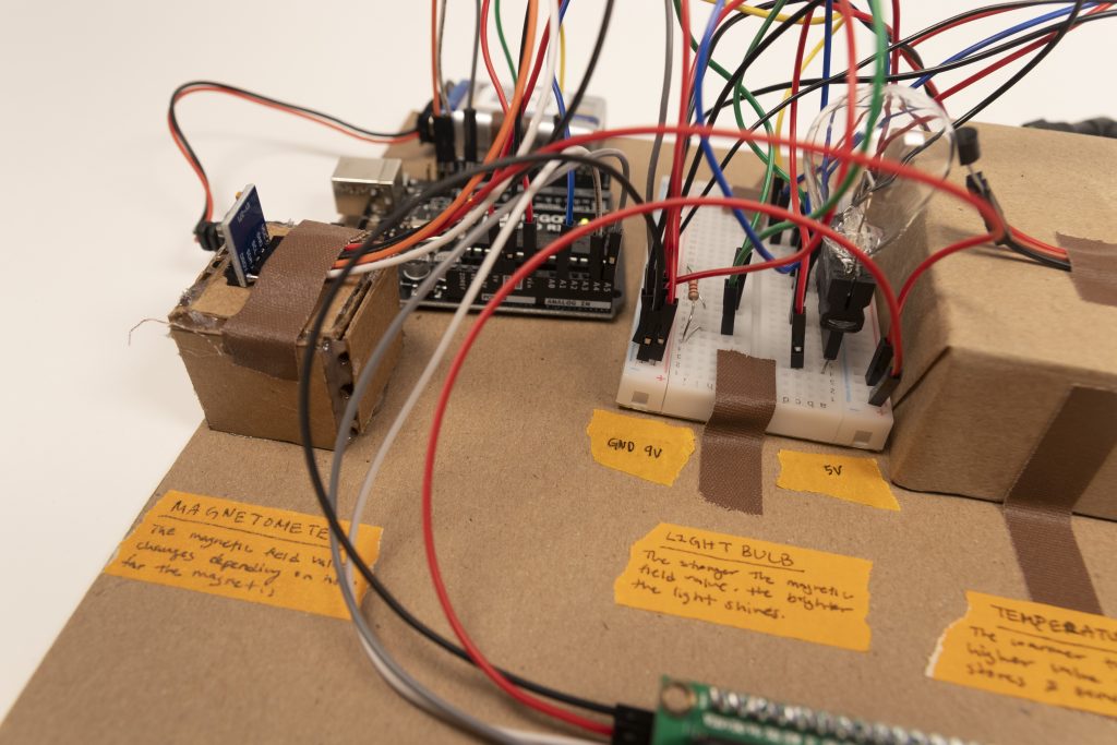
Close up of Magnetometer (input) to Light Bulb (output). The magnetometer detects the magnetic strength from the magnet’s distance. This causes the light bulb to light up in different ranges of brightness.
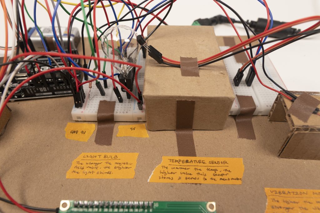
Close up of Light Bulb (Output) and Temperature Sensor (Input). The temperature sensor detects the different ranges of temperature the light bulb is emitting from the light bulb’s different brightness.
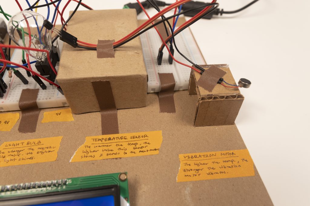
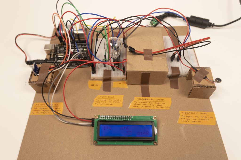
Close up of Temperature Sensor (Input) and Vibration Motor (Output). The range of temperature the temperature sensor detects determines the different ranges of strength the motor vibrates.
Description
We created a double transducer which is a device that converts magnetic field (such as the force of a magnet) through two more activities/functions to produce vibration strength (how fast something vibrates).
In our project, the farthest to the left is the magnetometer (the blue rectangular chip), which detects the magnetic field from having a magnet come closer or farther in distance to the chip. We coded this magnetometer so that it only detects forces from its x-axis (one side of this chip). Continuing on is the light bulb to the right. The lightbulb will turn on in different brightness when the magnet is at different distances to the magnetometer. The closer the magnet or when the magnetic field strength is high, the light bulb gets brighter. The lightbulb will produce heat and this will trigger the next mechanism, the temperature sensor (the black half cylinder with three legs/prongs). The temperature sensor will detect the temperature surrounding itself and once it gets to a certain degree, it will trigger a vibration motor (the small metal disk to the very right). The higher the temperature, the more the vibration motor will shake.
Process Images
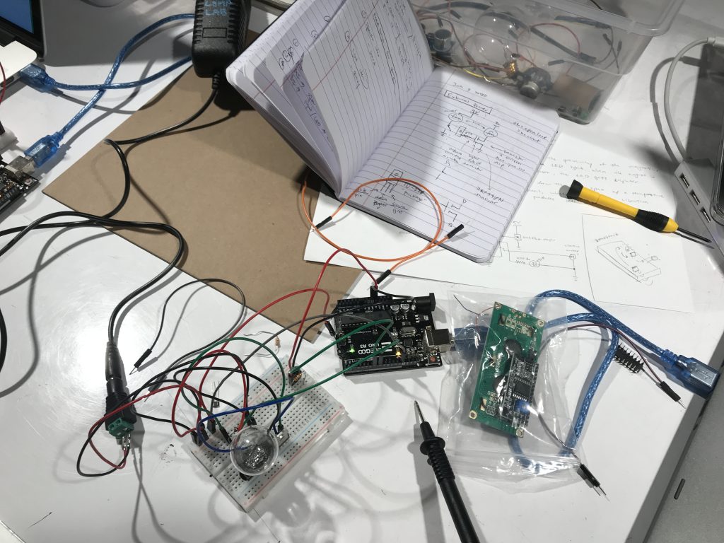
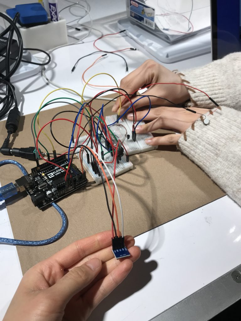
This was the beginning of us building the hardware of this project.
In the beginning, we were using a hall sensor, but it was not as effective, so we changed to the magnetometer.
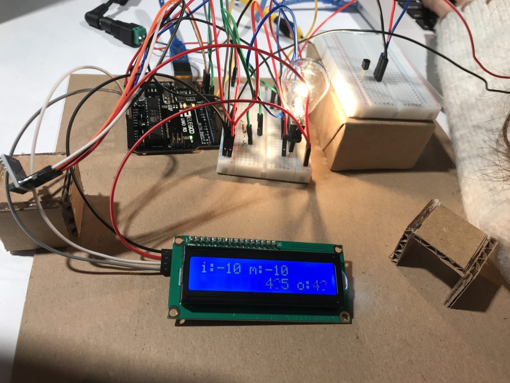
We were stuck on our I^2C LCD Screen numbers for a long time. It portrayed the wrong data (it had negative and triple-digit numbers).
Discussion
The easy part of the project was figuring out our idea and what our middle transducers would be. The planning for this was quite interesting as there were many input and output parts we could play with. We learned a lot from drawing each of the possible project schematics and finding different Arduino parts we could use. The most difficult part was the actual assembly of these parts and making them communicate with each other, especially since the temperature sensor was very sensitive and caused a lot of noise in the data and unstabilized the values. The unstable temperature values also led to difficulty in coding for the vibration motor.
Hands-on experience is the fastest way to learn something. After completing this project, we not only learned about Arduino parts that we never knew before but also essential concepts for wiring, such as using external batteries and power sources for parts that needed more than 5 volts. Getting stuck on writing the code and then solving the problems, helped us to remember how to problem-solve with Arduino and better prepare us for similar future problems.
If we were able to do this project again, we would have changed the temperature sensor to another mechanism because it was causing us many problems and was overall not an effective transducer. We could have used a LDR (light dependent resistor) to measure the intensity of the light to trigger our vibration motor.
SCHEMATIC
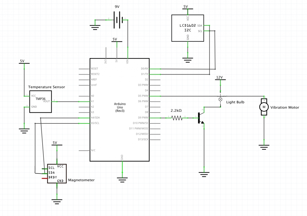
Our schematic for our double transducer
CODE
/*
   Title: Double Transducer: Magnetic Field to Vibration Strength
   Author: Hojung Kim and Patricia Yu

   Description: The magnetometer (input) measures the magentic strength
   from the distance of the magnet. This causes the light bulb (output)
   to light up in different ranges of brightness. Next, the temperature
   sensor (TMP36 - input) detects the ranges of the temperature the light
   bulb emits from light bulb's different brightness. The different
   temperature the temperature sensor detects determines the different
   strength of the vibration in the vibration motor.
  _____________________________________________________

   Pin mapping:
   pin   | mode   | description
   ------|--------|------------
   A1     input     TMP36 - temperature sensor
   09     output    light bulb
   05     output    vibration motor
  _____________________________________________________

  Credits:
  Temperature Measuring and Conversion Code (Specifically for TMP36):
  https://learn.adafruit.com/tmp36-temperature-sensor/using-a-temp-sensor by lady ada
  https://www.bc-robotics.com/tutorials/using-a-tmp36-temperature-sensor-with-arduino/ by Chris at BCRobotics

  Magnotometer/Compass code library:
  QMC5883LCompass by MRPrograms

  I^2C LCD Screen code library:
  LiquidCrystal_I2C by Frank De Brabander\

  Classmate Meijie and Chloe for helping us decode the LCD

*/

//code added from library:
#include <Wire.h>
#include <LiquidCrystal_I2C.h>
#include <QMC5883LCompass.h>

//LCD screen setting initialized
LiquidCrystal_I2C screen(0x27, 16, 2);
int x = 123;

QMC5883LCompass compass;
const int LIGHTBULB = 9;
const int TMP36 = A1; //TMP36 initial temperature range 0° to 175° (0V to 1.75V)
const int VIBRATE = 5;

double voltage; //The variable we will use to store temperature in degrees.
unsigned long timer = 0; // variable for timing
const int INTERVAL = 200; // milliseconds between updates

void setup() {
  Serial.begin(9600);
  compass.init();
  pinMode(LIGHTBULB, OUTPUT);
  pinMode(TMP36, INPUT);
  pinMode(VIBRATE, OUTPUT);

  //Sets up the LCD Screen startup:
  screen.init();
  screen.backlight();
  delay(1000);

  screen.clear();
  screen.home();
  screen.print("i:");

  screen.setCursor(6, 0);
  screen.print("m:");

  screen.setCursor(8, 1);

  screen.setCursor(12, 1);
  screen.print("o:");
}

void loop() {

  //input - compass (magnetic strength):
  int x = 0;
  compass.read(); // Read compass values
  x = compass.getX(); // Return XYZ readings

  //middle output - light (brightness):
  int lightVal = map(x, -2000 , 6000, 0, 255); //limit the range of the light to 0-255
  lightVal = constrain(lightVal, 0, 255);
  analogWrite(LIGHTBULB, lightVal);

  // middle input - temperature sensor:
  int sensorInput = analogRead(TMP36); //read the analog sensor and store it
  voltage = (double)sensorInput / 1024; //find percentage of input reading
  voltage *= 5.0; //multiply by 5V to get voltage

  int temperatureC = (voltage - 0.5) * 100; //Subtract the offset and convert to degrees Celsius

  //output - vibration motor:
  int vibVal = map(temperatureC, 0 , 65, 0, 255); //limit the range of the light to 0-255
  temperatureC = constrain(temperatureC, 0, 255);
  vibVal = constrain(vibVal, 0, 255);

  if (temperatureC >= 30) { //when the tempereature is greater than or equal to 30°C the vibration vibrates at different range
    analogWrite(VIBRATE, vibVal);
  }

  else { // when the tmeperature is anything less than 30°C  it will turn off
    analogWrite(VIBRATE, 0);
  }

  // run LCD screen update procedure
  if (millis() >= timer) {
    timer = millis() + INTERVAL; // and update timer

    //limit the range of the light to 0-99
    screen.setCursor(2, 0);
    int magno = map(lightVal, 0, 255, 0, 99);
    screen.print(magno);

    screen.setCursor(8, 0);
    int light = map(lightVal, 0, 255, 0, 99);
    screen.print(light);

    screen.setCursor(8, 1);
    screen.print(temperatureC);

    screen.setCursor(14, 1);
    int vibration = map(vibVal, 0, 255, 0, 99);
    screen.print(vibration);
  }

}
Comments are closed.