Title
Double Transducer – Vibration Strength to Distance to Color
Video of the machine doing it’s task
Description
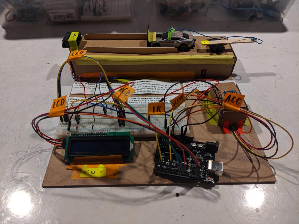
The machine created first senses vibration strength using an accelerometer and depending on the vibration strength, will rotate a servo motor to a specific angle between 0 and 90 degrees. The rotation of the servo motor will push or pull a toy car to a specific linear location. This distance will be detected by an IR sensor and depending on the sensor’s reading, it will change the color of a diffused RGB LED.
Progress Images
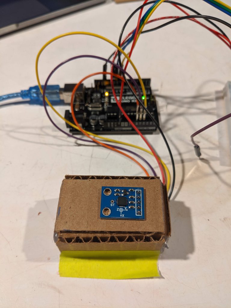
Creating a case for the accelerometer
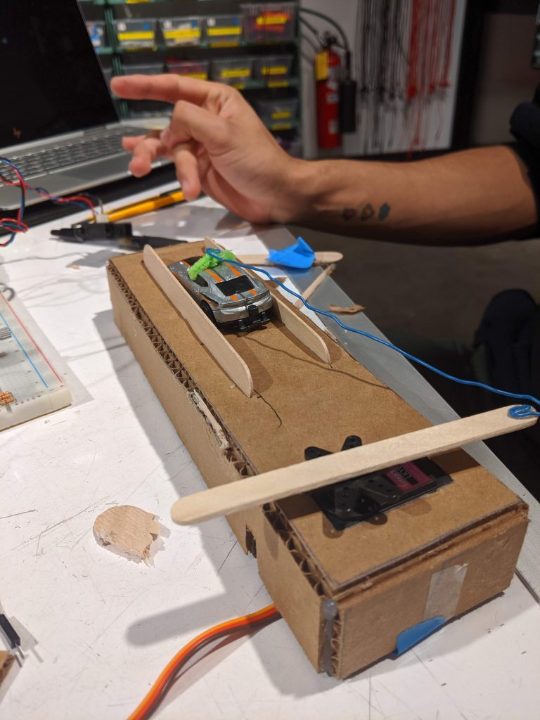
Creating a servo motor that pushes and pulls a toy car
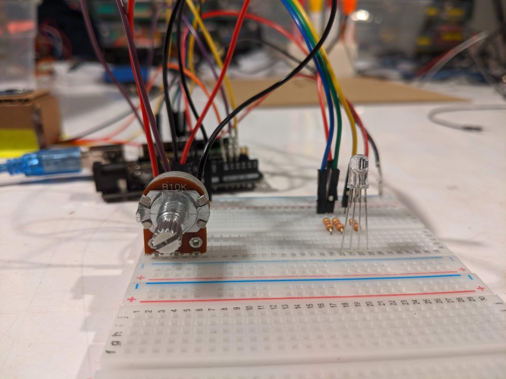
Configuring of the RGB LED
Process Discussion
1. Detecting vibration strength
We decided to use an accelerometer to detect vibration strength. In order to ensure that it is stable, we built a case for it and ensured that it is attached to our board.
The readings for the accelerometer at rest was around 300 for all the three axis. We decided that we wanted to take into account all the different axis to detect the strength of the vibration to provide with more flexibility and accuracy for the orientation of the source of vibration. One thing we realized was that depending on slight movements of the case on the board or the position of the entire board, the readings for the accelerometer would change. This was not ideal because it meant that the baseline was constantly changing between runs. We decided to add a momentary pushbutton to set the baseline of the values.
We calculated the strength of vibration by taking the average of the absolute difference between the actual x, y and z axis accelerometer reading with the baseline x, y, z axis accelerometer reading.
In order to test out the accuracy of our vibration strength sensor, we used a pancake sensor, which the team before us are using. By using the 5V and 3.3V pins, we were able to create different vibration strengths. With this, we could also figure out what would be the upper bound of the vibration strength.
It was challenging working with the pancake motor because the legs were really short. In order to solve this, we would strip the legs and solder them to more sturdy wires. However, it was very fragile and did not last long. In the end, we settled with taping the pancake motor to the sensor.
2. Improving accuracy of intermediate step
One of the problems about using a servo motor to move a toy car is the accuracy of it. In order to improve the accuracy, we decided to create railings for the car so that it would make it a linear movement.
Another thing we did to improve the readings from the IR sensor is attaching a black aluminium foil to the front of the toy car.
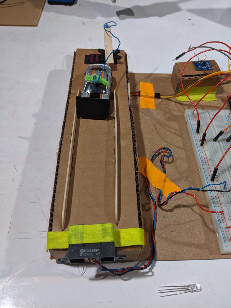
Increasing accuracy of IR sensor reading
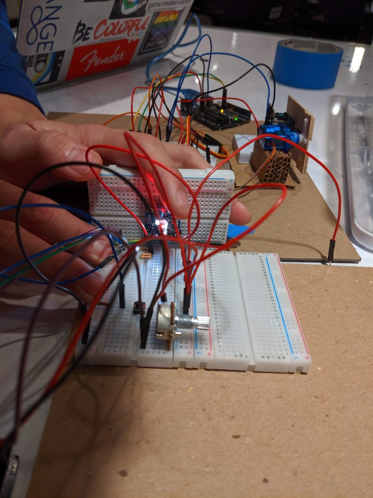
3. selecting the colored lights
We took some time to figure out how to get the RGB LED working because there were different types of LED – some LEDs would require connection to ground whereas some others would require us to connect to power. We also found out that the readings for the LED we were using was inverse of the software code we had to write.
After we got past figuring out how to make the LED light up, we had to decide how to make the colors change from red to purple. We wanted to make it very gradual, where it would have multiple intermediate colors between two main colors (like red and yellow would go through the entire shade of red to red-orange, to orange to orange-yellow). This was taking a lot of time and we felt that it would be more efficient to hard code the specific colors.
One last problem we faced was that it was hard for the next team to detect the colors from the RGB LED we were using. We then explored different alternatives available and realized that diffused RGB LED make the colors eas
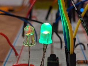
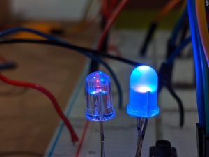
Comparing between RGB LED and Diffused RGB LED
Testing diffused RGB LED
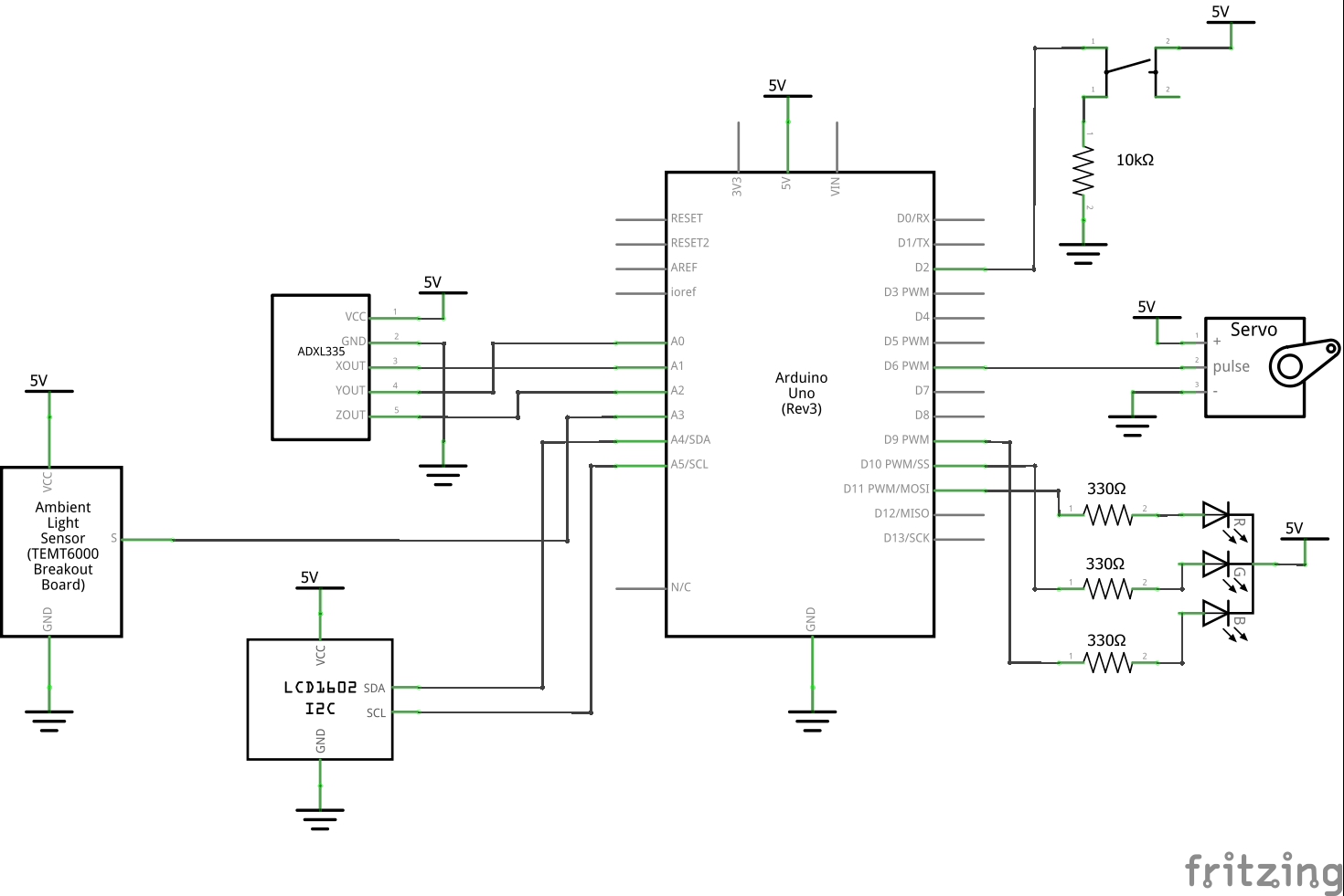
Schematic
Code submission
/*
 * Project 1: Double Transducer
 * Estevan Chairez & Zoe Teoh
 *
 * Description:
 *
 * Double Transducer - Vibration Strength to Distance to Color
 * -------------------------------------------------------------
 * The machine created first senses vibration strength using an accelerometer and
 * depending on the vibration strength, will rotate a servo motor to a specific angle
 * between 0 and 90 degrees. The rotation of the servo motor will push or pull a toy
 * car to a specific linear location. This distance will be detected by an IR sensor
 * and depending on the sensor's reading, it will change the color of a diffused RGB LED.
 *
 * PHASE 1: Vibration strength
 * This code will wait for momentary button to be pressed to start
 * storing all the values of the accelerometer and convert it into a single value.
 *
 * PHASE 2: Distance
 * This will then be converted to a value between that a servo can accept. This value
 * will then cause the servo to push a car closer/further to an IR Sensor.
 *
 * PHASE 3: Color
 * The IR Sensor will detect the car's distance and convert
 * that to a separate RGB value with a function to power an RGB LED with a
 * certain color.
 *
 *
 * Pin mapping:
 *
 * pin   | mode   | description
 * ------|--------|------------
 * A0      input    Y-Axis of accelerometer
 * A1      input    X-Axis of accelerometer
 * A2      input    Z-Axis of accelerometer
 * A3      input    IR Sensor
 * SCL     output   LCD Screen
 * SDL     output   LCD Screen
 * 2       input    momentary push button
 * 6       output   servo motor
 * 9       output   blue LED
 * 10      output   green LED
 * 11      output   red LED
 */

#include <LiquidCrystal_I2C.h>
#include <Wire.h>
#include <Servo.h>


const int RED = 11;
const int GREEN = 10;
const int BLUE = 9;
const int Z = A2;
const int Y = A0;
const int X = A1;
const int SERVO = 6;
const int IR = A3;
const int BUTTON = 2;

int baseX;
int baseY;
int baseZ;
int angle;
int middle_1;
int input;
int accel_difference;
bool start = false;


// RGB values to send to LED
int colors[][3] = {{255, 0, 0}, {255, 255, 0}, {0, 255, 0}, {0, 255, 255}, {0, 0, 255}, {255, 0, 255}};

// command to send RGB [R, G, B] color to RBG LED
void rgb(int red_light_value, int green_light_value, int blue_light_value) {
  analogWrite(RED, 255 - red_light_value);
  analogWrite(GREEN, 255 - green_light_value);
  analogWrite(BLUE, 255 - blue_light_value);
}


// command to convert an int to a color in R, G, B spectrum "int -> [R, G, B]"
void intToRGB(int val) {
  int r = colors[val][0];
  int g = colors[val][1];
  int b = colors[val][2];
  rgb(r, g, b);
}


// set up LCD and display certain values in the form
// i: input  m: middle_1
//              middle_2  o: output
//
void lcd(LiquidCrystal_I2C screen, int input, int middle_1, int middle_2, int output) {
  input = constrain(input, 0, 99);
  middle_1 = constrain(middle_1, 0, 99);
  middle_2 = constrain(middle_2, 0, 99);
  output = constrain(output, 0, 99);

  screen.clear();
  screen.setCursor(0, 0);
  screen.print("i:");
  screen.setCursor(2, 0);
  screen.print(input);
  screen.setCursor(6, 0);
  screen.print("m:");
  screen.setCursor(8, 0);
  screen.print(middle_1);
  screen.setCursor(8, 1);
  screen.print(middle_2);
  screen.setCursor(12, 1);
  screen.print("o:");
  screen.setCursor(14, 1);
  screen.print(output);
  delay(500);
}

LiquidCrystal_I2C screen(0x27, 16, 2);
Servo servo;

void setup() {
  // ACCELEROMETER Setup
  pinMode(Z, INPUT);
  pinMode(Y, INPUT);
  pinMode(X, INPUT);

  // LCD Screen Setup
  screen.init();
  screen.backlight();
  screen.home();

  // SERVO Setup
  servo.attach(SERVO);

  // OTHER PINS
  pinMode(BUTTON, INPUT);
  pinMode(RED, OUTPUT);
  pinMode(BLUE, OUTPUT);
  pinMode(GREEN, OUTPUT);
  pinMode(IR, INPUT);


  Serial.begin(9600);
}


void loop() {


  // ACCELEROMETER CODE

  int zVal = analogRead(Z);
  int yVal = analogRead(Y);
  int xVal = analogRead(X);
  int buttonState = digitalRead(BUTTON);


  // will not do anything until momentary push button is pressed
  if (buttonState && !start) {

    baseX = xVal;
    baseY = yVal;
    baseZ = zVal;
    start = true;
  } else {

    accel_difference = abs(baseX - xVal) + abs(baseY - yVal) + abs(baseZ - zVal);
    input = map(accel_difference, 0, 250, 0, 99);

    // CAR - SERVO CODE
    if (baseX != 0 && baseY != 0 && baseZ != 0){
      angle = map(accel_difference, 0, 250, 0, 90);
      servo.write(angle);
      middle_1 = map(angle, 0, 90, 0, 99);
    }


    // DISTANCE SENSOR CODE
    int dis = analogRead(IR);
    int middle_2 = map(dis, 465 , 300, 0, 99);


    // LED CODE
    int convertedVal = constrain(map(dis, 465, 300, 0, 5), 0, 5);
    intToRGB(convertedVal);
    int output = map(convertedVal, 0, 5, 0, 99);


    // LCD DISPLAY
    lcd(screen, input, middle_1, middle_2, output);
  }

}
Comments are closed.