[the featured photo is closest to original product I could get because I could not get high quality pictures]
Background
Dropfoot is a condition where the person, when walking, cannot lift their foot up towards their body when walking.
A short video about drop foot:
Short Description
A shoe that uses sensors to determine your foot position and lifts your foot manually when you walk.
[could not include high-quality photos due to not being on campus]
Process
I started out making a smaller version of the mechanics of the final aid, using one pressure sensor[to be attached to the front part of the foot] and 2 servo motors and this is how the prototype worked:
My biggest concern at this point was if the bigger servo motors that I was planning on using could support the weight of the shoe and the foot in it for the upward motion. Then, I realized that with only one pressure sensor, the experience of the person wearing the aid would be affected when the foot comes down to meet the floor because they would be pushing against the upward force of the servo. This led me to include a second pressure sensor[attached to the back of the foot] to manually move the foot back to the starting position.
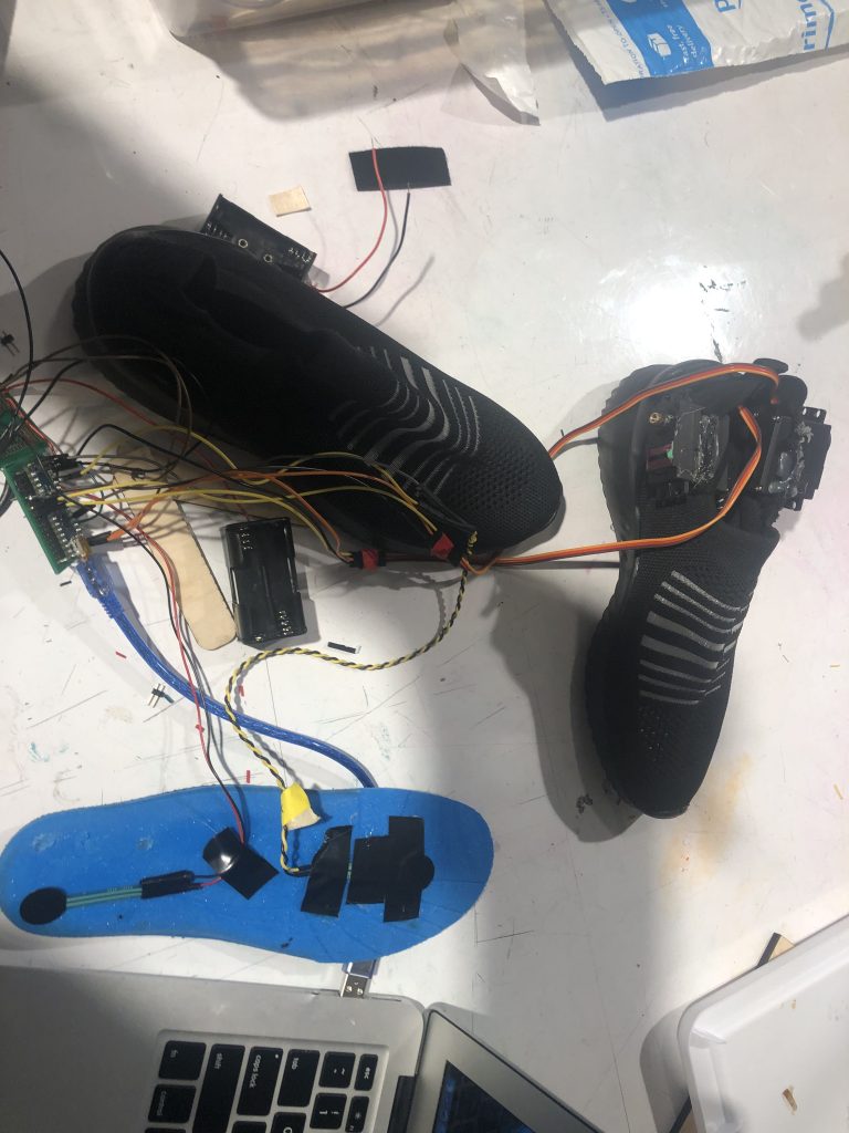
One pressure sensor at the front of the foot and one at the back
The next concern was the wearability of the device. The Arduino Uno R3 is a bigger version of the Arduino boards. So I decided to use and Arduino nano to make more practical.
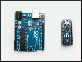
The comparison of Arduino Nano and Uno[I could not get the picture of the nano on the shoe]
I also decided to solder the servos, battery pack for the servos, and the 2 pressure sensors on to a small proto-board to make it more wearable and durable. A big problem I ran into while doing this is that many wires would break, especially the red and black wires on the battery pack. I used some silicone epoxy on top of the battery pack to prevent this from happening again.
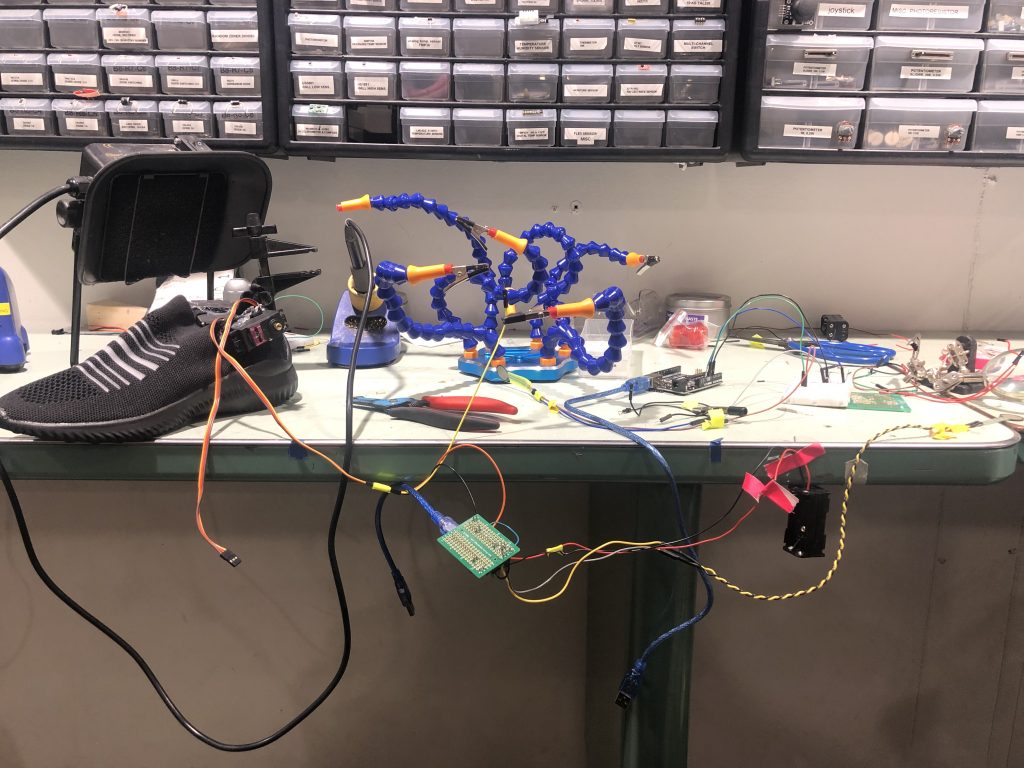
Size of the proto-board and soldering process[I could not get a closer picture since I don’t have access to my project]
To test out whether the motion of the brace was working correctly:
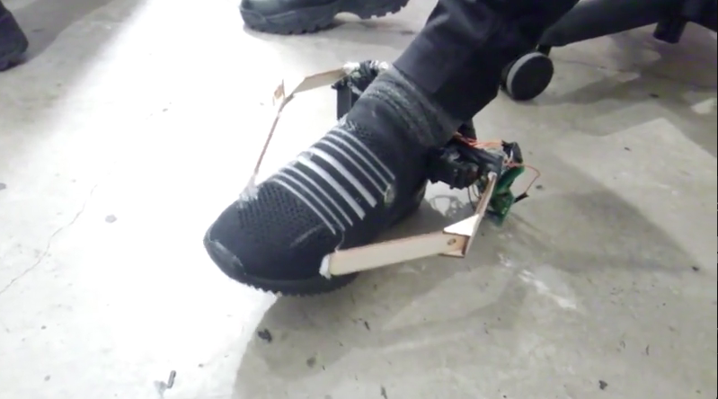
At this point, I laser cut these two braces in the place of the popsicle sticks seen above using wood:
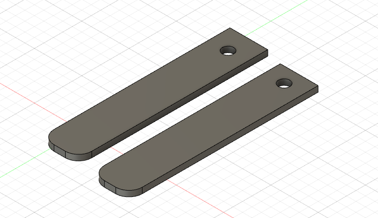
The braces that were attached to the servo motors on either side
After attaching both ends of the laser cut brace to the servo and shoe, I was disappointed to see that the shoe was not lifting at all despite the fact that servos were rotating at the right time[when the two pressure sensors recorded a pressure above a certain tested threshold]. The problem was that the brace was sticking out from the shoe at an angle because of the width of the servo, therefore being forced in the other direction to connect to the shoe. After discussing this issue with the professor, I decided to proceed by cutting out two more braces and connecting the addition brace on each side so that the existing brace was sticking out, but then the new brace would act as an extension by coming in to the shoe [I was not able to get a picture of this]. Then, for structural support, I laser cut 4 little triangles to attach to the area where the two braces on each side meet.
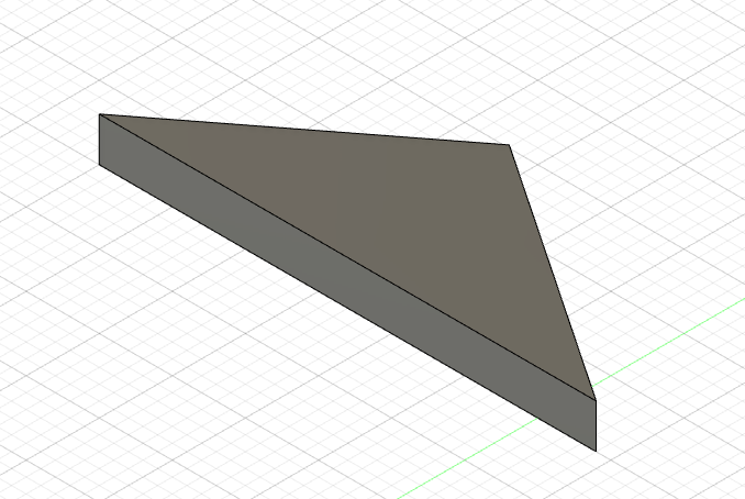
The little triangles used for structural support
I used both wood glue and super glue to attach these parts to the shoe.
In the end though, the aid did not work as planned and was not able to lift off of the ground at all.
Discussion
Before discussing some improvements/theories about why this project did not work out as planned, I would like to talk about the things that I enjoyed in this process and the things I did not. Although the outcome of the project was not what I expected, I am very happy with the fact that I was able to learn a lot from this project, get feedback from others, and get started on this idea that I feel will help and impact others in an incredibly positive way. The code worked well and was relatively easy to implement and debug, whereas planning the structure, design, and soldering the wires to the proto-board took the longest. I feel like this was the hardest for me because the wires kept breaking after I soldered them and I have no experience in building anything relying on structure and design.
The next thing that I believe that the project would have benefitted from is more thought into what kind of materials would work the best for the end goal. The braces I made were made of wood and wood is a heavy material. Perhaps using something light but strong, like a flat metal strip with holes in it might have worked. Also, gluing together many of the parts securely was difficult because I might have not used the right glue and the design was poor. The material of the shoe was fabric and I did not have the right type of glue to attach the servo to the shoe. In addition to that, the different forces acting on the already glued braces kept disbanding the glue whenever the braces moved. Therefore, in the further iterations of this project, I will have to pay special attention to the materials used in created the walking aid.
When presenting this project in class, I received some great feedback that I could take into consideration when I work on this project further. The first feedback I would like to discuss is:
Packaging is definitely a challenge with something like this. It’s a neat idea. Consider using something like Delrin for the arms. Coincidentally, Delrin is quite amenable to laser cutting.
This is really great advice because I don’t have much experience with laser cutters. I was wondering what can be used to make the arms more effective. Something that I would have to think about with this is what type of adhesive I would use to make it stable to whatever I am gluing it to.
Another comment I received was:
The device’s concept is intriguing and potentially extremely useful. However, I think that the craft of the device is hindering its functioning. Have you considered other methods of attaching the device?
I definitely agree with this comment. I feel like there is a better way to design this walking aid because of the difficulties that the current positions of the servo motors cause. I am considering maybe one high torque servo attached to the back of the shoe that moves up and down. That could possible make it easier to work with.
I will definitely continue improving and working on this project. Presenting it to the class has allowed me to be able to think about the ways that I could improve the design and structure of this project to make it work.
Schematic
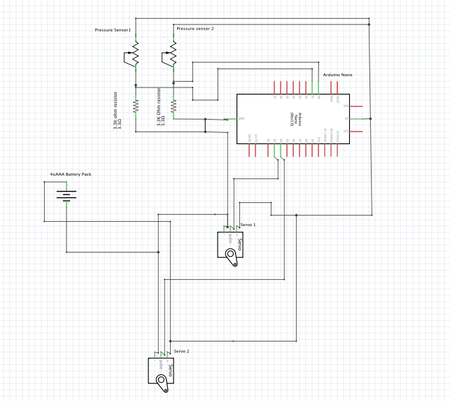
Schematic for walking aid
Code
- <span class="com">/*
- * Project 2
- * Varsha Shankar (varshas)
- * 2 weeks
- *
- * Collaboration:
- *
- * Challenge: this was a very starightforward block of code because I have wored with servos
- * and pressure sensors before.
- *
- * Next time: I will do more user testing to make the thresholds for action more accurate
- *
- * Description: The code below uses two pressure sensors to move a servo motor into two
- * different positions
- *
- * Pin mapping:
- *
- * pin | mode | description
- * ------|--------|------------
- * A0 input pressure sensor
- * A1 input pressure sensor
- * 3 output servo motor
- * 4 output servo motor
- *
- */</span><span class="pln">
- </span><span class="com">#include</span><span class="pln"> </span><span class="str"><Servo.h></span><span class="pln">
- </span><span class="kwd">const</span><span class="pln"> </span><span class="kwd">int</span><span class="pln"> FSRPIN </span><span class="pun">=</span><span class="pln"> A0</span><span class="pun">;</span><span class="pln">
- </span><span class="kwd">int</span><span class="pln"> fsrReading</span><span class="pun">;</span><span class="pln">
- </span><span class="kwd">const</span><span class="pln"> </span><span class="kwd">int</span><span class="pln"> FSRPIN1 </span><span class="pun">=</span><span class="pln"> A1</span><span class="pun">;</span><span class="pln">
- </span><span class="kwd">int</span><span class="pln"> fsrReading1</span><span class="pun">;</span><span class="pln">
- </span><span class="typ">Servo</span><span class="pln"> rservo</span><span class="pun">;</span><span class="pln">
- </span><span class="kwd">const</span><span class="pln"> </span><span class="kwd">int</span><span class="pln"> RSERVOPIN </span><span class="pun">=</span><span class="pln"> </span><span class="lit">3</span><span class="pun">;</span><span class="pln">
- </span><span class="kwd">int</span><span class="pln"> rservopos</span><span class="pun">;</span><span class="pln">
- </span><span class="typ">Servo</span><span class="pln"> lservo</span><span class="pun">;</span><span class="pln">
- </span><span class="kwd">const</span><span class="pln"> </span><span class="kwd">int</span><span class="pln"> LSERVOPIN </span><span class="pun">=</span><span class="pln"> </span><span class="lit">4</span><span class="pun">;</span><span class="pln">
- </span><span class="kwd">int</span><span class="pln"> lservopos</span><span class="pun">;</span><span class="pln">
- </span><span class="kwd">void</span><span class="pln"> setup</span><span class="pun">()</span><span class="pln"> </span><span class="pun">{</span><span class="pln">
- </span><span class="typ">Serial</span><span class="pun">.</span><span class="kwd">begin</span><span class="pun">(</span><span class="lit">9600</span><span class="pun">);</span><span class="pln">
- rservo</span><span class="pun">.</span><span class="pln">attach</span><span class="pun">(</span><span class="pln">RSERVOPIN</span><span class="pun">);</span><span class="pln">
- lservo</span><span class="pun">.</span><span class="pln">attach</span><span class="pun">(</span><span class="pln">LSERVOPIN</span><span class="pun">);</span><span class="pln">
- </span><span class="pun">}</span><span class="pln">
- </span><span class="kwd">void</span><span class="pln"> loop</span><span class="pun">()</span><span class="pln"> </span><span class="pun">{</span><span class="pln">
- fsrReading </span><span class="pun">=</span><span class="pln"> analogRead</span><span class="pun">(</span><span class="pln">FSRPIN</span><span class="pun">);</span><span class="pln">
- fsrReading1 </span><span class="pun">=</span><span class="pln"> analogRead</span><span class="pun">(</span><span class="pln">FSRPIN1</span><span class="pun">);</span><span class="pln">
- </span><span class="kwd">if</span><span class="pln"> </span><span class="pun">(</span><span class="pln">fsrReading </span><span class="pun">></span><span class="pln"> </span><span class="lit">550</span><span class="pun">){</span><span class="pln">
- delay</span><span class="pun">(</span><span class="lit">10</span><span class="pun">);</span><span class="pln">
- </span><span class="kwd">if</span><span class="pln"> </span><span class="pun">(</span><span class="pln">fsrReading </span><span class="pun"><</span><span class="pln"> </span><span class="lit">400</span><span class="pun">){</span><span class="pln">
- rservo</span><span class="pun">.</span><span class="pln">write</span><span class="pun">(</span><span class="lit">60</span><span class="pun">);</span><span class="pln">
- lservo</span><span class="pun">.</span><span class="pln">write</span><span class="pun">(</span><span class="lit">100</span><span class="pun">);}</span><span class="pln">
- </span><span class="pun">}</span><span class="pln">
- </span><span class="kwd">if</span><span class="pln"> </span><span class="pun">(</span><span class="pln">fsrReading1 </span><span class="pun">></span><span class="pln"> </span><span class="lit">50</span><span class="pun">){</span><span class="pln">
- rservo</span><span class="pun">.</span><span class="pln">write</span><span class="pun">(</span><span class="lit">100</span><span class="pun">);</span><span class="pln">
- lservo</span><span class="pun">.</span><span class="pln">write</span><span class="pun">(</span><span class="lit">60</span><span class="pun">);</span><span class="pln">
- </span><span class="pun">}</span><span class="pln">
- </span><span class="pun">}</span>
Comments are closed.