
Introduction
For the final project of Physical Computing(60-223) course at Carnegie Mellon University, each group of three CMU students was assigned to an Osher student to build an assistive device for the older adults. Our group had the fortune to work with an amazing Osher student who herself is a CMU alum, Emily Eckel. Through multiple stages of interviews, ideations, discussion, and critiques, we decided to create an entertaining ‘Mouse Detector’ that can detect mouse at her house so that she can bring her son’s cat from upstairs. The two most important goals of this project were functionality and entertainment. The device should be able to detect a mouse, nothing else, with high accuracy, and be able to notify Emily. On top of that, due to the COVID-19 pandemic situation, Emily had to spend more time at her house which makes her a bit depressed; thus she wanted a device that can give her small joy in daily life.
Although this project was initially planned to have an actual physical prototype in the end, because of the COVID-19 pandemic situation where all CMU courses have officially conducted remotely, we had no choice but to make this project virtual. To provide a more constructive and tangible overview of our idea to Emily and everyone in this process, we decided to make a physical crafted prototype, a CAD design simulation, and a circuit/technical prototype. For your reference, more details about the initial ideation and plans can be found here, and the initial model and details can be found here.
What We Built
We built a mouse detector, with two parts: the sensor unit which detects if a mouse is nearby, and the control panel unit that notifies Emily if a mouse has been detected and allows her to control the notifications. When a mouse is detected, the control panel lights up, and a small door opens and a mouse sign emerges. If it is daytime, music from Mickey Mouse plays. The volume knob controls the loudness of the music, and the brightness knob controls the brightness of the panel when it lights up. When the reset button is pressed, the mouse sign goes back in and the door closes, and light and music turns off.
Final appearance rendering
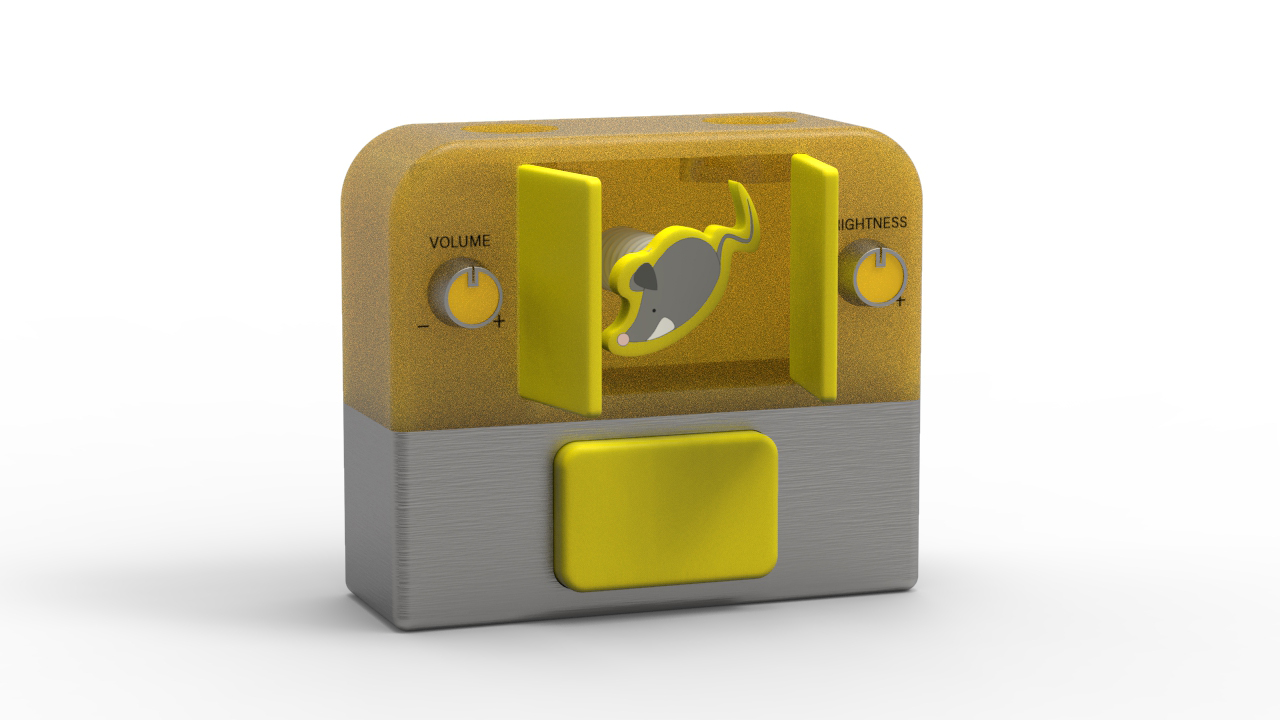
Overall image (character panel going back in after device has been reset)
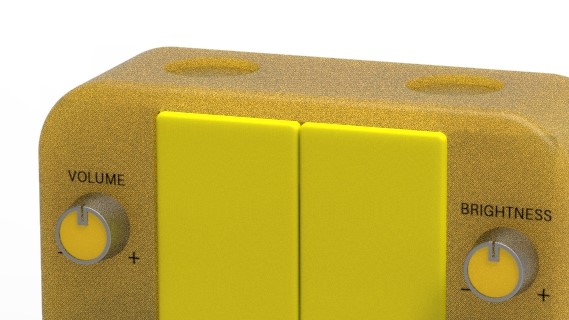
Volume and brightness control knobs
Speakers
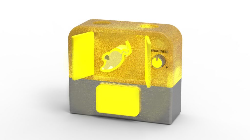
Notification on
Tinkercad Interaction
Physical MOCKUP
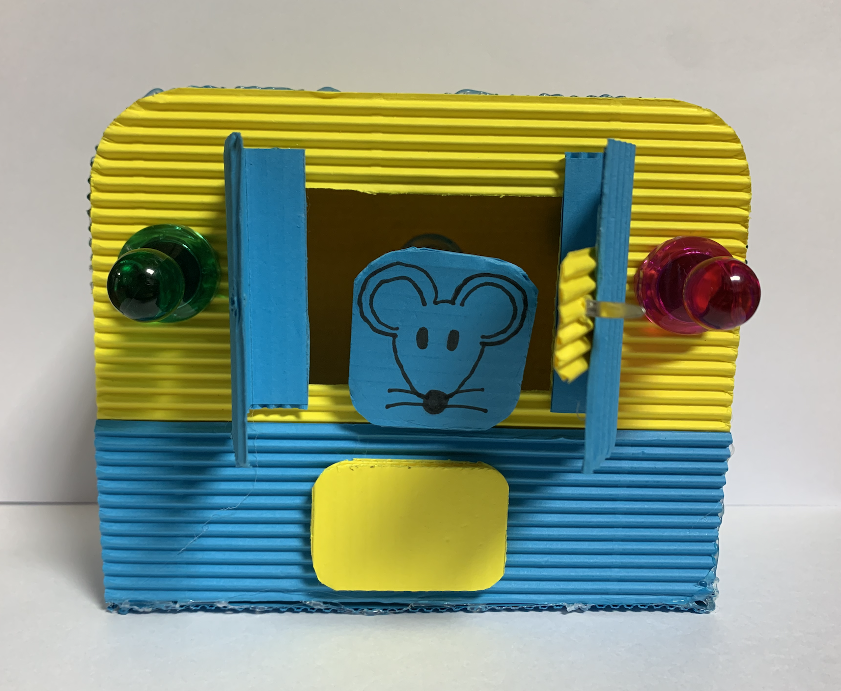
A front view of the controller unit crafted prototype (two green and red knobs each are volume and brightness controller, a door and a mouse panel is a cuckoo bird clock-like notification, and a yellow rectangular button is a reset button)
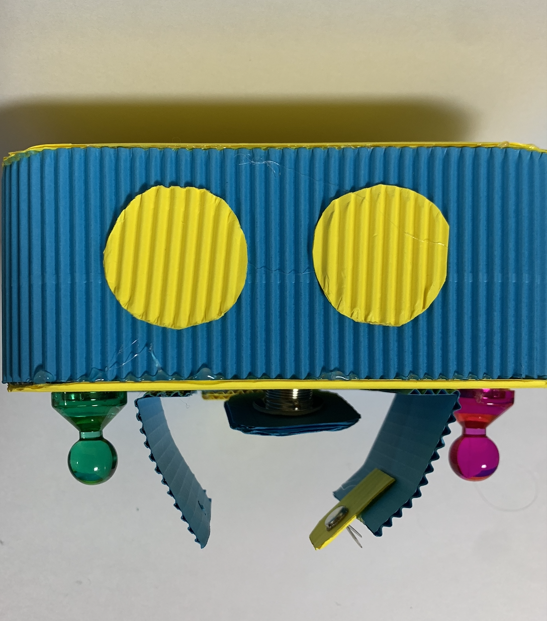
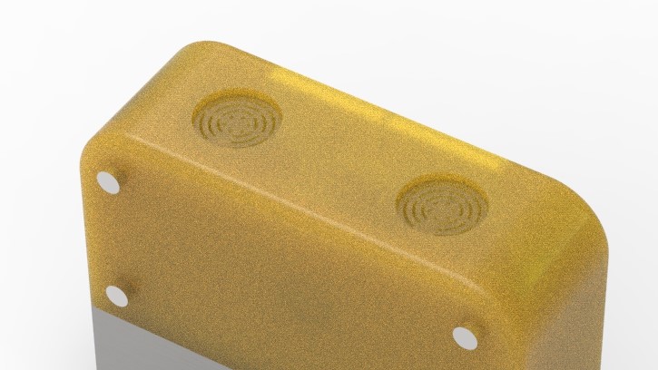
A top view of the controller unit crafted prototype (two yellow circles are a speaker unit for notifications)
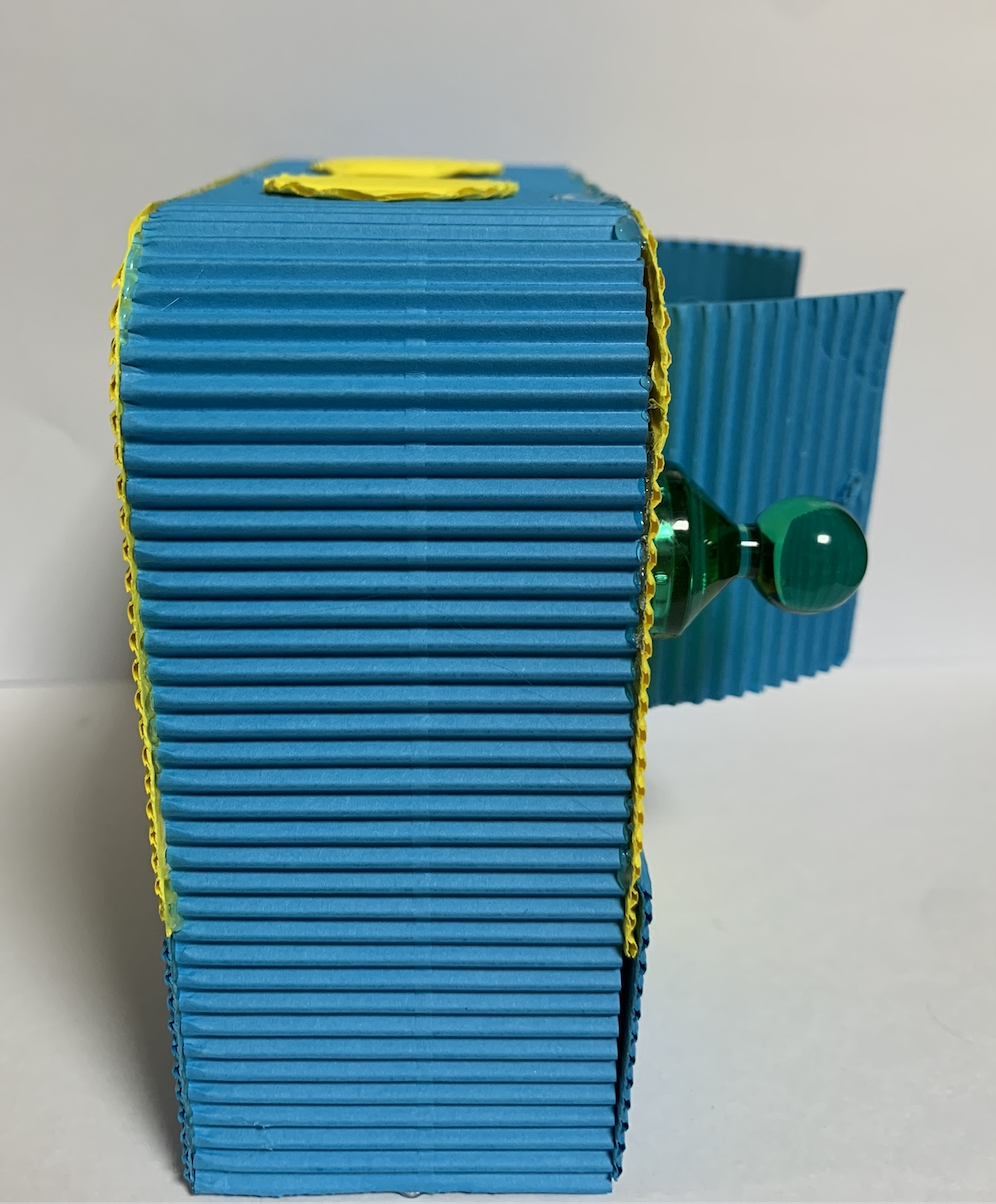
A side view of the controller unit crafted prototype
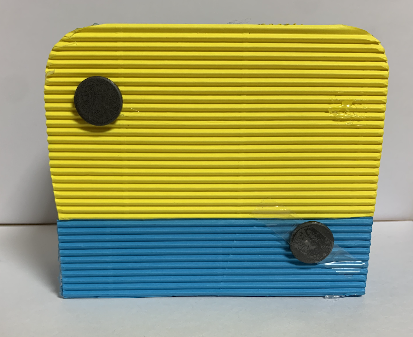
A back view of the controller unit crafted prototype (magnets for the convenience of installing it on the fridge)
A video of how the cuckoo bird clock-like notification works like
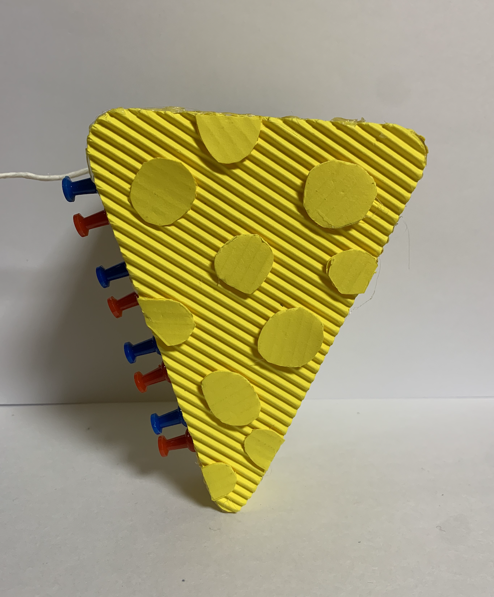
A front view of the sensor unit crafted prototype (cheese shape for entertainment)
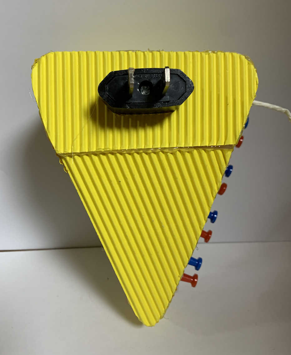
A back view of the sensor unit crafted prototype (a plug is directed connected to the unit)
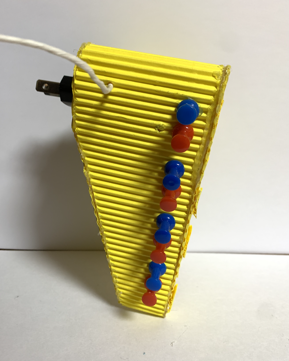
A side view of the sensor unit crafted prototype (blue and red pins represent IR proximity sensors that will be installed toward the fridge)
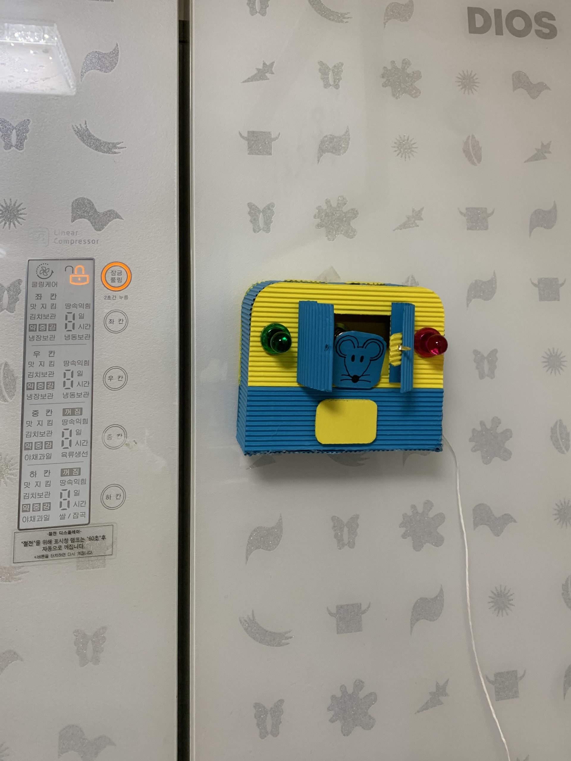
How the controller unit would look like when it is installed on the fridge
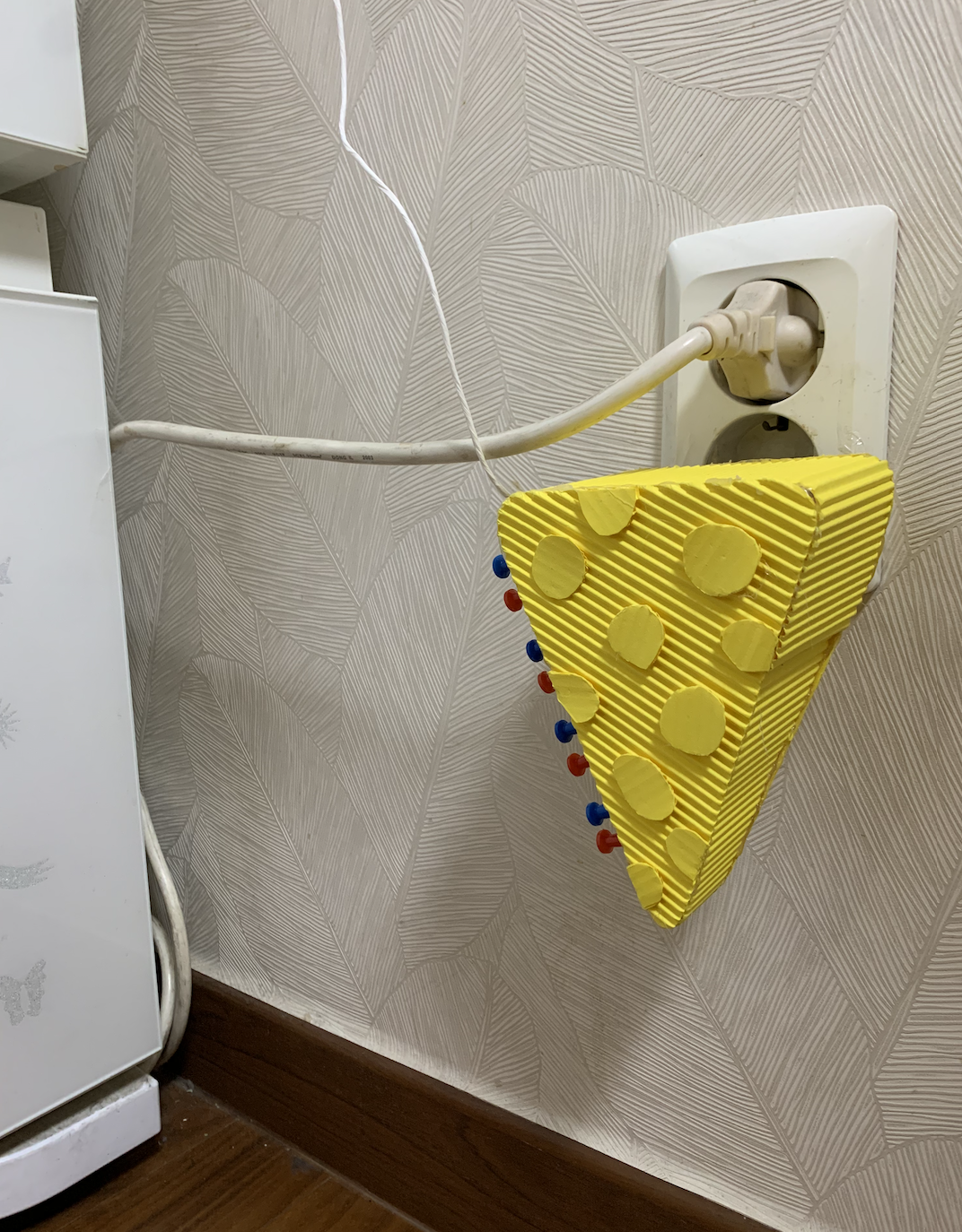
How the sensor unit looks like when it is plugged into an outlet (sensors are facing toward the fridge where Emily said mouse appear the most at her house)
NARRATIVE SKETCH
While Emily is at home, a mouse appears from behind the fridge, as usual. As soon as the detector that is plugged into the outlet by the fridge detects the moving mouse, the control panel above on the side of the fridge glows. The fun music plays, and the mouse character pops out of the small doors on the control panel. The sound wouldn’t go off at night, but since it’s daytime and Emily is awake, she needs to come to the fridge and press the reset button to stop the notification. She then calls her son to come into the house and for his cat to catch the mouse as soon as possible.
How We Got Here
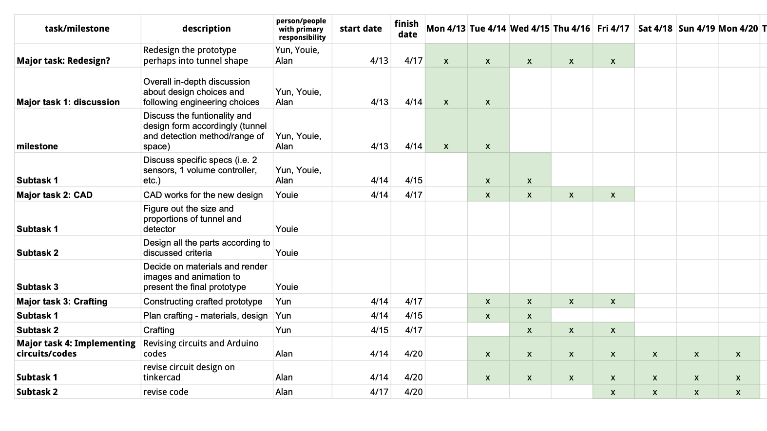
Our original schedule
When we were finalizing mechanism methods and components, we took some more time than we had planned in our work plan. This was because when we made the original schedule, we did not anticipate making such a big change in the final product. Although we spent more time in brainstorming and revising out design, the schedule worked out smoothly in the end, it took us less time to build the actual prototypes because the discussion we had earlier was very detailed.
Our prototype was a single-component mouse detector near the ground, with both the detection, control and notification functionalities. However, although a single-component device might be easy to use, we realized having both controller knobs and reset button near the floor would be inconvenient and dangerous for Emily whose back hurts when she bends her back and stands up. On top of that, we found it more visible to have notifications on our eye level rather than having it on the floor, and especially near the fridge where Emily consistently passes by and uses. After our in-depth discussion about the project, we decided to have two components—a sensor unit near the floor and a controller unit on the fridge—in our final product. We first took some time to figure out how they would be powered, and also how they would be connected to each other. Later we essentially redesigned our 3D models, and later built a physical mockup and a corresponding Tinkercad circuit.
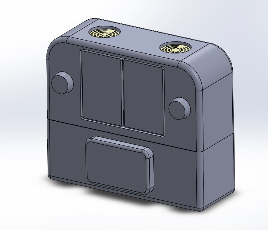
A front overview of the digital rendering draft
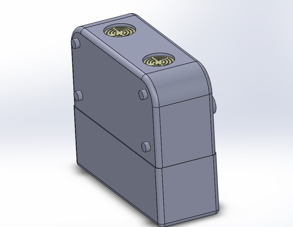
A back overview of the digital rendering draft
For designing the appearance and creating digital renderings, the main components within the control panel unit were kept as they were developed early on, including 2 speakers, 2 knobs, a pair of doors, 1 character panel, 1 reset button, and magnets on the back side. Since the very first iterations, the form was modified to give a soft and fun look, and knobs were made taller for better usability. The number of magnets was increased for them to be distributed more evenly and for sturdiness.
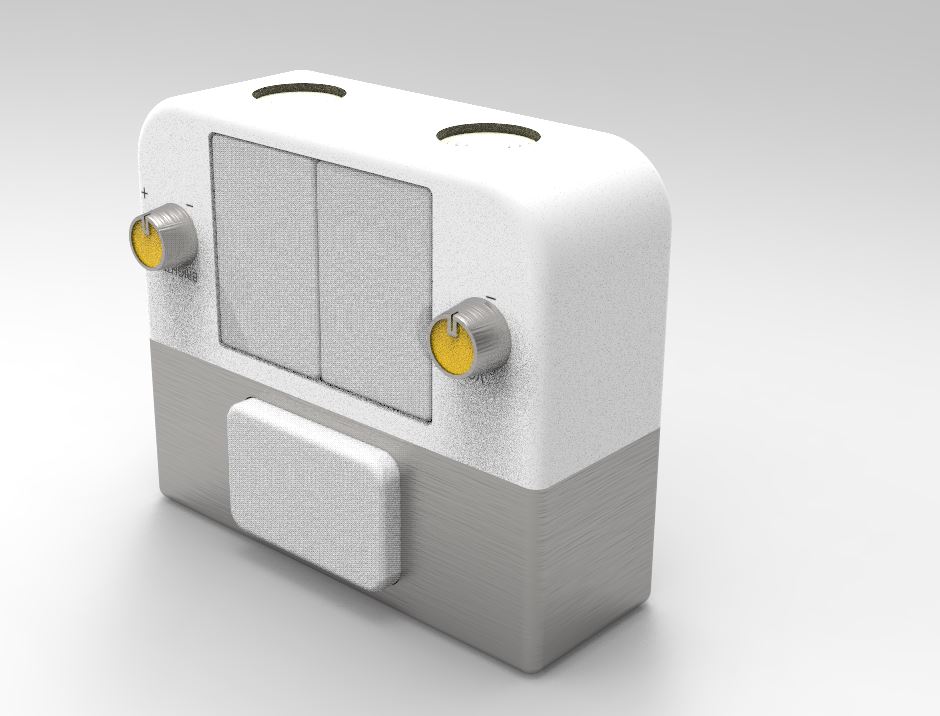
A front overview of the digital rendering draft with material details added
Then, we changed from a simple opaque material to a yellow, semi-transparent material to make it seem less serene or too much like a common house appliance, and more fun, as well as being able to transmit light when the notification light turns on. Towards the end, we learned that it actually takes a very long time to render transparent material, so we had some difficulty in producing high-quality light-on renders. We could have allocated more time to make this part go more smoothly.
We also used metal to clearly distinguish knobs to be interacted with and the bottom unit, which would contain any internal parts. We also added texture (texts layered on the front surface) to indicate what the knobs are and how to use them.
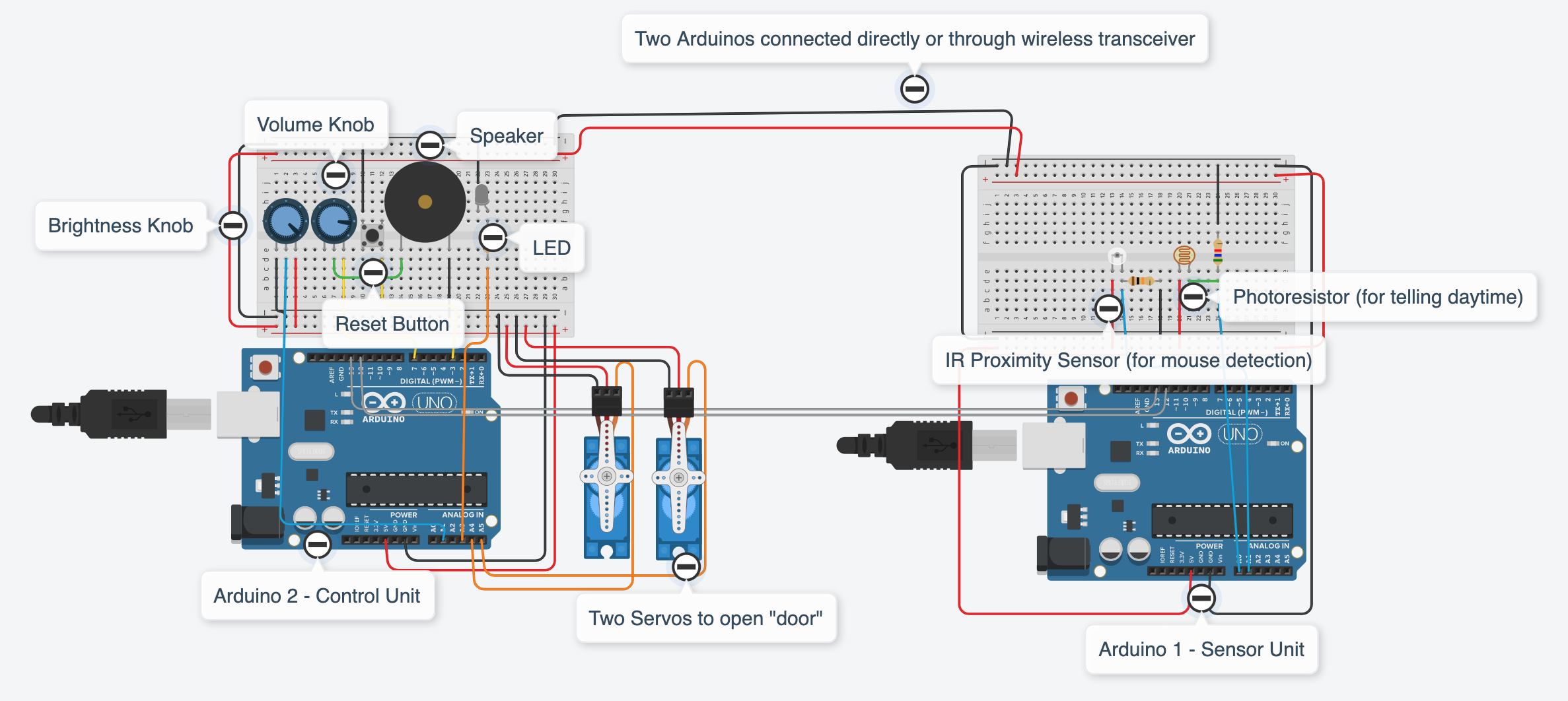
Electronically, we decided to power the detector part by plugging in to the outlet, and the control panel part by a USB cable from the outlet, after the hearing from Emily that she wanted them to powered by wall power. The two parts would wirelessly communicate through radio transceivers attached to the two Arduinos. However, since Tinkercad does not have the radio transceiver part, in our Tinkercad simulation the two Arduinos are directly connected by wires with two I/O pins, since the communication was simple enough. Another change from our original prototype was changing the sensor component from a PIR sensor to an IR proximity sensor, after feedbacks from our instructor Zach. Since Tinkercad does not have the part, we used an ambient light sensor to model the IR proximity sensor component.
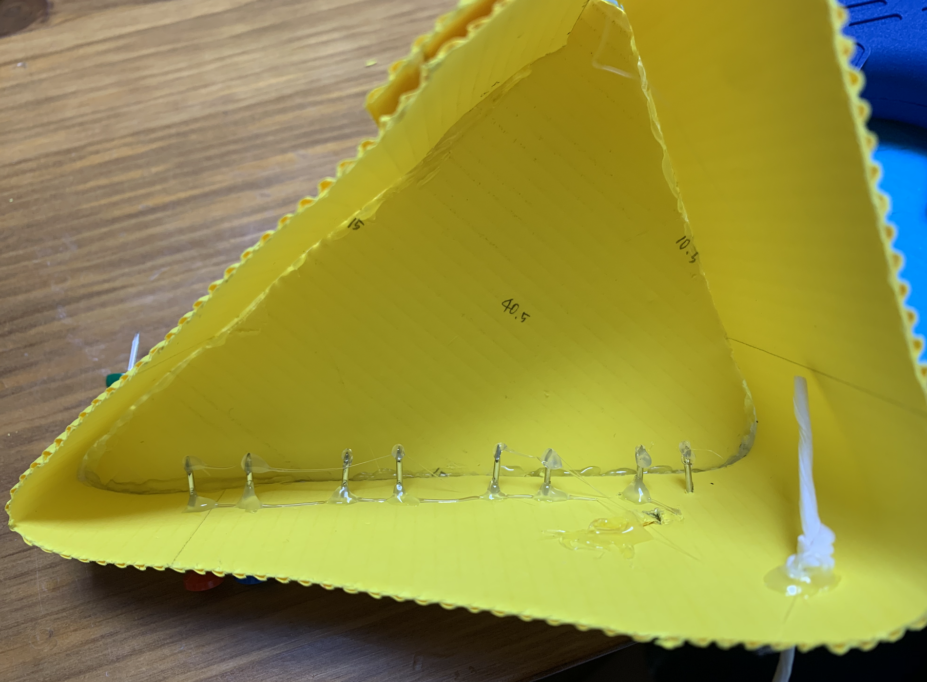
The interior of the sensor unit. There are multiple head pins which the end are hot-glued
For crafting, the hardest part was deciding which materials to use. Because we are not testing the whether the device actually works, the most important aspect of these materials were how easy it is to craft, and how close can it reflect our design. Due to the pandemic, there were some limitations in getting materials. We used corrugated cardboards for the general structure, stamp-looking fridge magnets for controller knobs, and two different colors of plastic head push pins which each represents IR receiver and IR emitter LED. However, using push pins were quite dangerous because the end parts are very sharp. For safety reasons only, we needed to hot-glue the end part although these details were not necessary.
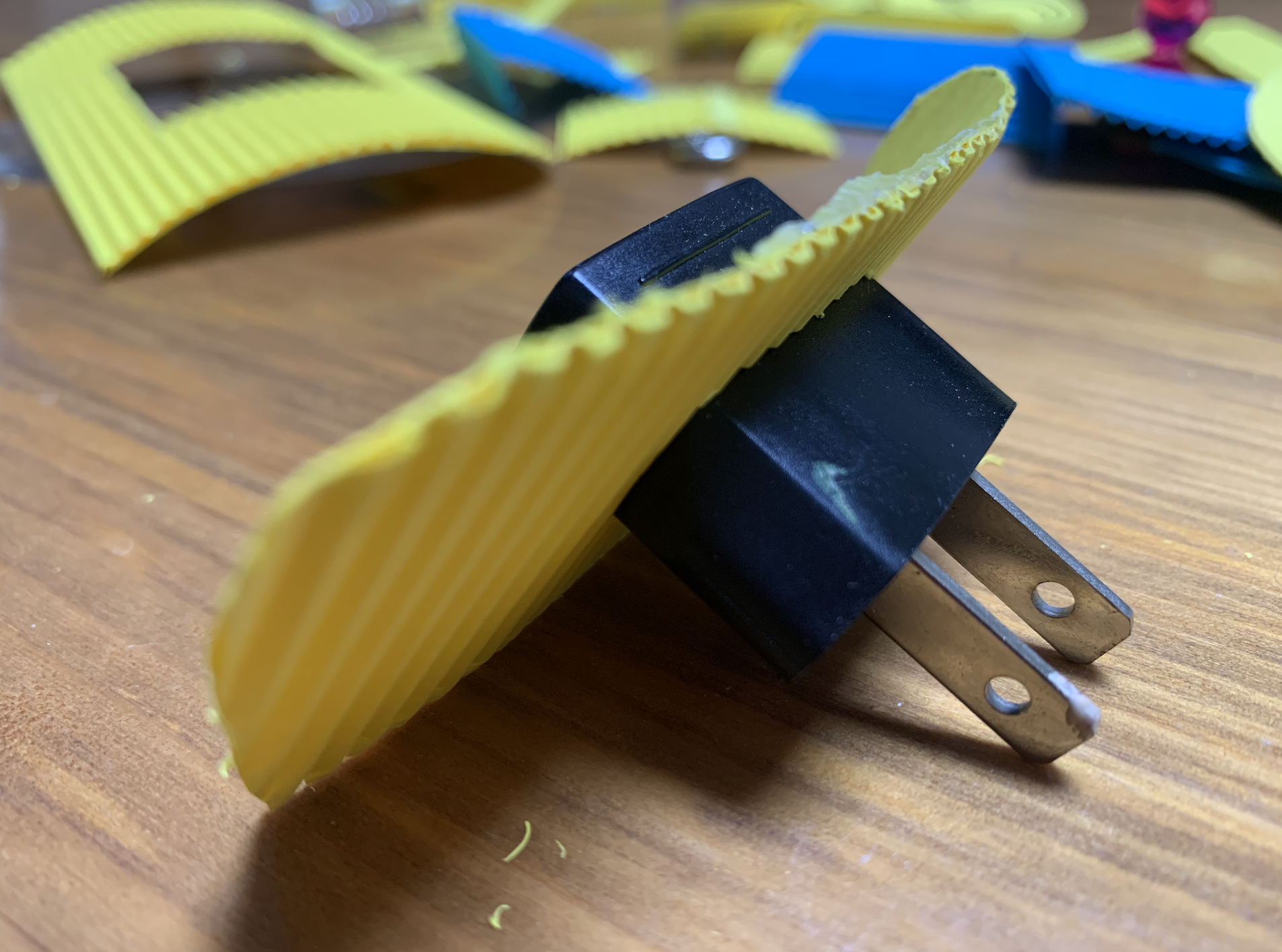
The connection between the appropriate size plug and the sensor unit
On top of that, there were some difficulties finding an appropriate size and weight of a plug connected to the sensor unit. If we had a chance to implement our design in the lab, this would not have be an issue; however, as we used a cardboard to make the body structure of the sensor unit, when the plug was too big and heavy, the structure collapsed. After multiple candidates, we found the plug that fits the sensor unit size and also not too heavy so that the craft can maintain its shape.
4. Conclusions and lessons Learned
During the final critique, we got multiple positive feedbacks about dividing the device into two parts, which was very rewarding because brainstorming and refining the idea was one of the biggest challenges in our project.
However, some feedback raised the concern about how accurate the sensor unit will be. Given the current situation, it is difficult to physically test, but we could have done some more research to predict better what the optimal angle or area size would be for the specific type and number of detectors. Moreover, in the normal lab setting, it would be hard to test it actually with mouse present; thus, if we were to test it in the lab, we would need to come up with a valid alternative testing method.
One feedback we got was that the novelty and entertainment components of this product might wear out. We think that this is definitely a valid feedback, but we think adding the fun part (the “cuckoo clock” notification) makes designing the product a bit more interesting compared to a simpler design. If we had more time, adding a function to change the alarm sound would make interacting with the product more interesting, and avoids the possibility that the user get annoyed by the alarm sound after using it for a while.
On top of that, during the feedback session with the final crafted prototype, there was a feedback that it would be better to have an on/off switch and a switch that can manually set the day and night mode. We had a discussion about adding such features, but ended up concluding that it is more important to make the device more concise and small as Emily requested it to be than to add additional features. However, there was a feedback during the final presentation suggesting an idea or merging volume and brightness knobs into one, which we have not thought of but seems very interesting and doable. If we have further opportunities to develop this device, we would like to further discuss about this point.
Regarding the teamwork, because our team members were working remotely from each other in different countries, it was difficult to share progress and iterations, and communication was often rather simplified. This made it a little harder to put together ideas and developments, so we decided that it would be the best if each person having a focus, and the process of discussing as a group first, building our own parts/prototypes, discussing our individual decisions and potential changes, and revising our parts. This worked fairly well as we could each take an ample amount of time to develop diverse prototypes, and take good feedback from each other.
Working with a client itself was definitely new to us but very valuable. Unlike following instructions or making a device for myself which were two prior projects conducted during the course, making a device for a person that I have never met before taught me how to interact with clients and how to get to know the client personally. Most importantly, we realized there were many considerations and assumptions we made without thorough decision making processes when we were doing a project on ourselves. For example, it would have been obvious to make the device installed on the desk without any question even just by imagining how we would use it, because that is where we go often; but it was not for Emily. We learned how to interview clients and to what extent we should be interviewing the client in terms of details, and in many cases interviewing the client life pattern turns out to be useful although it does not seem to be related to the project in the beginning.
We were so fortunate to have Emily, who is not only so warm and nice but also was very engaged in project such by giving objective feedbacks and her own ideas, as our client. She was also so opened in giving many small details about her life in general, which helped us a lot in constructively building the model. It truly made the virtual process a lot easier and more productive. However, we could have met her a couple more times to ask her for feedback and take some opportunities to gain more insights, reactions, and any recommendations. During this process, we also learned a little bit about what are some things to consider when designing for older people, such as the terms we use to describe their actions or needs, or keeping in mind their physical capabilities and limitations.
Technical Details
Tinkercad Link
Breadboard Image
Code for the sensor unit’s Arduino
/*
 * Final Project: Mouse Detector for Emily
 * Youie Cho, Yun Lee, Alan Zhu
 *
 * Description: This is the code that would be on the sensor unit's
 * Arduino. Essentially it reads an input of a IR Proximity sensor
 * (modeled by a phototransistor in Tinkercad) to check if a mouse
 * is nearby. If a mouse is detected, it sends a digital signal to
 * the control unit's Arduino. It also reads a photoresistor to
 * identify if it is daytime, and sends the digial signal to the
 * control unit.
 *
 * Pin mapping:
 * pin   | mode   | description
 * ------|--------|------------
 * A0     input    phototransistor (modeling a IR Proximity sensor)
 * A1     input    photoresistor
 * 12     output   direct digital output to the control unit
 * 13     output   direct digital output to the control unit
 *
 */

//input pins
const int PHOTOTRANSISTOR_PIN = A1;
const int PHOTORESISTOR_PIN = A0;

//output pins, both send signals to the control panel arduino
const int MOUSE_PIN = 13;
const int DAYTIME_PIN = 12;

int lightLimit = 650;
int mouseLimit = 900;
int lightVal, mouseVal;

void setup()
{
  Serial.begin(9600);
  pinMode(PHOTOTRANSISTOR_PIN, INPUT);
  pinMode(PHOTORESISTOR_PIN, INPUT);
  pinMode(MOUSE_PIN, OUTPUT);
  pinMode(DAYTIME_PIN, OUTPUT);
}

void loop()
{
  //Reads photoresistor, if the readings exceed the preset limit,
  //it is daytime. Sends corresponding digital signal to the control
  //panel Arduino.
  lightVal = analogRead(PHOTORESISTOR_PIN);
  if(lightVal >= lightLimit) digitalWrite(DAYTIME_PIN, HIGH);
  else digitalWrite(DAYTIME_PIN, LOW);

  //Reads phototransistor value (modeling IR Proximity Sensor),
  //if exceeds preset limit, mouse is detected. Sends corresponding
  //digital signal to the control panel Arduino.
  mouseVal = analogRead(PHOTOTRANSISTOR_PIN);
  if(mouseVal >= mouseLimit) digitalWrite(MOUSE_PIN, HIGH);
  else digitalWrite(MOUSE_PIN, LOW);

  delay(150);
}
Code for the control panel unit’s Arduino
/*
 * Final Project: Mouse Detector for Emily
 * Youie Cho, Yun Lee, Alan Zhu
 *
 * Description: This is the code that would be on the control panel
 * unit's Arduino. It reads the inputs from the sensor unit's Arduino
 * of whether a mouse has been detected and if it is daytime. If a mouse
 * is detected, the LED lights up, two servomotors rotate to open a
 * door. The speaker plays music in addition if it is daytime. The brightness
 * knob potentiometer sets the brightness level for the LED, and the volume
 * knob sets the loudness of the speaker. If the reset button is pressed,
 * the LED turns off, two servomotors return to its original position and
 * closes the door, and the music is turned off.
 *
 * Pin mapping:
 * pin   | mode   | description
 * ------|--------|------------
 * A1     input    potentiometer (brightness knob)
 * A3     output   LED
 * A4     output   servo 1
 * A5     output   servo 2
 * 3	  input    reset button
 * 7      output   piezo speaker
 * 12     input    direct digital input from the sensor unit Arduino
 * 13     input    direct digital input from the sensor unit Arduino
 *
 */

#include <Servo.h>

Servo servo1, servo2;

//input pins
const int MOUSE_PIN = 13; // from the other Arduino
const int DAYTIME_PIN = 12; // from the other Arduino
const int LIGHT_POT_PIN = A1;
const int BUTTON_PIN = 3;

//output pins
const int PIEZO_PIN = 7;
const int LED_PIN = A3;
const int SERVO1_PIN = A4;
const int SERVO2_PIN = A5;

int photoLimit, photoVal, lightVal;
bool dayTime, mouse, button;

void setup()
{
  Serial.begin(9600);
  servo1.attach(SERVO1_PIN);
  servo1.write(0);
  servo2.attach(SERVO2_PIN);
  servo2.write(180);
  pinMode(MOUSE_PIN, INPUT);
  pinMode(DAYTIME_PIN, INPUT);
  pinMode(LIGHT_POT_PIN, INPUT);
  pinMode(BUTTON_PIN, INPUT_PULLUP);
  pinMode(PIEZO_PIN, OUTPUT);
  pinMode(LED_PIN, OUTPUT);

}

void loop()
{
  //read the brightness knob to set brigtness level for LED
  lightVal = map(analogRead(LIGHT_POT_PIN), 0, 1023, 0, 255);

  //receive from the mouse detector arduino if mouse is detected
  mouse = digitalRead(MOUSE_PIN);

  //receive from the mouse detector arduino if it is daytime
  dayTime = digitalRead(DAYTIME_PIN);

  //read if reset button is pressed
  button = digitalRead(BUTTON_PIN);

  //If mouse is detected, turn on light
  //and turn the two servos to open the doors
  if(mouse) {
    analogWrite(LED_PIN, lightVal);
    servo1.write(45);
    servo2.write(135);
  	Serial.println("Mouse detected!!");
    if(dayTime) playMusic(); //only play music if it is daytime
  }

  //If reset button pressed, turn off light and music,
  //and reset the servos back to its original position
  if(!button) {
    analogWrite(LED_PIN, 0);
    noTone(PIEZO_PIN);
    servo1.write(0);
    servo2.write(180);
    mouse = false;
    Serial.println("Reset");
  }

  delay(100);
}

//play a tune on the speaker
void playMusic()
{
  tone(PIEZO_PIN, 600, 150);
  delay(150);
  tone(PIEZO_PIN, 800, 150);
  delay(150);
  tone(PIEZO_PIN, 1000, 150);
  delay(150);
  tone(PIEZO_PIN, 1200, 150);
  delay(350);
}
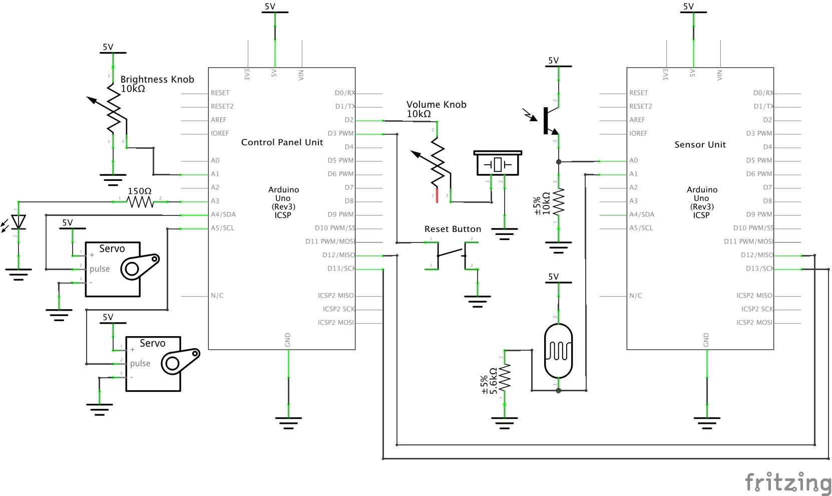
Schematic
Design Files
Comments are closed.