
Simple narrative description
When the dial turns fast, the LED gets brighter. When the LED gets brighter, the light sensor pushes more electricity into the system. When there is more electricity in the system, the motor blade turns closer to the edge of the board. Since the magnet is attached to the motor blade, it also moves closer to the edge of the board, creating a stronger magnetic field.
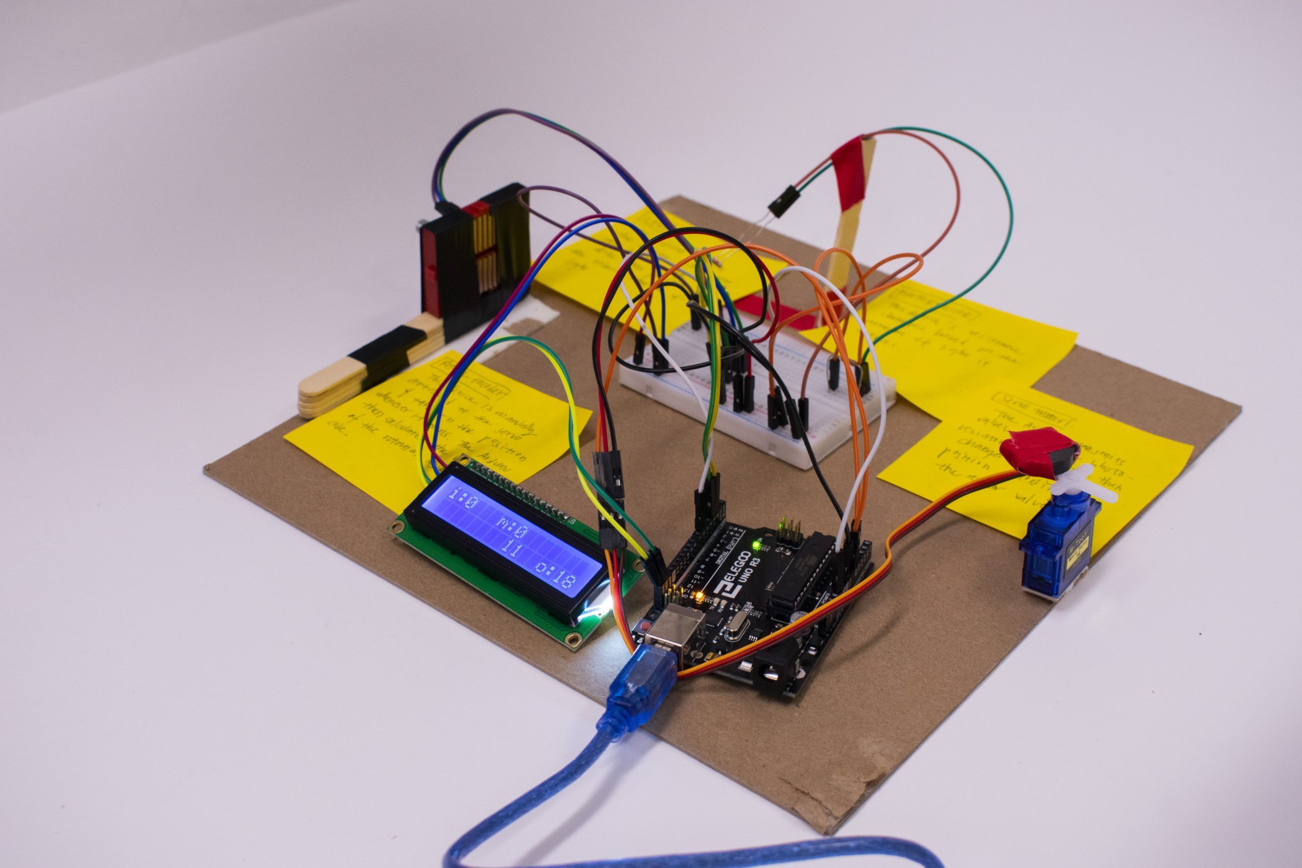
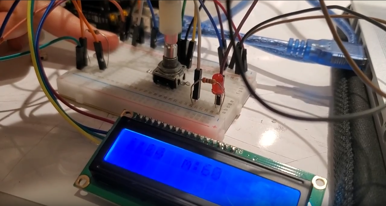
Overall project mounted onto a 10’’ by 10’’ chipboard.
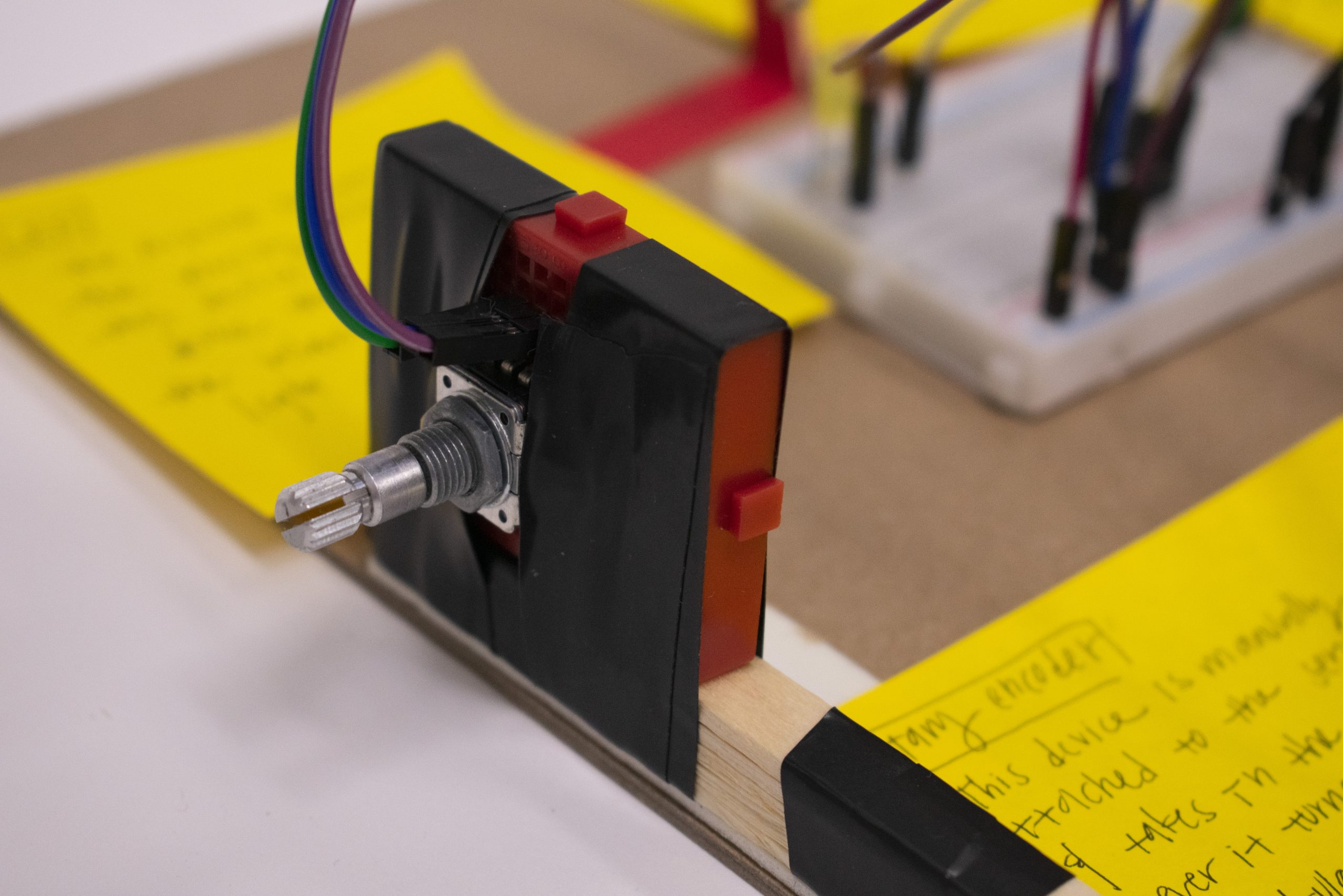
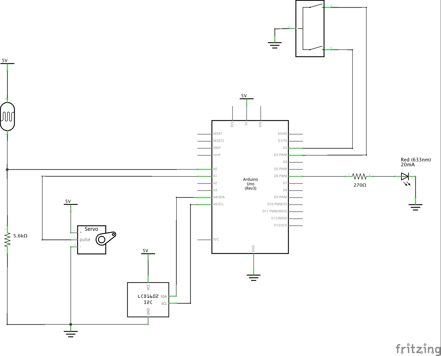
ROTARY ENCODER: This device is manually attached to the ervo and takes in the position whenever it turns. The Arduino then calculates the velocity of the rotation inside the code.
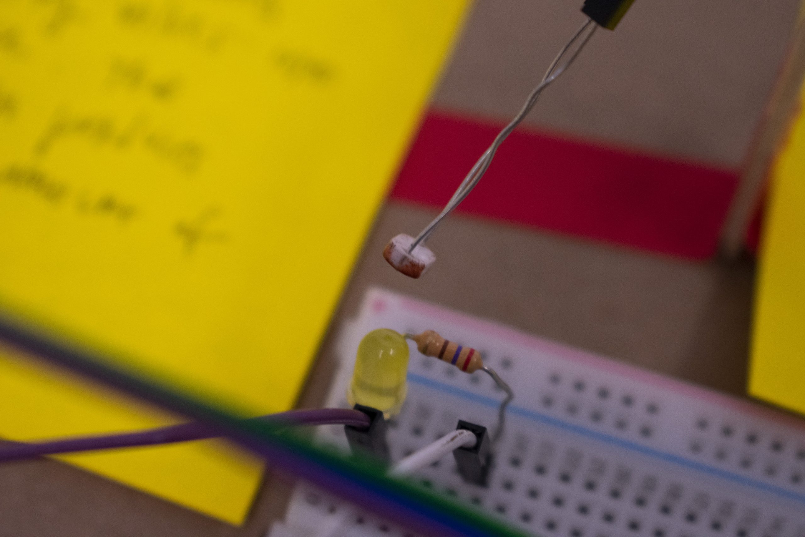
LED + PHOTORESITOR The Arduino transmits the velocity values into the LED. The LED then produces the relative amount of light. The photoresitor’s resistance then changes based on the amount of light detected from the LED.
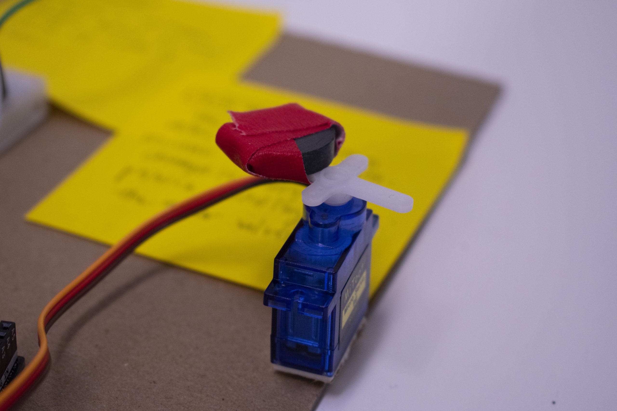
SERVO MOTOR: The Arduino transmits values from the photoresistor. This device then changes its degree position according to the resistor values.
Three progress images
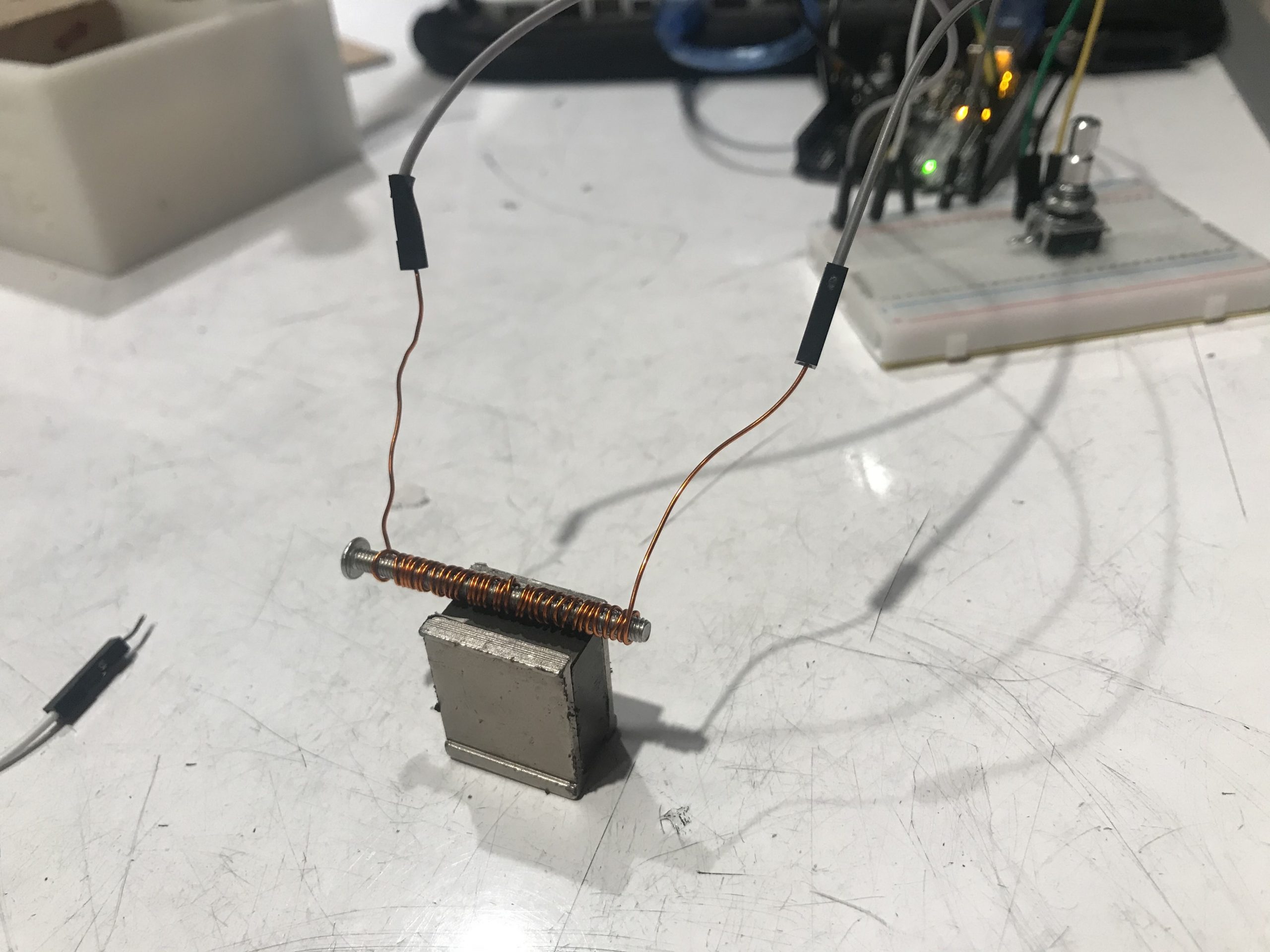
Initially, we tried to pass current through a coil that contained a nail. It was difficult to read the magnetic output from this setup, so we eventually scrapped it.
We tested a magnet wrapped with a coil and struggled to detect magnetic field changes when we powered the coil.
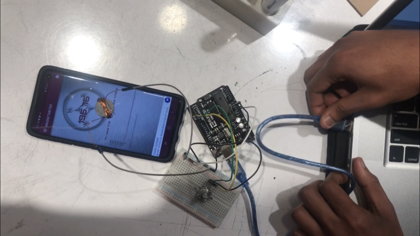
At this stage, we could read the motor speed, but the LED was not properly responding to PWM commands.
Discussion
Designing the overall system was relatively easy, as there was little ambiguity in understanding the high level overview of how data is translated from one transducer to the other. However, debugging unexpected errors that came up in every step of the “building” process required us to think of the problem from multiple angles. For instance, when we first worked with the rotary encoder, the position values inputted into the Arduino were not timely enough to calculate the rotation speed. Only after editing the velocity formula, scouring through the web for other methods to read rotation speed, and rechecking the circuit for any errors, we found out our solution through careful reading of the library documentation: input pins should be plugged into pins with interrupt capability for optimal performance. Such finding was only possible by giving ourselves enough time and flexibility to understand the mishap from multiple angles, rather than falling into a state of panic with no clear solution in mind.
The biggest learning from this project was that the root of certain problems often come from places that we weren’t even aware of. For instance, our photoresistor and LCD display gave erroneous values that simply did not comply with the system that we had built up. We gave bandaid solutions to these problems by fixing the range of each input on the software, which helped little in tackling the issue. However, we realized after talking to Zach that the issue was caused by the photoresistor pin being plugged into the same circuit as the LCD Display (A4, which is connected to SVA/SCL). At that point, we were both frustrated that such a seemingly small issue had caused us such a big struggle. However, I am glad that we encountered the issue through this project, as the connection of SVA/SCL to A4/A5 will forever be embedded in our memories for future projects to come.
Overall, creative problem solving was critical to the success of the project. Iterating upon each step in a bite sized manner, rather than building up the whole circuit first and trying to understand where the problem points were, allowed us to develop thoughtful problem solving skills. While this project took a much longer time than we had initially anticipated, I hope this sets a good foundation for next projects to be more smooth sailing.
Schematic
Code
/*
 * Project 1: Rotation speed --> LED brightness --> magnetic field strength
 * Abel Tesfaye (atesfaye) and Elizabeth Han (yoonjuh)
 *
 * Collaboration: We used some code from the sample encoder library
 * to figure out how to read the rotary encoder position.
 *
 * Challenge: We accidentally used A4/A5 while we had the display
 * plugged into SVA/SCL. This caused weird interactions because A4 is wired to SVA
 * and A5 is wired to SCL.
 *
 * Next time: We will be more careful about which pins we are using on the
 * arduino
 *
 * Description: This code reads the rotary encoder input position and calculates the speed
 * of the turning encoder head. It also converts the speed into the brightness value
 * for the led. It then reads the led brightness value
 * with a photoresistor. The code also filters the detected brightness to make it
 * more smooth. Finally, the filitered brightness is mapped to the hobby motor such
 * that higher brightness means more motor turning. The main loop runs 10 times a second.
 * The LCD screen is updated twice a second.
 *
 * Pin mapping:
 *
 * pin   | mode   | description
 * ------|--------|------------
 * 2      input     rotary encoder input 1
 * 3      input     rotary encoder input 2
 * 6      output    led output
 * A0     input     photoreistor input pin
 * A1     output    servo output pin
 * SDA    output    LCD display pin
 * SCL    output    LCD display pin
 *
 */

#include <Encoder.h>
#include <Wire.h>
#include <Servo.h>
#include <LiquidCrystal_I2C.h>

Encoder myEnc(2, 3);

LiquidCrystal_I2C screen(0x27, 16, 2);

Servo myLittleMotor;

const int LEDPIN = 6;
const int PHOTORESITORPIN = A0;
const int SERVOTPIN = A1;

long oldPosition  = -999;
unsigned long timer = 0; // variable for timing
const int INTERVAL = 500; // milliseconds between updates

const float PREV_WEIGHT = 0.8;
const float CUR_WEIGHT = 1 - PREV_WEIGHT;
float filtered_brightness = 0;

void setup() {
  Serial.begin(9600);
  Wire.begin();
  screen.init();
  screen.backlight();

  pinMode(PHOTORESITORPIN, INPUT);

  myLittleMotor.attach(SERVOTPIN);
}

void loop() {
  long newPosition = myEnc.read();

  float speed = abs(newPosition - oldPosition) / .01;
  //cap speed at 9000
  if(speed > 9000) speed = 9000;

  int mappedSpeed = map(speed, 0, 9000, 0, 99);


  oldPosition = newPosition;

  int led = map(mappedSpeed, 0, 99, 0, 255);
  int mappedLed = map(led, 0, 255, 0, 99);

  analogWrite(LEDPIN, led);


  int brightness = analogRead(PHOTORESITORPIN);
  //filter/smooth the detected brightness value
  filtered_brightness = filtered_brightness * PREV_WEIGHT + brightness * CUR_WEIGHT;

  Serial.println(filtered_brightness);
  int mappedBrightness = map(filtered_brightness, 70, 255, 0, 99);
  int motor = map(mappedBrightness, 0, 60, 0, 180);
  int mappedMotor = map(motor, 0, 180, 0, 99);

  myLittleMotor.write(motor);

  if (millis() >= timer) {
    // set cursor to home position, i.e. the upper left corner
    screen.home();
    screen.clear();

    screen.print("i:");
    screen.print(mappedSpeed);

    screen.setCursor(6, 0);
    screen.print("m:");

    screen.print(mappedLed);
    screen.setCursor(8, 1);
    screen.print(mappedBrightness);
    screen.setCursor(12, 1);
    screen.print("o:");
    screen.print(mappedMotor);


    timer = millis() + INTERVAL; // and update timer
  }
  delay(100);
}
Comments are closed.