Overview
Project Explanation: This compact scooter turn signal device uses an on-off-on switch to display either blinking left or right arrows.
[Disclaimer: all process images and videos were unfortunately taken using my iPhone camera and could not be retaken do to the circumstances. Please excuse the poor quality or framing of the images, if possible.]
Video displaying the switch being used to toggle between the Left, Right, and Off mode.
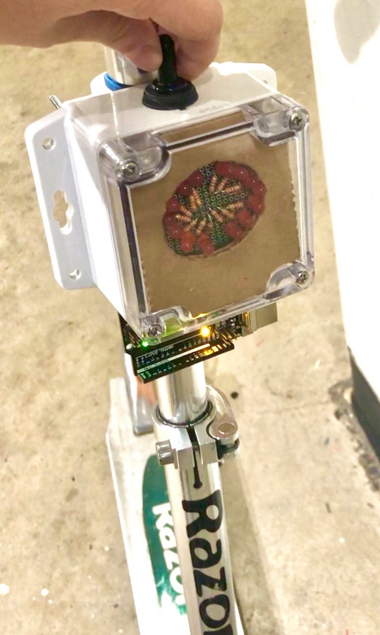
Overall photo for proportion and scale of turn signals device in relation to human hand and scooter.
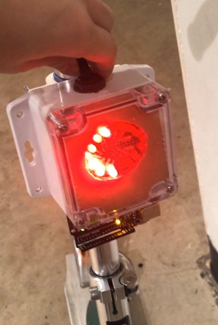
In the Left mode, when the switch is pushed to the left, the left set of LEDs blinks on and off in half-second intervals. The same applies for the Right mode.
Parts Highlighted
On-Off-On DPDT Switch
This On-Off-On DPDT switch has 3 of its 6 pins hooked up to the Arduino, 2 of them to 2 separate input pins and 1 of them to 5V. This switch allows the user to toggle between Left, Right, and Off mode.
Custom 3D-printed Clamp
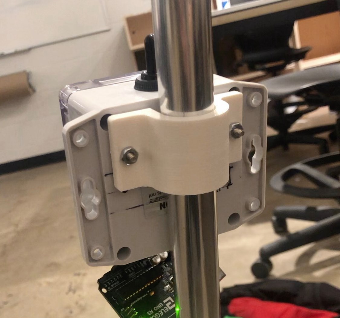
This 3D-printed clamp was custom-designed in Fusion360 in order to snugly fit around the vertical bar of the scooter and attach the device to the scooter.
DIY LED Matrix
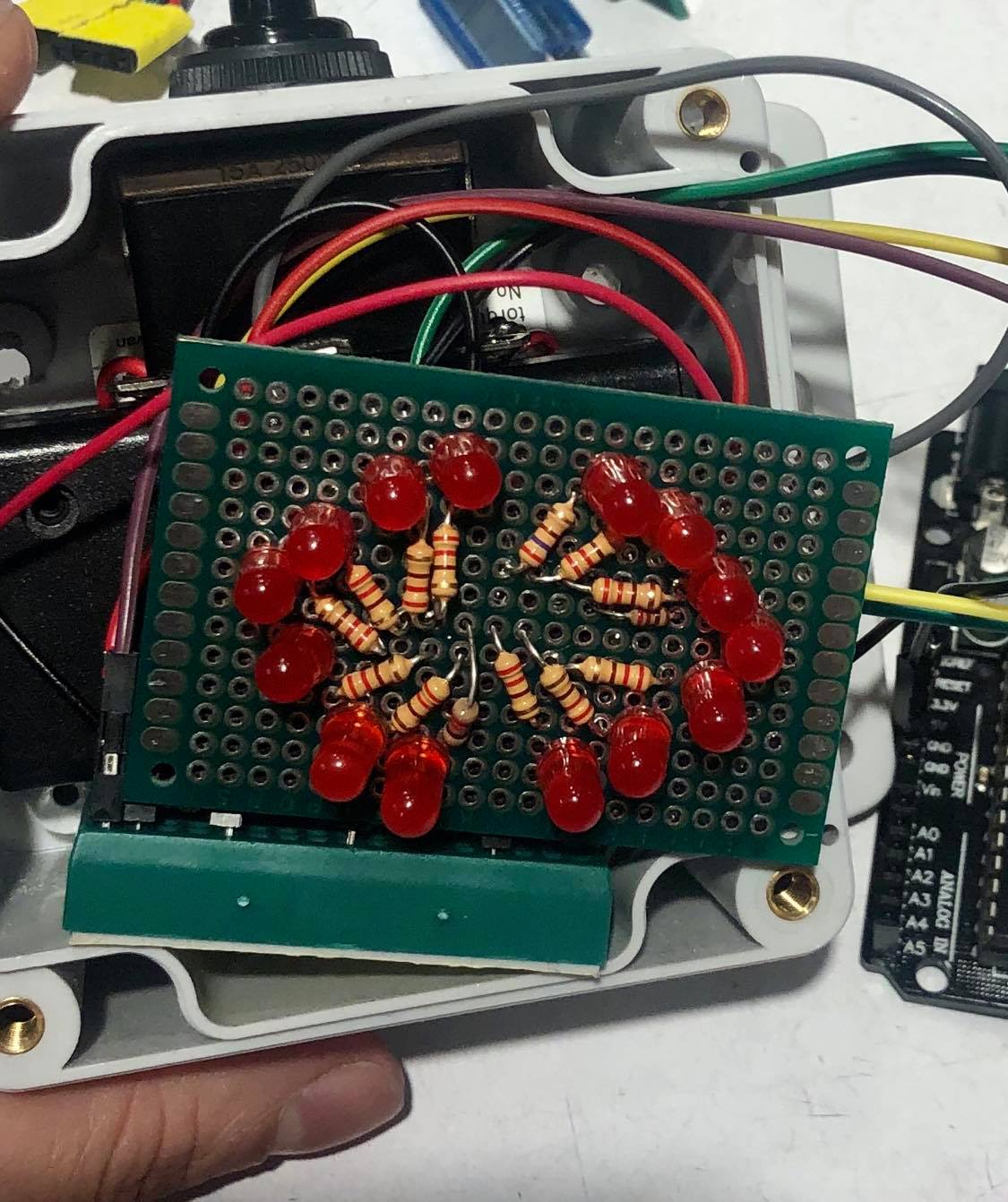
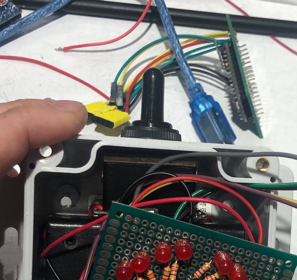
2 sets of 7 Red LEDs are connected to 2 sets of 7 220ohm resistors to form 2 separate sets of LEDs.
Images Showing the Turn Signals in Use
[Hoped to insert an image of the scooter being ridden outside with the turn signals in use but didn’t have access to device.]
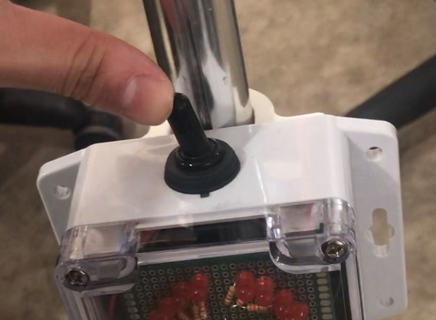
The switch allows the user to easily change the blinker between left blinker, right blinker, and off.
Process images and review
One of the main decision points I reached was choosing to use the Arduino Uno R3 instead of the Arduino Pro Mini. On the night before the critique, I managed to achieve a functional set-up of the device outside of the container using the Arduino Pro Mini, meaning the LED matrices responded properly to corresponding switch movements. However, after attempting to shove the components into the container, functionality ceased. I went into debugging mode and hooked up the Pro Mini to my computer to read Serial feedback. The Arduino Pro Mini had stopped correctly reading the digital inputs from the switch. I tried using different Arduino Pro Mini’s to no avail. On the cusp of giving up, my classmates proved to be an incredible source of encouragement, pushing me to continue with my project using the more reliable Arduino Uno R3 (while unfortunately sacrificing compactness in my design). The Arduino Uno R3 produced the proper Serial feedback for corresponding switch movements and I was able to proceed with my project.
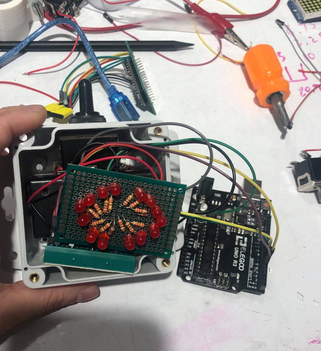
The larger, but more reliable, Arduino Uno R3 can be seen here hooked up to the device, in place of the Arduino Pro Mini.
Another significant decision point I encountered was choosing to create a DIY LED device instead of using two AdaFruit 8×8 LED Matrices. During the process of attempting to shove the components in the container, the Adafruit LED Matrices stopping illuminating in response to the switch movements. In trying to isolate the problematic components, I tested the LED Matrices individually using the Arduino Uno R3 and sample code provided by Adafruit (which previously worked as expected). I was dismayed to discover the matrices no longer worked. After a brief period of self-pity, my classmate, Zoe, was an invaluable resource in showing me how to hookup LEDs and resistors in parallel to create a set of LEDs! With her guidance, I was able to make a pseudo LED matrix consisting of two sets of 7 LEDs and 7 220 ohm resistors in the shape of left and right arrows on a protoboard. This component had surprising advantages in that it was much easier to code, brighter than the LED matrices, and took up less space in the container.
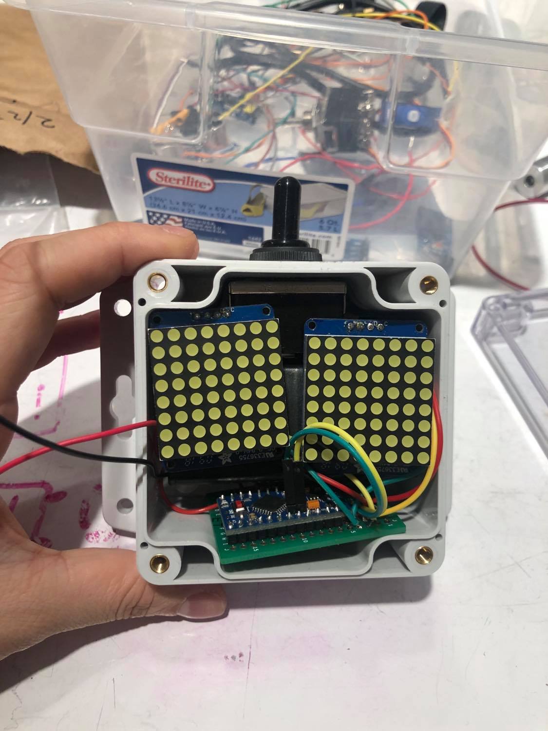
What the device would have looked like if I were to have used the Adafruit LED matrices, which unfortunately stopped responding to Arduino input.
Some aspects of my process I’d like to highlight are:
- 3D-modeling a custom scooter clamp part in Autodesk Fusion360…
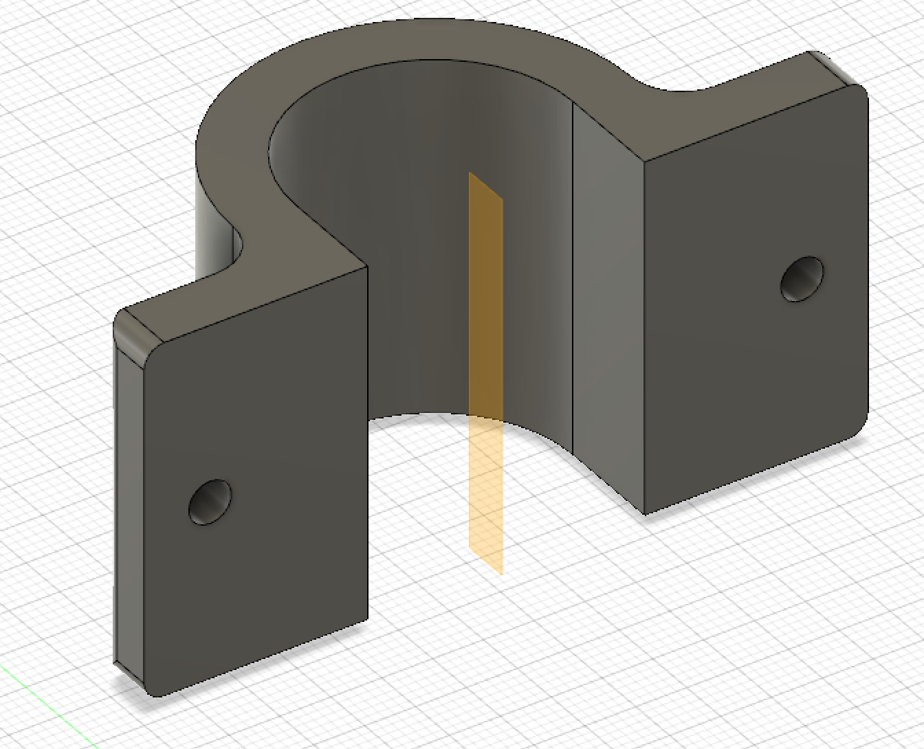
I created a 3D-model of the scooter clamp in Autodesk Fusion360.
- …and 3D-printing the part using IDeATe’s SkyLab service. Soaking the printed part in the chemical wash overnight and finding it with the screw hole filaments melted away was a particularly pleasant part of this process.
- Measuring the battery case and plastic container using a digital caliper and marking the container where to drill holes for the switch and battery switch.
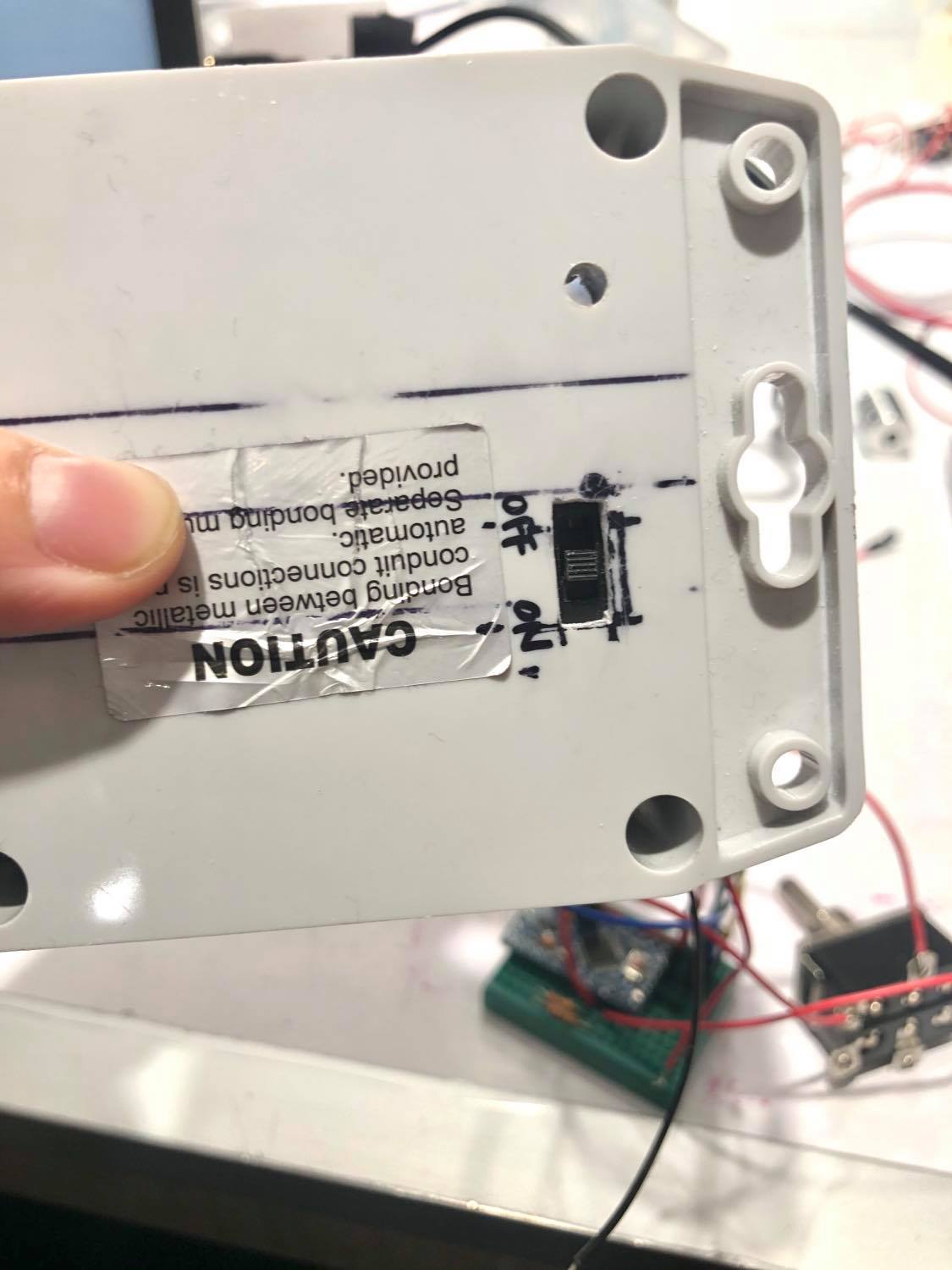
Precise measurements with a digital caliper and Sharpie marking on the container allowed me to accurately drill a hole for the battery switch.
Discussion
Through the in-class critique, I was able to gain some useful feedback on both the positive aspects of my device and the aspects which had room for improvement.
One critique stated they enjoyed the overall design but posited that “maybe the arrows could be different colors.” This touches on the topic of how to make the left and right signals more distinguishable from one another. The main ways I could have accomplished this was through distance, shape, or, as suggested, color. My current design attempts to take advantage of shape, where each signal is an arrow of LEDs pointing to the left or right. The downside of this design choice is that it may lack clarity from larger distances. Using color as a distinguisher, however, also has the downside of there not being a universally-accepted association between colors and direction. Colors are usually known to correlate with “stop/start”, which could be unintentionally confusing for oncoming pedestrians. I think improvements on the current design would be: 1) sharpen the LED arrowheads, and 2) as suggested by Zach, add a line of LEDs as a body for the arrowheads. This design change would hopefully make the signals more clearly arrows while keeping the design central and compact by not choosing distance as the distinguisher.
Another critique commented, “Looks nice. Moving the switch closer to the handlebar would make it perfect.” I completely agree with this critique! Thankfully, the position of the device on vertical scooter pole is adjustable and by simply sliding the clamp and the device up the pole, the switch can be positioned so it is very close to the handlebars, and thus, the hands.
Overall, I was pleasantly surprised by the positive reception of my turn signals during the critique! If I were to self-critique my project, my main point of disappointment would be the loss of being waterproof. Since the basic electronics and software of this device was fairly simple (involving only four components: switch, battery, Arduino, LEDs), one of my main focuses for this project was its design, in regards to both compactness and waterproof-ness. Using an Arduino Pro Mini, I was able to fit all the pieces into the case (albeit, quite snugly), but, unfortunately, I was unable to get the Arduino Pro Mini to consistently read the switch’s signals correctly. This forced me to go with the more reliable Arduino Uno R3 and, thus, compromise the waterproof feature of my device.
Although my project fell short in some aspects, I am enormously proud of the adjustments I was able to make throughout and definitely learned a lot about the engineering process.
Troubleshooting when the device didn’t work was one of the hardest parts of this process. After getting the switch and LED matrices to successfully work together on the Arduino Uno R3 and the Arduino Pro Mini using a breadboard, I made the mistake of sautering on all the parts to a protoboard at once and then finding out that the LED matrices were no longer turning on. I learned that in the future, I should take on a much more iterative approach, especially when it comes to steps that are hard to reverse, like sautering. This oversight cost me a lot of time, having to go back and forth between the Uno R3 and Pro Mini while trying out countless different combinations of switches, wires, pins, and matrices.
Another thing I learned was that I really enjoyed the fabrication process! I had a lot of fun 3D printing the custom clamp piece for the scooter, as well as drilling precise holes into the case for the switch and power switch. I felt I had more control and awareness of what I was doing when customizing the materials, as opposed to when dealing with the somewhat mysterious world of electronics.
If I were to build another iteration of my turn signals, I would take another stab at making the device waterproof by using the Arduino Pro Mini and a protoboard, making sure to test one component at a time after sautering. Some interesting additional features to add to the device would be: a) a third mode which blinks both lights, to simply act as lights for night time “scooting” and b) a charging port for the battery.
Technical information
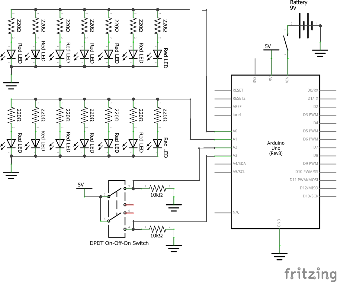
Schematic of the Turn Signals deivce
- <span class="com">/*
- Project Title: Scooter Turn Signals
- Names: Sue Lee
- Description: The code reads the digital values of the pins for the
- left and right switch positions. A HIGH digital value of the left and right pin initiates
- the left and right LEDs, respectively, to turn on for .5 sec and off for .5 sec.
- Pin mapping:
- pin | mode | description
- ------|--------|------------
- A3 input Switch Left Position
- A2 input Switch Right Position
- A1 output Left LED Arrow
- A0 output Right LED Arrow
- Credit: None
- License Notice:
- Copyright 2020 Sue Lee
- Permission is hereby granted, free of charge, to any person obtaining
- a copy of this software and associated documentation files (the "Software"),
- to deal in the Software without restriction, including without limitation
- the rights to use, copy, modify, merge, publish, distribute, sublicense,
- and/or sell copies of the Software, and to permit persons to whom the
- Software is furnished to do so, subject to the following conditions:
- The above copyright notice and this permission notice shall be included in
- all copies or substantial portions of the Software.
- THE SOFTWARE IS PROVIDED "AS IS", WITHOUT WARRANTY OF ANY KIND, EXPRESS OR
- IMPLIED, INCLUDING BUT NOT LIMITED TO THE WARRANTIES OF MERCHANTABILITY,
- FITNESS FOR A PARTICULAR PURPOSE AND NONINFRINGEMENT. IN NO EVENT SHALL
- THE AUTHORS OR COPYRIGHT HOLDERS BE LIABLE FOR ANY CLAIM, DAMAGES OR OTHER
- LIABILITY, WHETHER IN AN ACTION OF CONTRACT, TORT OR OTHERWISE, ARISING FROM,
- OUT OF OR IN CONNECTION WITH THE SOFTWARE OR THE USE OR OTHER DEALINGS IN THE
- SOFTWARE.
- */</span><span class="pln">
- </span><span class="com">#define</span><span class="pln"> SWITCHL_PIN A3
- </span><span class="com">#define</span><span class="pln"> SWITCHR_PIN A2
- </span><span class="com">#define</span><span class="pln"> LED_LEFT_PIN A1
- </span><span class="com">#define</span><span class="pln"> LED_RIGHT_PIN A0
- </span><span class="kwd">void</span><span class="pln"> setup</span><span class="pun">()</span><span class="pln"> </span><span class="pun">{</span><span class="pln">
- </span><span class="typ">Serial</span><span class="pun">.</span><span class="kwd">begin</span><span class="pun">(</span><span class="lit">9600</span><span class="pun">);</span><span class="pln">
- pinMode</span><span class="pun">(</span><span class="pln">SWITCHL_PIN</span><span class="pun">,</span><span class="pln"> INPUT</span><span class="pun">);</span><span class="pln">
- pinMode</span><span class="pun">(</span><span class="pln">SWITCHR_PIN</span><span class="pun">,</span><span class="pln"> INPUT</span><span class="pun">);</span><span class="pln">
- pinMode</span><span class="pun">(</span><span class="pln">LED_LEFT_PIN</span><span class="pun">,</span><span class="pln"> OUTPUT</span><span class="pun">);</span><span class="pln">
- pinMode</span><span class="pun">(</span><span class="pln">LED_RIGHT_PIN</span><span class="pun">,</span><span class="pln"> OUTPUT</span><span class="pun">);</span><span class="pln">
- </span><span class="pun">}</span><span class="pln">
- </span><span class="kwd">void</span><span class="pln"> loop</span><span class="pun">()</span><span class="pln"> </span><span class="pun">{</span><span class="pln">
- </span><span class="kwd">int</span><span class="pln"> leftSwitchState </span><span class="pun">=</span><span class="pln"> digitalRead</span><span class="pun">(</span><span class="pln">SWITCHL_PIN</span><span class="pun">);</span><span class="pln">
- </span><span class="kwd">int</span><span class="pln"> rightSwitchState </span><span class="pun">=</span><span class="pln"> digitalRead</span><span class="pun">(</span><span class="pln">SWITCHR_PIN</span><span class="pun">);</span><span class="pln">
- </span><span class="com">// Print switch position to Serial for testing</span><span class="pln">
- </span><span class="kwd">if</span><span class="pln"> </span><span class="pun">(</span><span class="pln">leftSwitchState </span><span class="pun">==</span><span class="pln"> HIGH </span><span class="pun">&&</span><span class="pln"> rightSwitchState </span><span class="pun">==</span><span class="pln"> HIGH</span><span class="pun">)</span><span class="pln"> </span><span class="pun">{</span><span class="pln">
- </span><span class="typ">Serial</span><span class="pun">.</span><span class="pln">println</span><span class="pun">(</span><span class="str">"BOTH"</span><span class="pun">);</span><span class="pln">
- </span><span class="pun">}</span><span class="pln"> </span><span class="kwd">else</span><span class="pln"> </span><span class="kwd">if</span><span class="pln"> </span><span class="pun">(</span><span class="pln">leftSwitchState </span><span class="pun">==</span><span class="pln"> HIGH</span><span class="pun">)</span><span class="pln"> </span><span class="pun">{</span><span class="pln">
- </span><span class="typ">Serial</span><span class="pun">.</span><span class="pln">println</span><span class="pun">(</span><span class="str">"LEFT"</span><span class="pun">);</span><span class="pln">
- </span><span class="pun">}</span><span class="pln"> </span><span class="kwd">else</span><span class="pln"> </span><span class="kwd">if</span><span class="pln"> </span><span class="pun">(</span><span class="pln">rightSwitchState </span><span class="pun">==</span><span class="pln"> HIGH</span><span class="pun">)</span><span class="pln"> </span><span class="pun">{</span><span class="pln">
- </span><span class="typ">Serial</span><span class="pun">.</span><span class="pln">println</span><span class="pun">(</span><span class="str">"RIGHT"</span><span class="pun">);</span><span class="pln">
- </span><span class="pun">}</span><span class="pln"> </span><span class="kwd">else</span><span class="pln"> </span><span class="pun">{</span><span class="pln">
- </span><span class="typ">Serial</span><span class="pun">.</span><span class="pln">println</span><span class="pun">(</span><span class="str">"OFF"</span><span class="pun">);</span><span class="pln">
- </span><span class="pun">}</span><span class="pln">
- </span><span class="com">// blink respective LED depending on switch states</span><span class="pln">
- </span><span class="kwd">if</span><span class="pln"> </span><span class="pun">(</span><span class="pln">leftSwitchState </span><span class="pun">==</span><span class="pln"> HIGH </span><span class="pun">||</span><span class="pln"> rightSwitchState </span><span class="pun">==</span><span class="pln"> HIGH</span><span class="pun">)</span><span class="pln"> </span><span class="pun">{</span><span class="pln">
- </span><span class="kwd">if</span><span class="pln"> </span><span class="pun">(</span><span class="pln">leftSwitchState </span><span class="pun">==</span><span class="pln"> HIGH</span><span class="pun">)</span><span class="pln"> </span><span class="pun">{</span><span class="pln">
- digitalWrite</span><span class="pun">(</span><span class="pln">LED_LEFT_PIN</span><span class="pun">,</span><span class="pln"> HIGH</span><span class="pun">);</span><span class="pln">
- delay</span><span class="pun">(</span><span class="lit">500</span><span class="pun">);</span><span class="pln">
- digitalWrite</span><span class="pun">(</span><span class="pln">LED_LEFT_PIN</span><span class="pun">,</span><span class="pln"> LOW</span><span class="pun">);</span><span class="pln">
- </span><span class="pun">}</span><span class="pln"> </span><span class="kwd">else</span><span class="pln"> </span><span class="pun">{</span><span class="pln">
- digitalWrite</span><span class="pun">(</span><span class="pln">LED_RIGHT_PIN</span><span class="pun">,</span><span class="pln"> HIGH</span><span class="pun">);</span><span class="pln">
- delay</span><span class="pun">(</span><span class="lit">500</span><span class="pun">);</span><span class="pln">
- digitalWrite</span><span class="pun">(</span><span class="pln">LED_RIGHT_PIN</span><span class="pun">,</span><span class="pln"> LOW</span><span class="pun">);</span><span class="pln">
- </span><span class="pun">}</span><span class="pln">
- </span><span class="pun">}</span><span class="pln"> </span><span class="kwd">else</span><span class="pln"> </span><span class="pun">{</span><span class="pln">
- digitalWrite</span><span class="pun">(</span><span class="pln">LED_LEFT_PIN</span><span class="pun">,</span><span class="pln"> LOW</span><span class="pun">);</span><span class="pln">
- digitalWrite</span><span class="pun">(</span><span class="pln">LED_RIGHT_PIN</span><span class="pun">,</span><span class="pln"> LOW</span><span class="pun">);</span><span class="pln">
- </span><span class="pun">}</span><span class="pln">
- delay</span><span class="pun">(</span><span class="lit">500</span><span class="pun">);</span><span class="pln">
- </span><span class="pun">}</span>
Comments are closed.