Overview
At two preset time, the alarm robot wanders around randomly and repeats a melody until it is placed next to the RFID cards in bathroom or on bed.
This is the behavior of the robot when it is reminding the user to take a shower or go to bed. A USB power bank is used to provide power as I found out 4 AAA batteries do not provide enough current to support two motors and two speakers playing melody at the same time. However, the batteries do provide enough current when the speakers only vibrate constantly.
This shows a closer look at the working device. When the appropriate RFID card is presented, the device stops moving and playing melody.
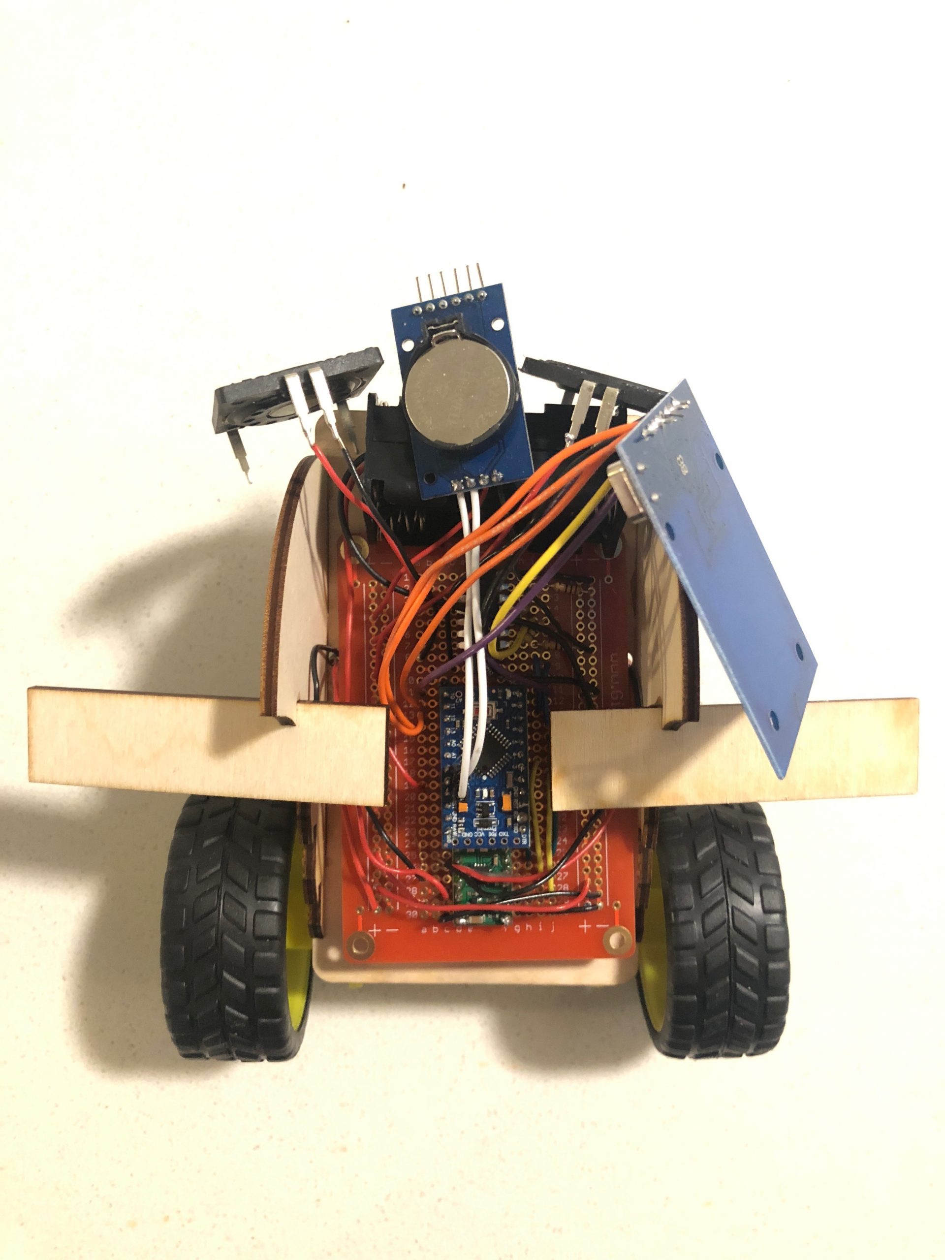
The top view of the device.
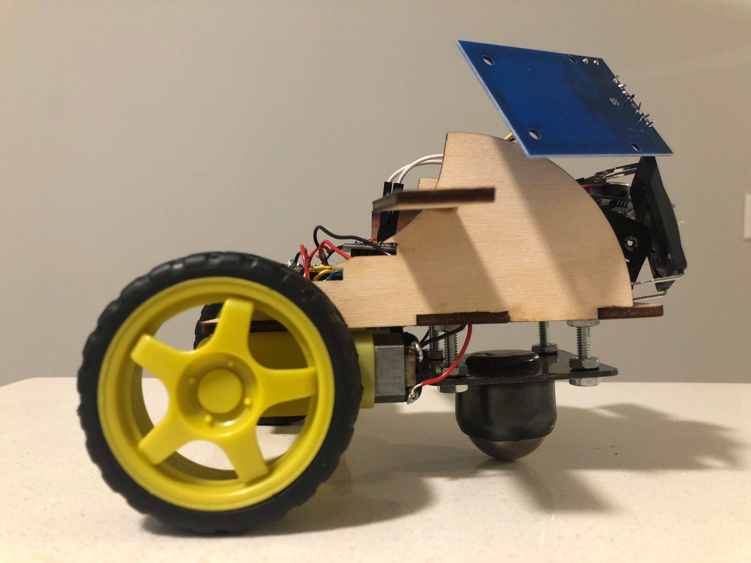
The elevation view of the device. The RFID reader sticks out so that it can get closer to the RFID card when it is reading.

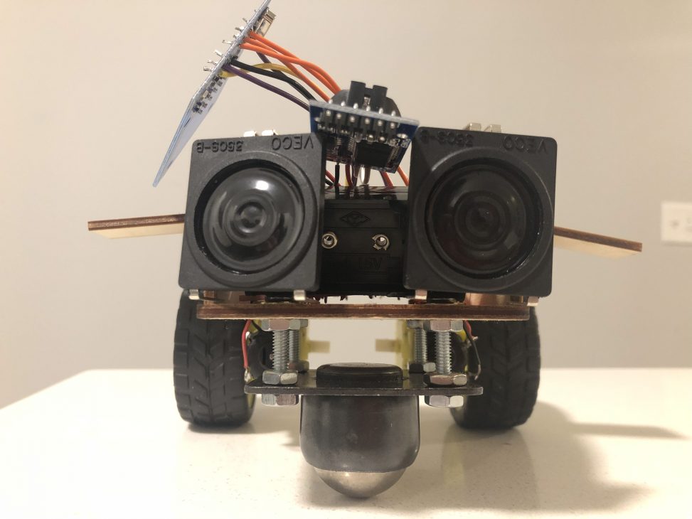
The front view of the device. The parts are arranged in a way to mimic the “face” of a robot, with the speakers being the “eyes” and the batteries case being the “nose”.
Process Image and Review
Motivation and Original Design
I have the problem of procrastinating when it comes to going to sleep. When I am busy during the week, I tend to stay up late working. When I am not as busy, I still go to bed late by watching all kinds of contends. Moreover, I tend to take shower right before I go to bed, which makes the bed time even latter. I tried to set alarm on my phone to remind myself the time for shower and sleep, but it does not work well as I usually just stop the alarm. Therefore, I wanted to build an assistive device that really grabs my attention and bring me to physical places at appropriate time.
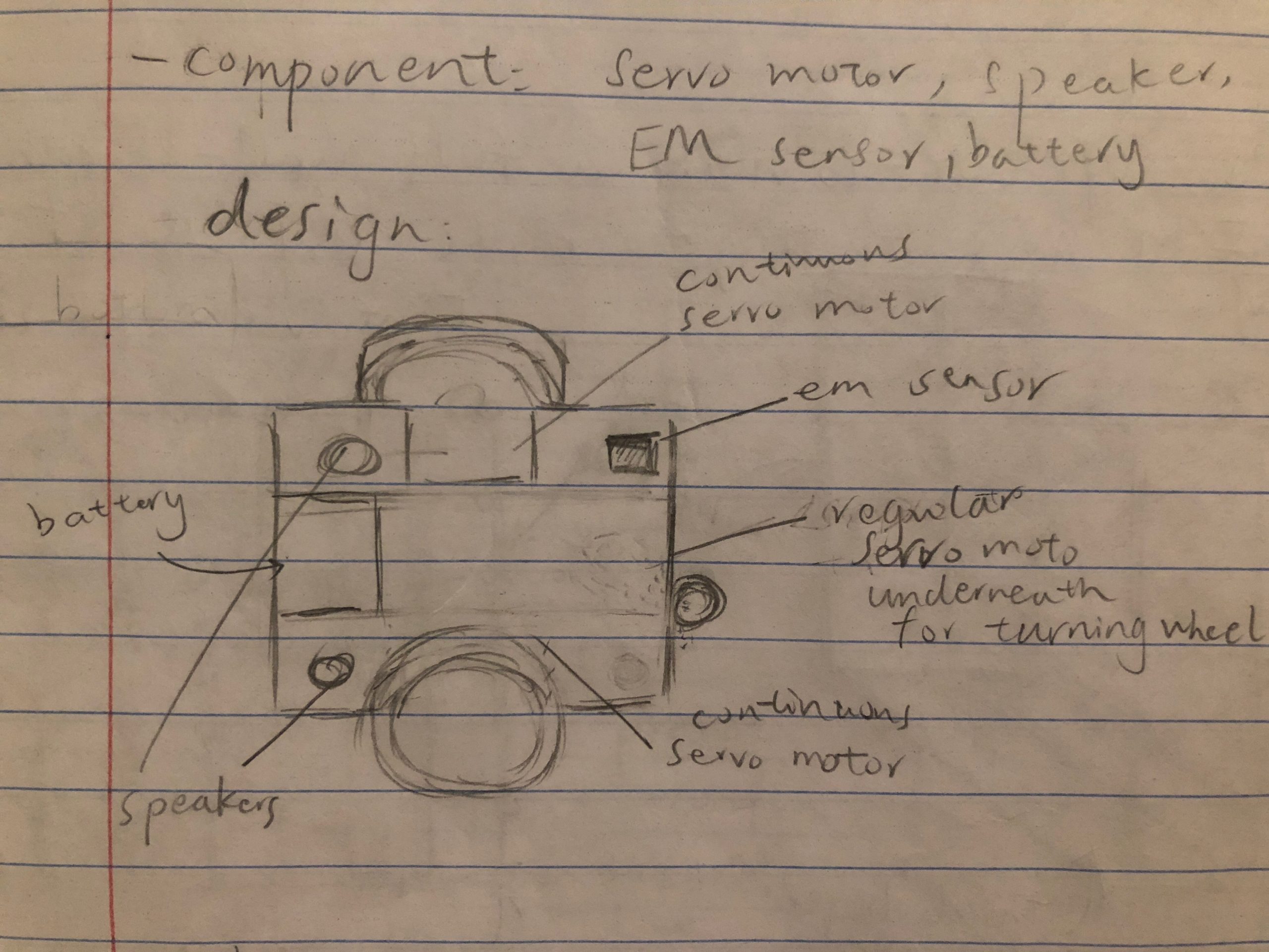
The original design from the first ideating.
The original design is a small square car that carries two speakers, an electromagnetic sensor, a servo motor, and two continuous servo motors. Magnets will be placed in bathroom and on bed, and the electromagnetic sensor is there to detect the change of EM field, which indicates the physical locations.
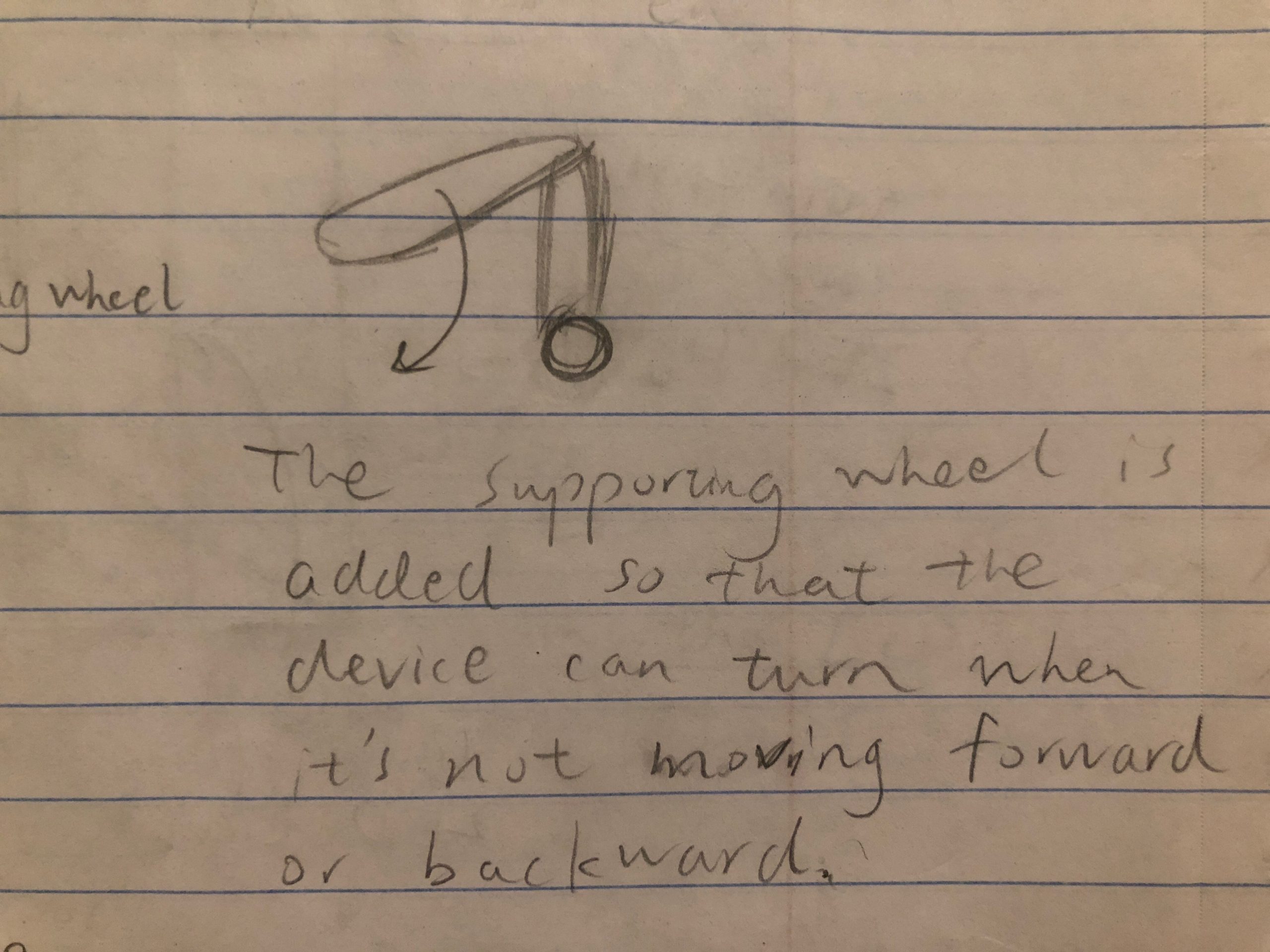
The original design of the supporting wheel.
The supporting wheel is added to maintain the balance of the body of the device as well as to help the device turn left or right driven by a servo motor. The supporting wheel is free to rotate like the wheel of a chair.
Prototyping
During prototyping, I changed the continuous servo motors to DC motors because they supply much more power. I also realized that it is very difficult to attach a wheel to the servo motor, and it is much easier to use a ball roller transfer as a supporting wheel. I was lucky enough to find a ball roller transfer that has the height similar to the radius of a toy tire, which the base of the device can sit on.
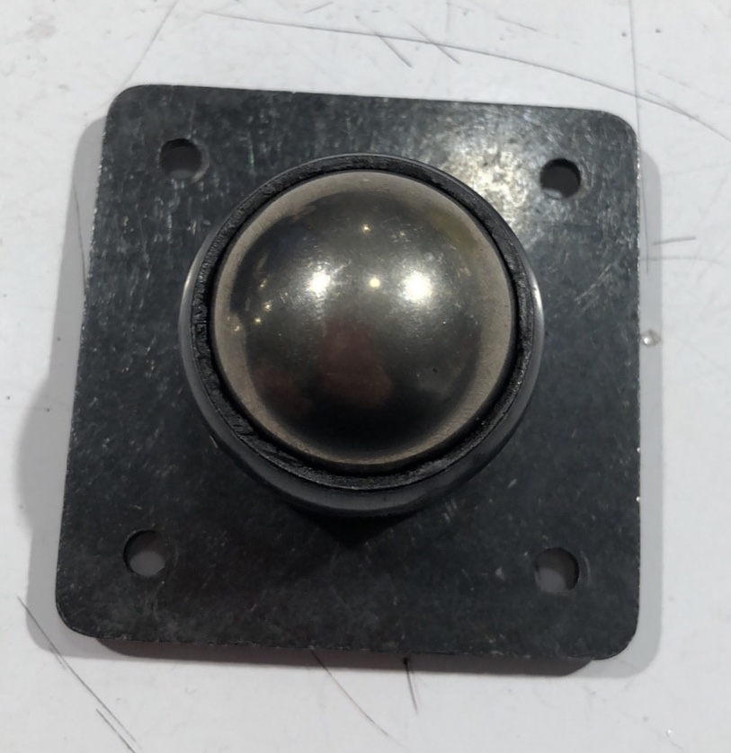
Ball roller transfer.
Then I went on to build the circuit on a breadboard. The wiring part is not bad because there are resources on the course website or online that are helpful.
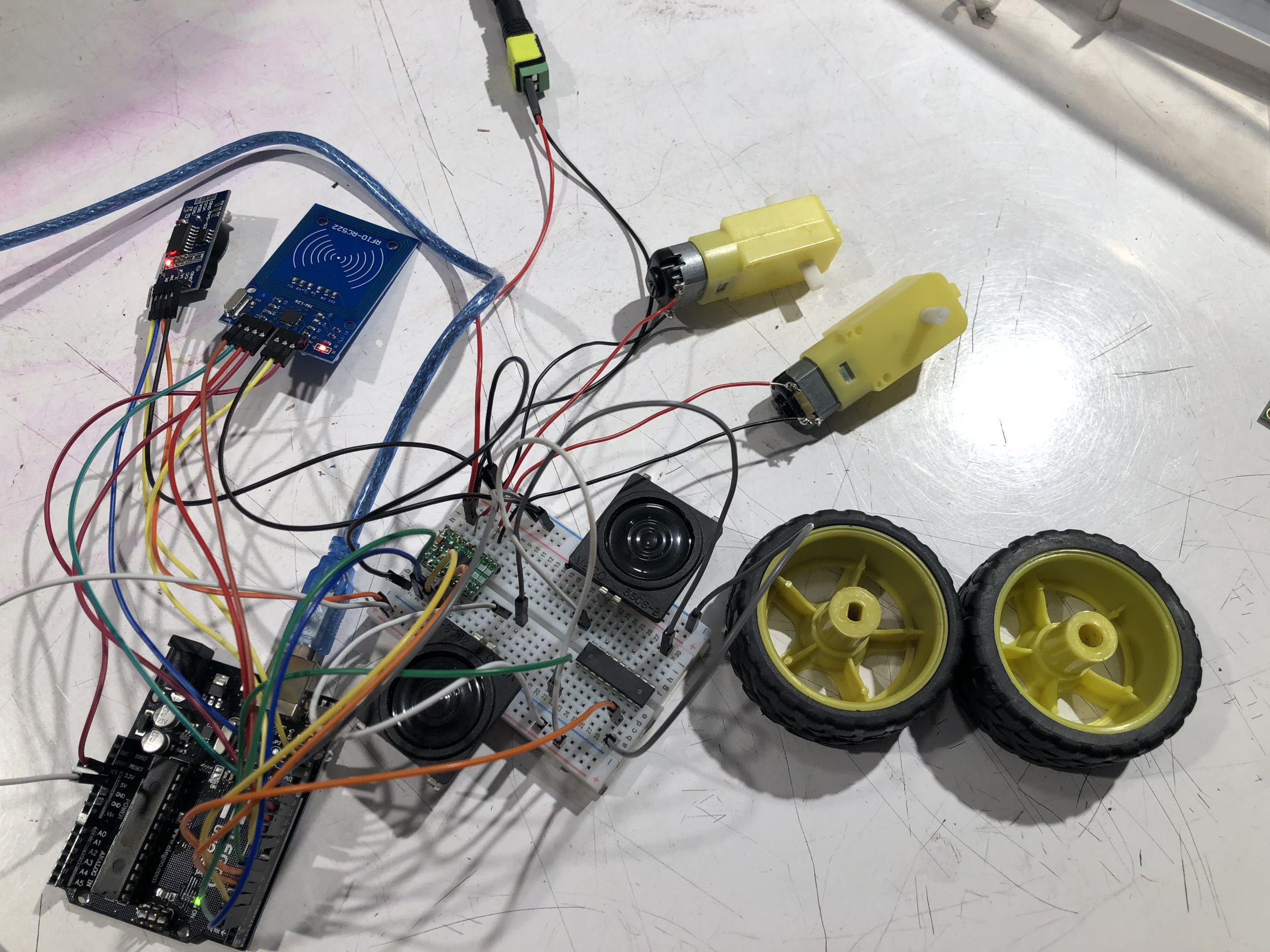
The circuit of the engineering prototype.
However, I had some trouble writing codes for parts that I was not familiar with. For example, I had to learn how to use the library for the RFID reader MFRC522 to write functions that check whether the unique “ID” of the RFID card is the one of the card in the bathroom or on the bed. However, I had the most trouble figuring out how to make the motors and speakers perform two different sequences of actions spontaneously. Then I realized I can solve it by using the blink-without-block tactic. But instead of modifying boolean variables, I have to make a “time map” and assign tasks to the parts in each time interval. However, this is not the best approach when the sequence of actions and hence the time map become long. I will introduce another approach in latter section.

In the function be_annoying, the timer diff_motor and the motor_timemap checks determine which motion to perform.
Redesigning and Building
Because the circuit of the prototype is very messy and clumpy, I decided to solder the wires and components onto a circuit board so that they can fit onto a small robot car. It turned out to be a very time-consuming process but it makes the circuit clear, strong, and secure.
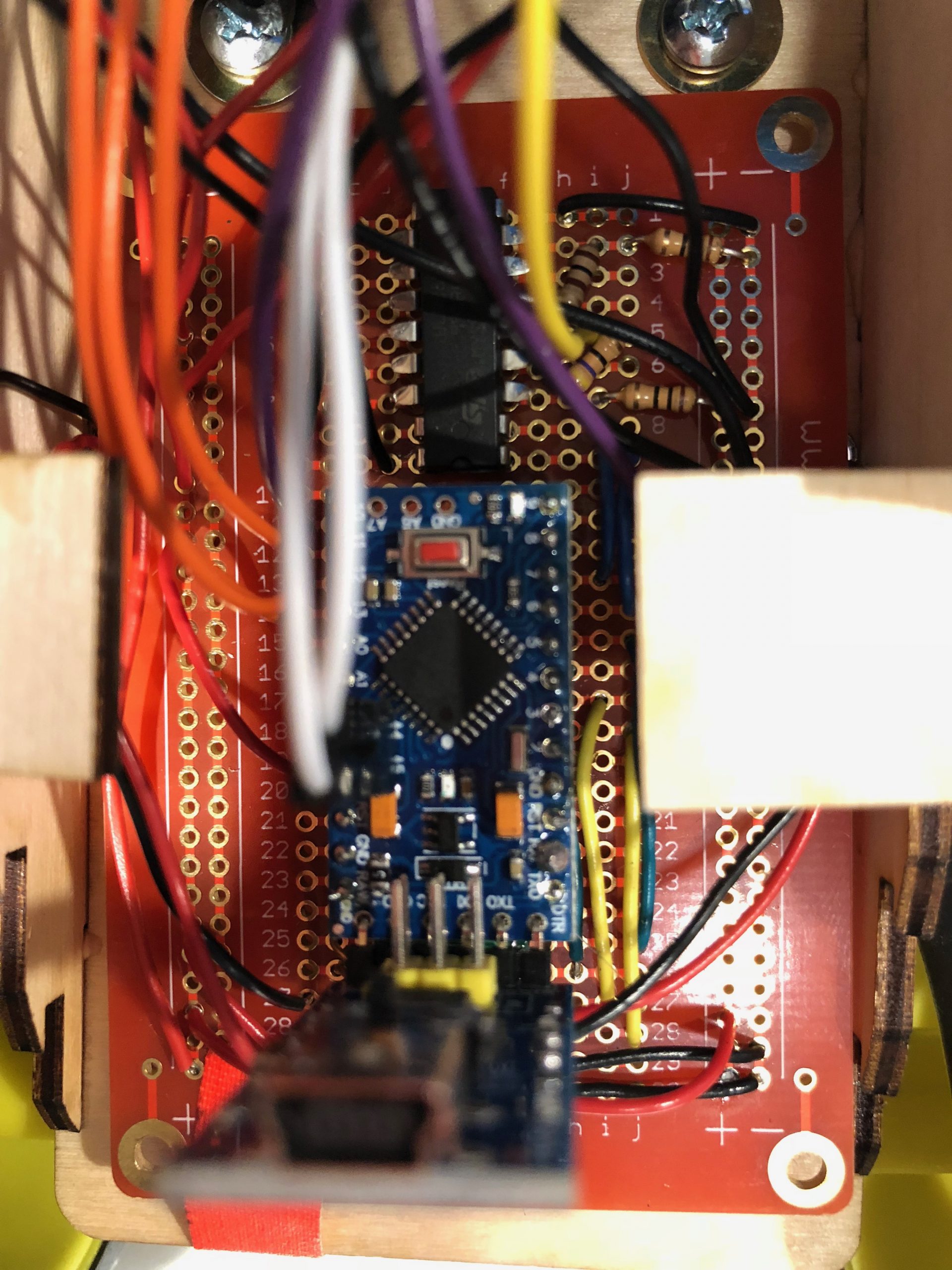
The wires and parts are all soldered onto the circuit board. To make more room from the board, I have cut the legs of the transistor on top.
I then redesign the body of the robot to fit the dimension of the circuit board and the parts. The front part of the vehicle is not covered up so that the speakers and the RFID reader to extend out for better performance. The circuit is covered by the “shields” that insert into the groves on the side boards. The idea of the “shields” are inspired by the design of the back of some Lamborghini.

Refined design of the body of the robot.

The shield above the back window. https://www.motor1.com/news/78593/after-50-years-the-lovely-lamborghini-miura-is-back/
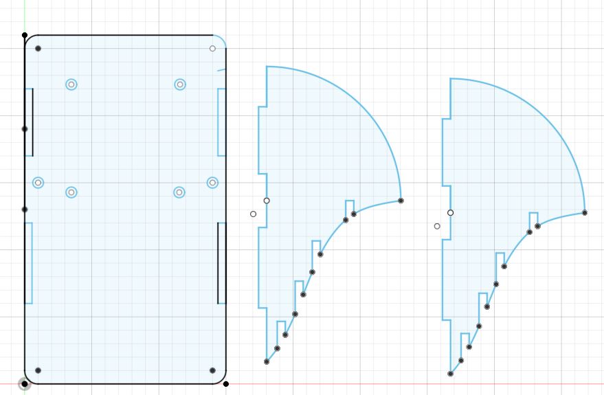
The sketch of the components. Notice that the grooves on the curved side of the right components are for the shields.
Unfortunately, the “shields” could not be used because the height of the Arduino pro mini is taller than expected due to the soldering on the circuit board. In other words, the soldering tips at the back of the circuit board raise the components up, which get into the way of the shields. Unfortunately, because I was not able to use the laser cutter again before the final critique, I had to abandon the idea and decided to make a pair of wings instead. As a result, the device has a raw look without enclosure.
Finally, the device was built by gluing the parts together and mounting the ball roller transfer onto the base with screws and nuts.
Playing a Song
Because the device was too annoying when the speakers only vibrate constantly to make loud noises, I decided to play a song instead. With two speakers, I can play two melodies at the same time.
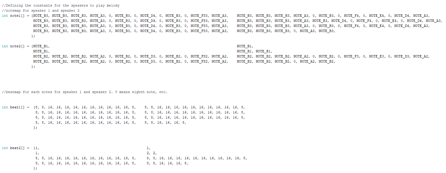
The lists of notes and the lists of beats. Each note corresponds to a specific frequency for the tone() function.
With a list of notes and a list of beats, the speaker can go through the melody using the blink-without-block technique. However, because there are substantial notes and beats, I could not use “if” anymore as it gets too tedious. As a result, a loop was written to generate the time-map by looping through the list of beat and add the previous beats up.
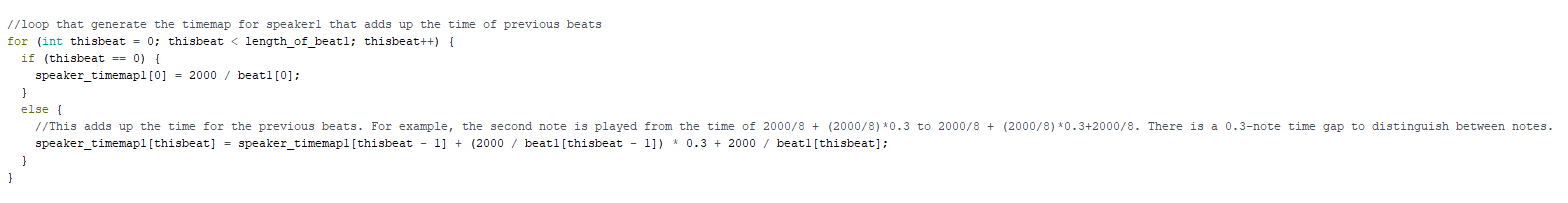
The loop that generate the time map for speaker 1.
Finally, a global variable “counter” determines which note to play and what beat it has.
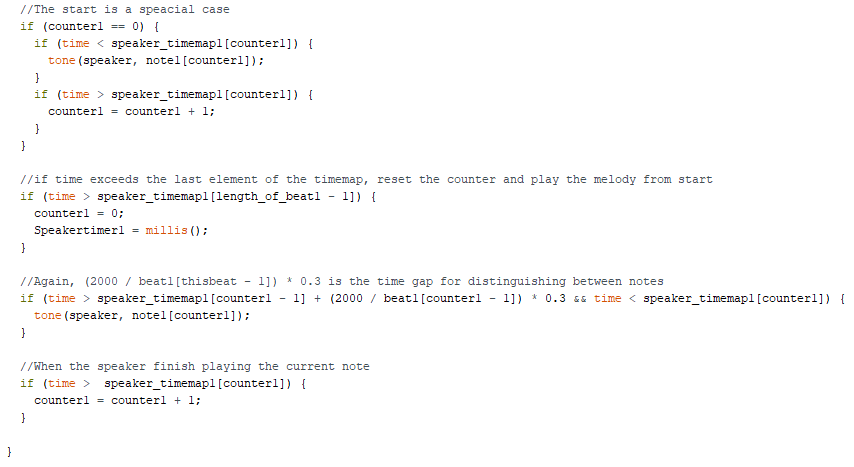
The code that tells the speaker what note to play and how long to play it.
Discussion
Feedback
One of the feedback suggested to build “a cover” to hide the device’s components while another suggested putting “a shell” and bunch of screws” around the battery . I really like these feedback because I will have a less chance to hack the system when I am not aware of the circuit and the batteries are difficult to remove. Instead of removing the batteries, now the only option to make the machine stop is to to the designated physical place to get the RFID card. As a result, the device can better serve the original purpose of making me take shower or go to sleep.
There are also feedback about “adding a flash light” and adding an interface for “adjustable time for the alarm”. With a flashlight, the robot car can grab more attention, especially at night. And with an interface to adjust the time, the device can be more user-friendly and convenient to use. Therefore, I think those are great feedback and potential improvement to the device.
Self Critique and What I have learnt
I am pleased about the function that the device can perform. All the parts, including the RFID reader and the motors, work better than I expected. As a result, the device can perfectly perform its intended job. However, I am not satisfied about the design of the final product. As mentioned before, the robot looks rather raw without cover and the wires of the parts still look kind of messy.
One of the biggest lesson I learnt is that I have to make a clear schedule before starting the project. In this project, I only have a rough schedule my mind and as I spent more and more time on the technical issues, I had to push back the task of designing until the very end. And it is a very bad idea to push anything to the very end. Instead, I should have a schedule that assigns equal time to technical and designing tasks. Moreover, if there is a technical problem that is very time consuming, I should stick to the schedule and move on. If I have more time, I can come back to the problem and finish the feature. I also learnt that it is challenging to write code for arduino if I am not familiar with the language of C. But it is also not too bad because there are many references that I can rely on.
Next Step
If I was to build another iteration, I would design a cover for the robot that the speakers and RFID reader are fixed at the surface. I would use a USB power bank instead of batteries to power the robot so that enough current would be supplied. I would use the design of the “shield” to cover up the components. I would add a LCD and a rotating switch to make an user interface for adjusting time, changing the color of the flashlight, and changing songs.
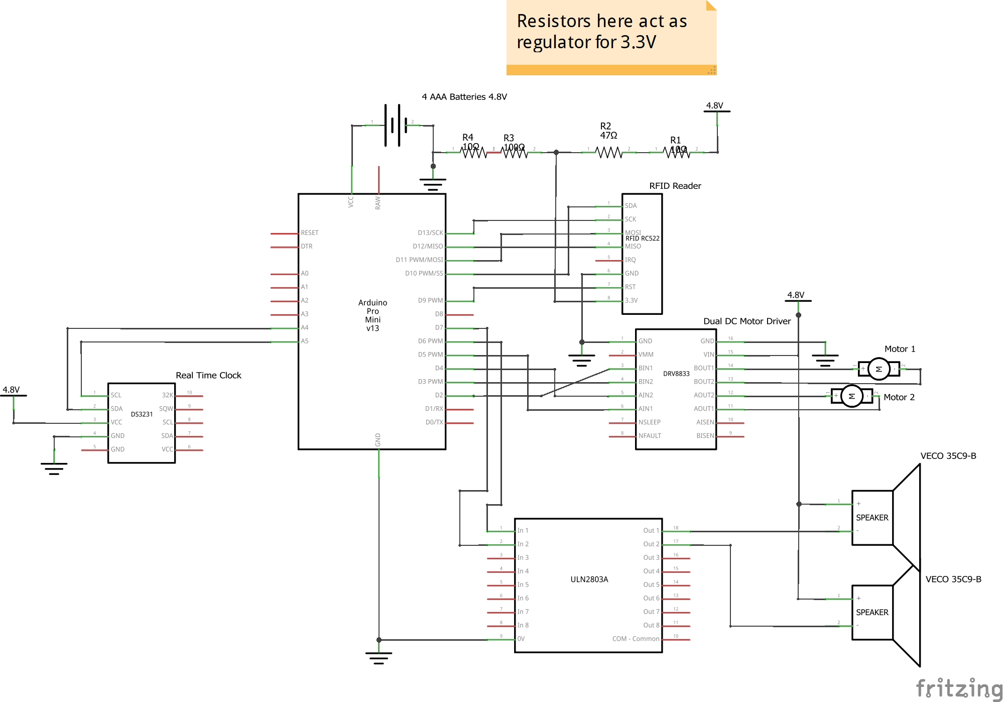
Technical information
Schematic
Code
/*Sleep Time Reminder
 * Zerui Huo
 * The code makes two motors spin and two speaker vibrate at a preset time until the RFID reader
   detects the desired RFID card.

 *Pin mapping:

     pin   | mode   | description
     ------|--------|------------
     2      OUTPUT    The pin that sends pwm signal to the motor driver and controls tire 1
     3      OUTPUT    The pin that sends pwm signal to the motor driver and controls tire 1
     4      OUTPUT    The pin that sends pwm signal to the motor driver and controls tire 2
     5      OUTPUT    The pin that sends pwm signal to the motor driver and controls tire 2
     6      OUTPUT    The pin that is connect to transistor to control speaker 1
     7      OUTPUT    The pin that is connect to transistor to control speaker 2
     9                SDA pin for the RFID reader
     10               RST pin for the RFID reader
     11               MOSI pin for the RFID reader
     12               MISO pin for the RFID reader
     13               SCK pin for the RFID reader
     A4               SDA pin for the real time clock
     A5               SCL pin for the real time clock
     VCC              The pin for power to go into the Arduino pro mini


  *The code in the functions set_motor_pwm and set_two_motors_pwm are inspired by the website https://courses.ideate.cmu.edu/16-223/f2016/text/ex/Arduino/DRV8833-motor-driver/DRV8833-motor-driver.html.
   The function getID is from the website https://lastminuteengineers.com/how-rfid-works-rc522-arduino-tutorial/.
   When writing the code to set the time in the real time clock, I refer to https://create.arduino.cc/projecthub/MisterBotBreak/how-to-use-a-real-time-clock-module-ds3231-bc90fe.
   The music score of the song, Il Vento D'Oro (Golden Wind), is from https://musescore.com/winthos/scores/5366398 by Winthos.
   The the pitch values are from https://www.arduino.cc/en/Tutorial/ToneMelody?from=Tutorial.Tone and are written by Brett Hagma.
*/

#include "pitches.h"
#include "SPI.h"
#include "MFRC522.h"
#include <Wire.h>
#include <ds3231.h>

//Naming all the pins to their function
const int motorA1 = 2;
const int motorA2 = 3;
const int motorB1 = 4;
const int motorB2 = 5;
const int speaker1 = 6;
const int speaker2 = 7;

//Define the two pins for the RFID
#define pinSDA 10
#define pinRST 9

//Setting the intervals for the all the timers
unsigned long Motortimer = 0;
unsigned long Speakertimer1 = 0;
unsigned long Speakertimer2 = 0;
unsigned long Clocktimer = 0;
const int Clockwait = 5000;

//Setting up the strings to check for the RFID reader
byte readCard[4];
String Bathroom_ID = "A06EC9B";  //Unique ID for the RFID card that will be placed in bathroom
String Bed_ID = "31BD82FC";  //Unique ID for the RFID card that will be placed onto the bed
String tagID = "";

//"Link" the pins to the RFID's SDA and RST
MFRC522 mfrc522(pinSDA, pinRST);

//For the realtime clock
struct ts t;

//Defining the constants for the speakers to play melody
//notemap for speaker 1 and speaker 2
int note1[] = {NOTE_B3, NOTE_B3, NOTE_B3, NOTE_A3, 0, NOTE_B3, 0, NOTE_D4, 0, NOTE_B3, 0, NOTE_FS3, NOTE_A3,
               NOTE_B3, NOTE_B3, NOTE_B3, NOTE_A3, 0, NOTE_B3, 0, NOTE_F4, 0, NOTE_E4, 0, NOTE_D4, NOTE_A3,
               NOTE_B3, NOTE_B3, NOTE_B3, NOTE_A3, 0, NOTE_B3, 0, NOTE_D4, 0, NOTE_B3, 0, NOTE_FS3, NOTE_A3,
               NOTE_B3, NOTE_B3, NOTE_B3, NOTE_A3, NOTE_B3, NOTE_D4, 0, NOTE_F4, 0, NOTE_E4, 0, NOTE_D4, NOTE_A3,
               NOTE_B3, NOTE_B3, NOTE_B3, NOTE_A3, 0, NOTE_B3, 0, NOTE_D4, 0, NOTE_B3, 0, NOTE_FS3, NOTE_A3,
               NOTE_B3, NOTE_B3, NOTE_B3, NOTE_A3, 0, NOTE_B3, 0, NOTE_F4, 0, NOTE_E4, 0, NOTE_D4, NOTE_A3,
               NOTE_B3, NOTE_B3, NOTE_B3, NOTE_A3, 0, NOTE_B3, 0, NOTE_D4, 0, NOTE_B3, 0, NOTE_FS3, NOTE_A3,
               NOTE_B3, NOTE_B3, NOTE_B3, 0, NOTE_A3, NOTE_B3,
              };

int note2[] = {NOTE_B1,
               NOTE_B1,
               NOTE_B1,
               NOTE_B1, NOTE_B1,
               NOTE_B2, NOTE_B2, NOTE_B2, NOTE_A2, 0, NOTE_B2, 0, NOTE_D3, 0, NOTE_B2, 0, NOTE_FS2, NOTE_A2,
               NOTE_B2, NOTE_B2, NOTE_B2, NOTE_A2, 0, NOTE_B2, 0, NOTE_F3, 0, NOTE_E3, 0, NOTE_D3, NOTE_A2,
               NOTE_B2, NOTE_B2, NOTE_B2, NOTE_A2, 0, NOTE_B2, 0, NOTE_D3, 0, NOTE_B2, 0, NOTE_FS2, NOTE_A2,
               NOTE_B2, NOTE_B2, NOTE_B2, 0, NOTE_A2, NOTE_B2,
              };


//beatmap for each notes for speaker 1 and speaker 2. 8 means eighth note, etc.
int beat1[] =  {8, 8, 16, 16, 16, 16, 16, 16, 16, 16, 16, 16, 8,    8, 8, 16, 16, 16, 16, 16, 16, 16, 16, 16, 16, 8,
                8, 8, 16, 16, 16, 16, 16, 16, 16, 16, 16, 16, 8,    8, 8, 16, 16, 16, 16, 16, 16, 16, 16, 16, 16, 8,
                8, 8, 16, 16, 16, 16, 16, 16, 16, 16, 16, 16, 8,    8, 8, 16, 16, 16, 16, 16, 16, 16, 16, 16, 16, 8,
                8, 8, 16, 16, 16, 16, 16, 16, 16, 16, 16, 16, 8,    8, 8, 16, 16, 16, 8,
               };

int beat2[] =  {1,                                                   1,
                1,                                                   2, 2,
                8, 8, 16, 16, 16, 16, 16, 16, 16, 16, 16, 16, 8,     8, 8, 16, 16, 16, 16, 16, 16, 16, 16, 16, 16, 8,
                8, 8, 16, 16, 16, 16, 16, 16, 16, 16, 16, 16, 8,     8, 8, 16, 16, 16, 8,
               };


//Determining the length of the list of beat and creat empty timemaps for the speakers
const int length_of_beat1 = 155;
const int length_of_beat2 = 1;

int speaker_timemap1[length_of_beat1];
int speaker_timemap2[length_of_beat2];

//Note counter indicate which note the speakers are on. They are set to 0 because array start from 0 and in such way they are more convenient to use latter.
int counter1 = 0;
int counter2 = 0;


//The following are written supplemental functions

//RFID:
//Funtion to access the NUID and put the first 4 bytes (8 digits) into the string "tagID"
boolean getID() {
  //Verify if any card is presented
  if ( ! mfrc522.PICC_IsNewCardPresent()) {
    return false;
  }

  // Verify if the NUID has been readed
  if ( ! mfrc522.PICC_ReadCardSerial()) {
    return false;
  }
  tagID = "";
  //A loop that put the first 4 bytes of the unique ID of the card into the variable tagID
  for ( uint8_t i = 0; i < 4; i++) {
    tagID = tagID + (String(mfrc522.uid.uidByte[i], HEX));
  }
  tagID.toUpperCase();
  mfrc522.PICC_HaltA(); // Tells the RFID readert to stop reading.
  return true;
}

//Motors:
//Function to give direction and speed to one of the motor
void set_motor_pwm(int pwm, int input_1, int input_2) {
  if (pwm < 0) {
    digitalWrite(input_1, -pwm);
    analogWrite(input_2, LOW);
  }
  else {
    digitalWrite(input_1, LOW);
    analogWrite(input_2, pwm);
  }
}

//Function that gives direction and speed to both motor using the previous function
void set_two_motors_pwm(int pwmA, int pwmB) {
  set_motor_pwm(pwmA, motorA1, motorA2);
  set_motor_pwm(pwmB, motorB1, motorB2);
}

//Speakers:

//Funtion that make the speaker play the note according to its notemap and timemap
void play_note(int speaker, int time) {
  //Determine which speaker and therefore which counter to modify
  if (speaker == 6) {
    //The start is a speacial case
    if (counter1 == 0) {
      if (time < speaker_timemap1[counter1]) {
        tone(speaker, note1[counter1]);
      }
      if (time > speaker_timemap1[counter1]) {
        counter1 = counter1 + 1;
      }
    }

    //if time exceeds the last element of the timemap, reset the counter and play the melody from start
    if (time > speaker_timemap1[length_of_beat1 - 1]) {
      counter1 = 0;
      Speakertimer1 = millis();
    }

    //Again, (2000 / beat1[thisbeat - 1]) * 0.3 is the time gap for distinguishing between notes
    if (time > speaker_timemap1[counter1 - 1] + (2000 / beat1[counter1 - 1]) * 0.3 && time < speaker_timemap1[counter1]) {
      tone(speaker, note1[counter1]);
    }

    //When the speaker finish playing the current note
    if (time >  speaker_timemap1[counter1]) {
      counter1 = counter1 + 1;
    }

  }

  if (speaker == 7) {
    //The start is a speacial case
    if (counter2 == 0) {
      if (time < speaker_timemap2[counter2]) {
        tone(speaker, note2[counter2]);
        Serial.println("Speaker 2 starts");
      }
      if (time > speaker_timemap2[counter2]) {
        counter2 = counter2 + 1;
        Serial.println("Speaker 2 counter 2");
      }
    }

    //if time exceeds the last element of the timemap, reset the counter and play the melody from start
    if (time > speaker_timemap2[length_of_beat2 - 1]) {
      counter2 = 0;
      Speakertimer2 = millis();
      Serial.println("Speaker 2 end");
    }

    //Again, (2000 / beat1[thisbeat - 1]) * 0.3 is the time gap for distinguishing between notes
    if (time > speaker_timemap2[counter2 - 1] + (2000 / beat2[counter2 - 1]) * 0.3 && time < speaker_timemap2[counter2]) {
      tone(speaker, note2[counter2]);
       Serial.println("Speaker 2 next note");
    }

    //When the speaker finish playing the current note
    if (time >  speaker_timemap2[counter2]) {
      counter2 = counter2 + 1;
    }

  }
}

//Function that controls what happen when it's time to shower/sleep
void be_annoying() {


  //how long has passed since the start of the cycle
  int diff_motor = millis() - Motortimer;
  int diff_speaker1 = millis() - Speakertimer1;
  int diff_speaker2 = millis() - Speakertimer2;

  //the timemap of actions for motors
  int motor_timemap[] = {3000, 5000, 7000, 10000};


  //motors' sequence of motions
  //Motion1
  if ( diff_motor <=  motor_timemap[0] ) {
    set_two_motors_pwm(random(-225,225),random(-225,225));
  }

  //Motion2
  if ( diff_motor >= motor_timemap[0] && diff_motor <=  motor_timemap[1] ) {
    set_two_motors_pwm(100, 100);
  }

  //Motion3
  if ( diff_motor >= motor_timemap[1]  && diff_motor <= motor_timemap[2] ) {
    set_two_motors_pwm(-200, 200);
  }

   //Motion4
  if ( diff_motor >= motor_timemap[2]  && diff_motor <= motor_timemap[3] ) {
    set_two_motors_pwm(random(-225,225), random(-225,225));
  }


  if ( diff_motor >= motor_timemap[3]) {
    //Serial.println("cycle ends");
    Motortimer = millis();
  }


  //Speaker1's sequence of actions
  play_note(speaker1, diff_speaker1);
  play_note(speaker2, diff_speaker2);
}

void setup() {
  //Setting up the motors' pins
  pinMode(motorA1, OUTPUT);
  pinMode(motorA2, OUTPUT);
  pinMode(motorB1, OUTPUT);
  pinMode(motorB2, OUTPUT);

  //Starting in the coasting mode
  digitalWrite(motorA1, LOW);
  digitalWrite(motorA2, LOW);
  digitalWrite(motorB1, LOW);
  digitalWrite(motorB2, LOW);

  //Setting up the pins for the transistor for the speakers
  pinMode(speaker1, OUTPUT);
  pinMode(speaker2, OUTPUT);

  //Initializing the RFDI
  SPI.begin();
  mfrc522.PCD_Init();

  //Initializing the serial monitor
  Serial.begin(9600);

  //Setting up for the real-time clock
  Wire.begin();
  DS3231_init(DS3231_INTCN);

  //Set up of the t for the real-time clock
  t.hour = 24;
  t.min = 30;
  t.sec = 0;
  t.mday = 30;
  t.mon = 2;
  t.year = 2020;

  DS3231_set(t);


  //loop that generate the timemap for speaker1 that adds up the time of previous beats
  for (int thisbeat = 0; thisbeat < length_of_beat1; thisbeat++) {
    if (thisbeat == 0) {
      speaker_timemap1[0] = 2000 / beat1[0];
    }
    else {
      //This adds up the time for the previous beats. For example, the second note is played from the time of 2000/8 + (2000/8)*0.3 to 2000/8 + (2000/8)*0.3+2000/8. There is a 0.3-note time gap to distinguish between notes.
      speaker_timemap1[thisbeat] = speaker_timemap1[thisbeat - 1] + (2000 / beat1[thisbeat - 1]) * 0.3 + 2000 / beat1[thisbeat];
    }
  }

  //loop that generate the timemap for speaker2 that adds up the time of previous beats
  for (int thisbeat = 0; thisbeat < length_of_beat2; thisbeat++) {
    if (thisbeat == 0) {
      speaker_timemap2[0] = 2000 / beat2[0];
    }
    else {
      //This adds up the time for the previous beats. For example, the second note is played from the time of 2000/8 + (2000/8)*0.3 to 2000/8 + (2000/8)*0.3+2000/8. There is a 0.3-note time gap to distinguish between notes.
      speaker_timemap2[thisbeat] = speaker_timemap2[thisbeat - 1] + (2000 / beat2[thisbeat - 1]) * 0.3 + 2000 / beat2[thisbeat];
    }
  }
}


void loop() {
  //The time to take shower
  if (t.hour == 23 && t.min == 0 && t.sec == 0) {
    Motortimer = millis();
    Speakertimer1 = millis();
    Speakertimer2 = millis();
    while (! getID() && tagID != Bathroom_ID) {
      be_annoying();
    }
    noTone(speaker1);
    noTone(speaker2);
    set_two_motors_pwm(0, 0);
  }


  //The time to sleep
  if (t.hour == 24 && t.min == 30 && t.sec == 0) {
    Motortimer = millis();
    Speakertimer1 = millis();
    Speakertimer2 = millis();
    while (! getID() && tagID != Bed_ID) {
      be_annoying();
    }

    set_two_motors_pwm(0, 0);
    noTone(speaker1);
    noTone(speaker2);
  }


  //Printing the time for debugging purpose
  if ( (millis() - Clocktimer) >= Clockwait ) {

    //displaying the time on the serial monitor
    DS3231_get(&t);
    Serial.print("Date : ");
    Serial.print(t.mon);
    Serial.print("/");
    Serial.print(t.mday);
    Serial.print("/");
    Serial.print(t.year);
    Serial.print("\t Hour : ");
    Serial.print(t.hour);
    Serial.print(":");
    Serial.print(t.min);
    Serial.print(".");
    Serial.println(t.sec);

    Clocktimer = millis();
  }

}
/*************************************************
 * Constants for all the notes
 *************************************************/


#define NOTE_B0  31
#define NOTE_C1  33
#define NOTE_CS1 35
#define NOTE_D1  37
#define NOTE_DS1 39
#define NOTE_E1  41
#define NOTE_F1  44
#define NOTE_FS1 46
#define NOTE_G1  49
#define NOTE_GS1 52
#define NOTE_A1  55
#define NOTE_AS1 58
#define NOTE_B1  62
#define NOTE_C2  65
#define NOTE_CS2 69
#define NOTE_D2  73
#define NOTE_DS2 78
#define NOTE_E2  82
#define NOTE_F2  87
#define NOTE_FS2 93
#define NOTE_G2  98
#define NOTE_GS2 104
#define NOTE_A2  110
#define NOTE_AS2 117
#define NOTE_B2  123
#define NOTE_C3  131
#define NOTE_CS3 139
#define NOTE_D3  147
#define NOTE_DS3 156
#define NOTE_E3  165
#define NOTE_F3  175
#define NOTE_FS3 185
#define NOTE_G3  196
#define NOTE_GS3 208
#define NOTE_A3  220
#define NOTE_AS3 233
#define NOTE_B3  247
#define NOTE_C4  262
#define NOTE_CS4 277
#define NOTE_D4  294
#define NOTE_DS4 311
#define NOTE_E4  330
#define NOTE_F4  349
#define NOTE_FS4 370
#define NOTE_G4  392
#define NOTE_GS4 415
#define NOTE_A4  440
#define NOTE_AS4 466
#define NOTE_B4  494
#define NOTE_C5  523
#define NOTE_CS5 554
#define NOTE_D5  587
#define NOTE_DS5 622
#define NOTE_E5  659
#define NOTE_F5  698
#define NOTE_FS5 740
#define NOTE_G5  784
#define NOTE_GS5 831
#define NOTE_A5  880
#define NOTE_AS5 932
#define NOTE_B5  988
#define NOTE_C6  1047
#define NOTE_CS6 1109
#define NOTE_D6  1175
#define NOTE_DS6 1245
#define NOTE_E6  1319
#define NOTE_F6  1397
#define NOTE_FS6 1480
#define NOTE_G6  1568
#define NOTE_GS6 1661
#define NOTE_A6  1760
#define NOTE_AS6 1865
#define NOTE_B6  1976
#define NOTE_C7  2093
#define NOTE_CS7 2217
#define NOTE_D7  2349
#define NOTE_DS7 2489
#define NOTE_E7  2637
#define NOTE_F7  2794
#define NOTE_FS7 2960
#define NOTE_G7  3136
#define NOTE_GS7 3322
#define NOTE_A7  3520
#define NOTE_AS7 3729
#define NOTE_B7  3951
#define NOTE_C8  4186
#define NOTE_CS8 4435
#define NOTE_D8  4699
#define NOTE_DS8 4978
Comments are closed.