
[High quality pictures were not available, but I used all pictures I have. For the documentation, I used all pictures I have, and either reused pictures throughout the document depending on needs or recreated the model digitally.]
Overview
Smart Happy Plant Chamber is an Arduino project designed to assist growing plants by implementing automatic watering and lighting systems.
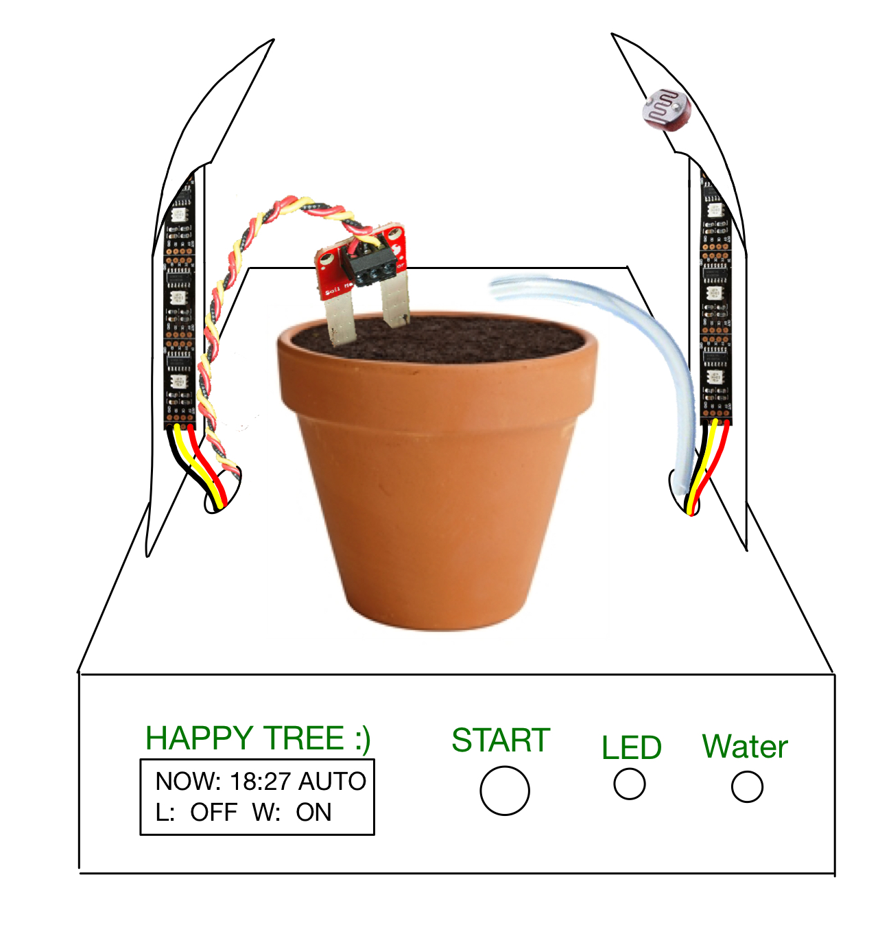
A digitally recreated picture of the completed model of chamber
The overview of a final chamber. The top has two holes each for a soil moisture sensor and motor hoses
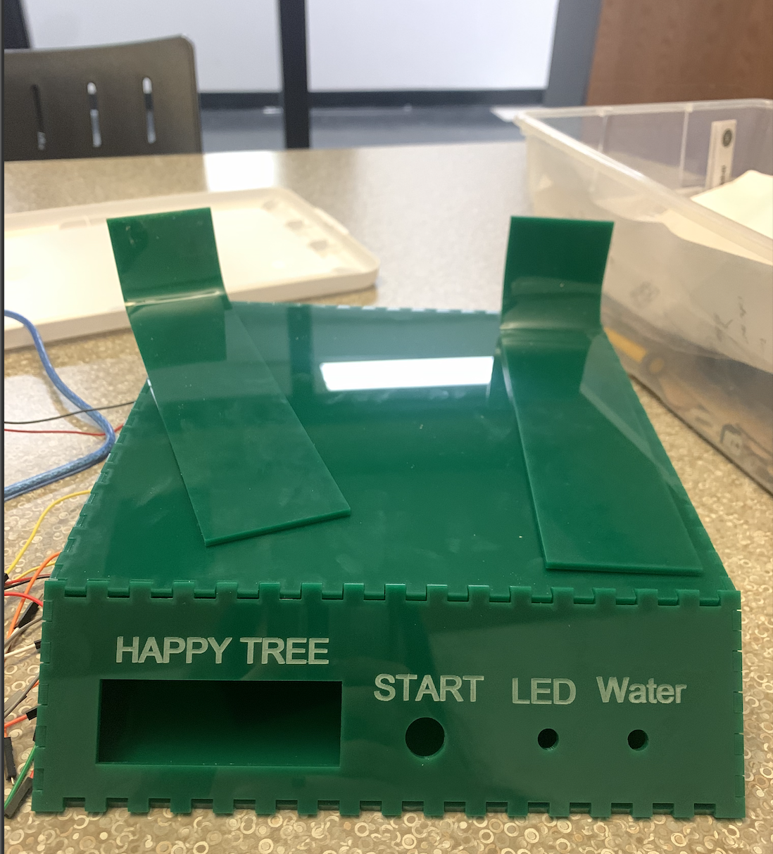
The front (Holes for an LCD screen and three switches – each labeled)
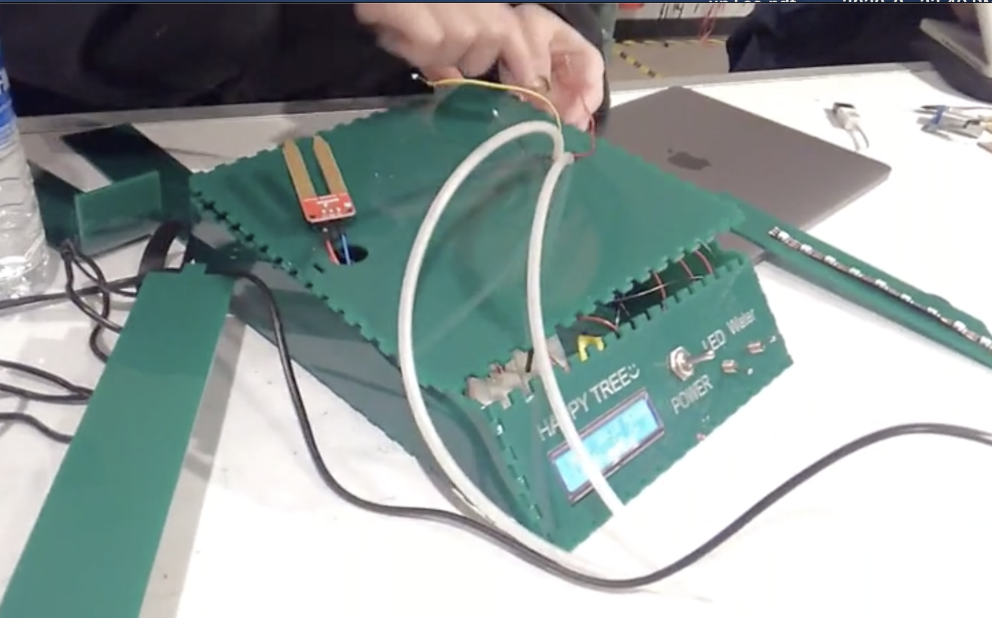
Process images and review
I had two important decision points in my project each from the software and the physical structure.
- Software
In the beginning, I was naive about designing the details of software so the machine was designed to water plants every two days and turn on the light 24 hours even without setting the default plant for the project. However, I realize not only making the physical result and making it work, but also those software choices matter in the end, so I did some research on plant growths.
I set it as house garden plants so that the user can use it for a wide range of plants. I found out, with the sensor I used a SparkFun moisture sensor, the soil moisture level should be around 50%, which is done at the household by watering the plants every 3-4 days. With these in consideration, I designed the automatic watering system to water the plant every 3 days; however, If the soil moisture level is below 50% of the water threshold point anytime during 3 days, the system will water the plant until it gets to the point, and restart the 3 days.
Moreover for the lighting, I had problems with the amount and the duration of lighting. I thought the more light the better, and white light only would be enough. However, plants also have biorhythm, so they need some time to “sleep” and to be “awake” just like us. Thus, I implemented a real-time clock into the software, so the lighting system turns on during the daytime, specifically from 7 A.M., so if the natural light is below the threshold, then the LEDs would turn on, and after 7 P.M., the lighting system turns off completely. On top of that, plants need different frequency ranges of light, from red to blue to white, which I could improve by software, fortunately. Thus, I changed my software for WS2801 LED strip to have those RGB values alternatively for each LED unit such as RGBW RGBW RGBW. I learned that conducting a project on real life is not always about technical issues, but I need to be significantly knowledgeable about the area that I am developing the technologies, which in this case was basic biology on plant growths.
- Physical Structure
Regarding the physical structure of the project, I needed to break down the structure into the bottom and top because they serve different purposes. The bottom part mainly stores most elements such as circuits, Arduino Uno, motor. For aesthetic purposes, everything that does not need to be outside for functional reasons was stored inside the bottom. The top part is where users put the actual plant. Thus it needed a flat floor for the plant, and also a proper structure for LEDs, a light sensor, water pipes, and soil moisture sensor.
For the bottom part, I was planning to make it as a cuboid, and have an LCD screen and switches on one side. However, I realized if those elements are on a side of the cuboid that is perpendicular to the floor, it will not be user friendly. Thus, I changed the bottom part to be a trapezoid column, so that the front side can be tilted to 45 degrees and users can easily use it.
For the top part, I planned to have a cuboid frame like the initial image below, but I realize first, it is not good for plants to spray water on its leaves, and second, it’s unnecessarily complicated to design. Therefore, I changed it as having two columns that will have LEDs inside and a light sensor on a top, and directly put water pipes and a moisture sensor in a plant vase.
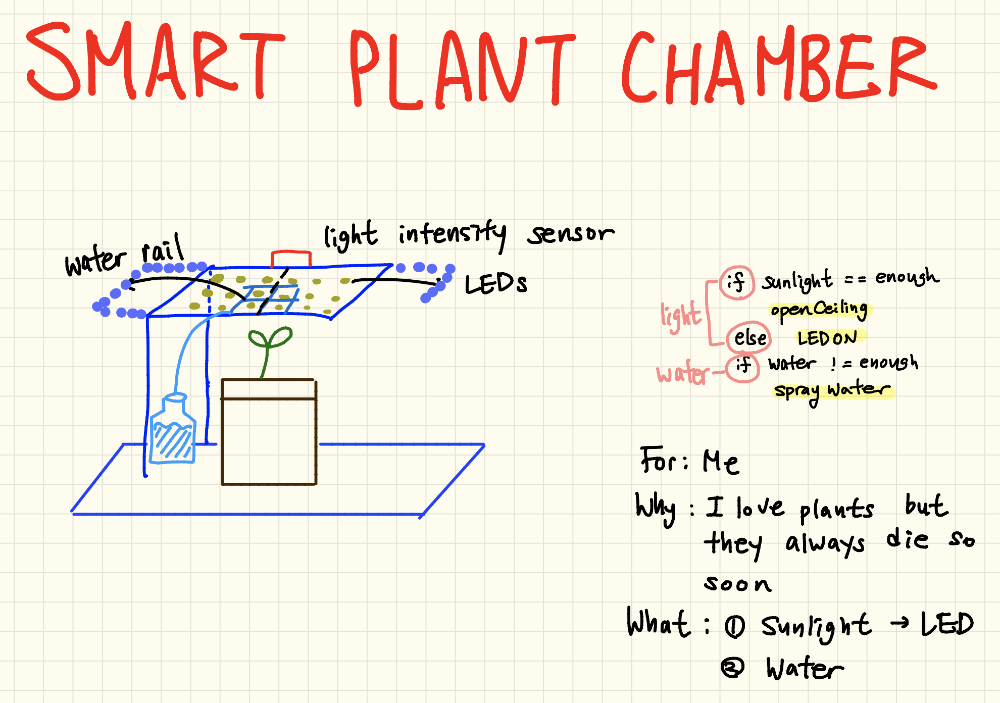
The original ideation drawing (It has a cuboid frame that carries watering and lighting systems, and does not have a bottom part that can store the rest of the model such as circuits)
The final model of chamber (The bottom is of trapezoid column with the tilted front. The top has two columns on each side for LED strips and a photoresistor)
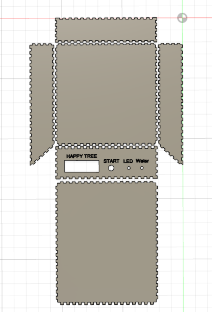
The planar figure of the bottom box (a screenshot of dxf file used for laser cutting)
Discussion
In retrospect, the most exciting part of this project was ideation in the beginning when I brainstormed which problem I would want to address. I had multiple ideas of machines that can assist my life, but in the end, I narrowed it down to a few by thinking which problems are relatable to others just as to myself. One of the project ideas that I narrowed down in this way was “Ramen Cooker”. I personally cannot cook instant ramen, so I was planning to make a ramen cooker Arduino project in the beginning. I realized this is not a common problem people have, so it might not be relatable to many other people. Some people might even ask questions like “why would you need a ‘machine’ to cook ramen?” I think this thought process helped me decide which project to work on, and I ended up making a smart chamber that grows plants automatically. I got many positive comments about the project idea, especially on how it can be useful to people who cannot grow plants well like me such as “it’s a good idea to help people who struggle with growing plants” and “the idea is very useful for people who are not good at raising plants”. I think my effort in trying to find a problem I have but also what other people can accept and relate to have worked in this kind of project where I need to perform and introduce my project to others, which is the case of most projects. Therefore, for future projects, I would want to use the same thought processes in the ideation process.
However, one significant part I missed during the planning was time management. I thought, if I make the physical outcomes of the project with appropriate design, circuits, and codes that would be the end of this project, and if I want to check it, then I can just run it. It may be true for some other types of projects; however, unlike other projects, the ultimate functionality check for this project would be growing plants at least for a week. Just as one of the comments I got, “ [I] am not sure about the functionality because we didn’t test it with a plant…”, I could not see if the plants actually grow well with the machine in the end. From this trial and error, I have learned that whenever I start any project, I need to study the environment of a project and then decide how to evaluate the results in the end, and include that into the schedule. Moreover, I had an issue with overall time management as well. Finding necessary parts and wiring them into Arduino circuits took a few days more than I expected, so I had a delay in my whole project schedule; thus, in the end, I could not finish combining everything, which I regretted the most. This was also an issue of setting a precise timeline not too tight but with the considerations of some buffers.
There were also some changes that I needed to make due to the time restraint. Originally, I did plan to have multiple modes for different types of plants because they all require different water cycles and light intensity. If I get the opportunity to repeat but improve this project in the future, I am going to plan from the start to the end in the beginning of the project including a few days to revise the semi-final outcomes and also to evaluate the result in the way I wanted to use the machine which is growing a plant with it. Moreover, I would like to add different modes for different types of plants that people often have in their houses such as herbs, succulents, etc. I am going to add a button in the front panel that users can change the mode and set the plant they have, and will add some codes according to the changes.
Technical information
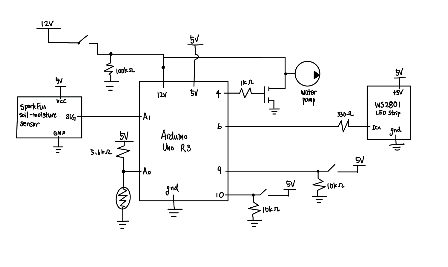
A hand-drawn schematic for the chamber
/*
 * Project2: Smart Happy Plant Chamber
 * Jeongyun Lee(jeongyul)
 *
 * Description: Following is a code for Smart Happy Plant Chamber.
 * For the lighting system, during the daytime, it turns on the LED depending on the amount of light determined by the photoresistor
 * value. During the night time, it always turns off the LED. However, when the LED manual switch is on,
 * no matter of the light value and the real time, it turns on the LED.
 * For the watering system, it evaluate whether the plant needs more water from the soil moisture sensor value,
 * and if the soil is dry, it turns on the water pump and vice versa. However, when the water manual switch is on,
 * no matter of the soil mositure value, it turns on the water pump.
 *
 * Collaboration: N/A
 * Reference: I used a part of "Adafruit Neopixel" Library "simple" example codes to initiate LED strip
 *
 * Pin mapping:
 *
 * pin    / mode    / description
 * -------/---------/------------
 * 9        input     water switch
 * 10       input     LED switch
 * A0       input     photoresistor
 * 4        output    water pump
 */

#include <Wire.h>
#include <LiquidCrystal_I2C.h>
#include "RTClib.h"
#include <Adafruit_NeoPixel.h>
#ifdef __AVR__
#include <avr/power.h>
#endif

LiquidCrystal_I2C screen(0x27, 16, 2);

const int WATERSWITCHPIN2 = 9; //water manual button
const int LIGHTSWITCHPIN3 = 10; //light manual button
const int WATERPIN = 4; //water pump pin
const int LEDPIN = 6; //led strip pin
const int MOISTUREPIN1 = A1; //moisture sensor analaog pin
const int LIGHTSENSORPIN = A0; //light sensor pin
const int NUMPIXELS = 24;

const int moistThres = 511; //below 511 = dry, above 511 = enough water
const int lightThres1 = 50; //below lightThres1: very deem
const int lightThres2 = 100; //below lightThres2: mildly deem

//current status for Automatic/Manual, for LED, and for water pump
String curStat = "AUTO";
String LEDstat = "ON ";
String WATERstat = "ON ";


RTC_DS3231 rtc;

Adafruit_NeoPixel pixels(NUMPIXELS, LEDPIN, NEO_GRB + NEO_KHZ800);

void setup() {
  pinMode(WATERSWITCHPIN2, INPUT);
  pinMode(LIGHTSWITCHPIN3, INPUT);
  pinMode(LIGHTSENSORPIN, INPUT);

  pinMode(WATERPIN, OUTPUT);
  digitalWrite(WATERPIN, LOW);

  screen.init();
  screen.backlight();
  screen.home();
  screen.print("tree happy!");
  delay(7000);
  screen.clear();

//some codes from basic real time clock library
#if defined(__AVR_ATtiny85__) && (F_CPU == 16000000)
  clock_prescale_set(clock_div_1);
#endif
#ifndef ESP8266
  while (!Serial); // for Leonardo/Micro/Zero
#endif
  pixels.begin();
  Serial.begin(9600);

//the error cases when the real time clock does not work
  if (! rtc.begin()) {
    Serial.println("Couldn't find RTC");
    while (1);
  }

  if (rtc.lostPower()) {
    Serial.println("RTC lost power, lets set the time!");
    // If the RTC have lost power it will sets the RTC to the date & time this sketch was compiled in the following line
    rtc.adjust(DateTime(F(__DATE__), F(__TIME__)));
    // This line sets the RTC with an explicit date & time, for example to set
    // January 21, 2014 at 3am you would call:
    // rtc.adjust(DateTime(2014, 1, 21, 3, 0, 0));
  }
}

//A helper function for turning on a side of LED strip
void led1() {
  pixels.setPixelColor(0, pixels.Color(0, 0, 255));
  pixels.setPixelColor(1, pixels.Color(0, 255, 0));
  pixels.setPixelColor(2, pixels.Color(255, 0, 0));
  pixels.setPixelColor(3, pixels.Color(255, 255, 255));

  pixels.setPixelColor(4, pixels.Color(0, 0, 255));
  pixels.setPixelColor(5, pixels.Color(0, 255, 0));
  pixels.setPixelColor(6, pixels.Color(255, 0, 0));
  pixels.setPixelColor(7, pixels.Color(255, 255, 255));

  pixels.setPixelColor(8, pixels.Color(0, 0, 255));
  pixels.setPixelColor(9, pixels.Color(0, 255, 0));
  pixels.setPixelColor(10, pixels.Color(255, 0, 0));
  pixels.setPixelColor(11, pixels.Color(255, 255, 255));

  pixels.show();
}

//A helper function for turning on the other side of LED strip
void led2 () {
  pixels.setPixelColor(12, pixels.Color(0, 0, 255));
  pixels.setPixelColor(13, pixels.Color(0, 255, 0));
  pixels.setPixelColor(14, pixels.Color(255, 0, 0));
  pixels.setPixelColor(15, pixels.Color(255, 255, 255));

  pixels.setPixelColor(16, pixels.Color(0, 0, 255));
  pixels.setPixelColor(17, pixels.Color(0, 255, 0));
  pixels.setPixelColor(18, pixels.Color(255, 0, 0));
  pixels.setPixelColor(19, pixels.Color(255, 255, 255));

  pixels.setPixelColor(20, pixels.Color(0, 0, 255));
  pixels.setPixelColor(21, pixels.Color(0, 255, 0));
  pixels.setPixelColor(22, pixels.Color(255, 0, 0));
  pixels.setPixelColor(23, pixels.Color(255, 255, 255));

  pixels.show();
}

//A helpter function for turning on/off the water pump
void water() {
  delay(10);
  int moistVal = analogRead(MOISTUREPIN1);
  //when there is enough mositure in soil: water pump off
  if (moistVal >= moistThres) {
      WATERstat = "OFF";
      digitalWrite(WATERPIN, LOW);
  }
  //when there isn't enough mositure in soil: water pump on
  else {
      WATERstat = "ON ";
      digitalWrite(WATERPIN, HIGH);
      delay(5000);
  }
}

//A helper function for turning on/off the LEDs
void light(int hour) {
  int lightVal = analogRead(LIGHTSENSORPIN);

  //Daytime
  if (hour >= 7 && hour <= 16) {
    if (lightVal < lightThres1) {
      //when the light is very deem
      LEDstat = "ON ";
      led1();
    }
    else if (lightVal >= lightThres1 && lightVal < lightThres2) {
      //when the light is mildly deem
      LEDstat = "ON ";
      led1();
      led2();
    }
    else {
      //when the light is enough
      LEDstat = "OFF";
      pixels.clear();
    }
  }

  //Night time
  else {
    //at night, the light is always off
    digitalWrite(LEDPIN, LOW);
    LEDstat = "OFF";
  }
}

void loop() {
  DateTime now = rtc.now();

  //manual mode buttons
  int waterState = digitalRead(WATERSWITCHPIN2); //water manual on/off
  int lightState = digitalRead(LIGHTSWITCHPIN3); //water manual on/off

  //Setting modes
  //Water: manual, LED: manual
  if (waterState == HIGH && lightState == HIGH)
  {
    curStat = "MANU";
    digitalWrite(WATERPIN, HIGH);
    digitalWrite(LEDPIN, HIGH);
    LEDstat = "ON ";
    led1();
    led2();
  }
  //Water: manual, LED: auto
  else if (waterState == HIGH && lightState == LOW)
  {
      curStat = "MANU";
      digitalWrite(WATERPIN, HIGH);
      light(now.hour());
  }
  //Water: auto, LED: manual
  else if (waterState == LOW && lightState == HIGH)
  {
    curStat = "MANU";
    water();
    digitalWrite(LEDPIN, HIGH);
    led1();
    led2();
    LEDstat = "ON ";
    //delay(500);
  }
  //Water: auto, LED: auto
  else
  {
    curStat = "AUTO";
    water();
    light(now.hour());
  }

  //LCD screen print
  screen.clear();
  screen.setCursor(1, 0);
  screen.print("Now: ");
  screen.setCursor(6, 0);
  screen.print(now.hour());
  screen.setCursor(8, 0);
  screen.print(":");
  screen.setCursor(9, 0);
  screen.print(now.minute());
  screen.setCursor(12, 0);
  screen.print(curStat);
  screen.setCursor(1, 1);
  screen.print("L: ");
  screen.setCursor(4, 1);
  screen.print(LEDstat);
  screen.setCursor(7, 1);
  screen.print("  W: ");
  screen.setCursor(12, 1);
  screen.print(WATERstat);
  Serial.print(analogRead(LIGHTSENSORPIN));
}
Comments are closed.