Note: I wanted to make the connections permanent and replace small breadboard with a pro board if I had continued access to the Physical computing lab. Additionally, I also wanted to make an enclosing that housed the various components.
Overview
This is a prototype of a wearable device that assists in navigation by providing tactile directional instructions to the user to assist them in wayfinding while navigating unfamiliar routes in a simple outdoor environment.
Motivation
A few years ago I was driving to my new workplace for the first time and I was using a maps application on my phone to guide me in my navigation. Midway, I was confused about which turn to take and I glanced over at my phone as I was trying to figure out what turn to take while I was driving. It was then that I was pulled over by the traffic police for using my phone while driving. That’s when I thought to myself, how am I supposed to use a navigation system, that mainly relies on visual directional instructions when I’m driving if I’m supposed to keep my eyes on the road at all times?
Final Images
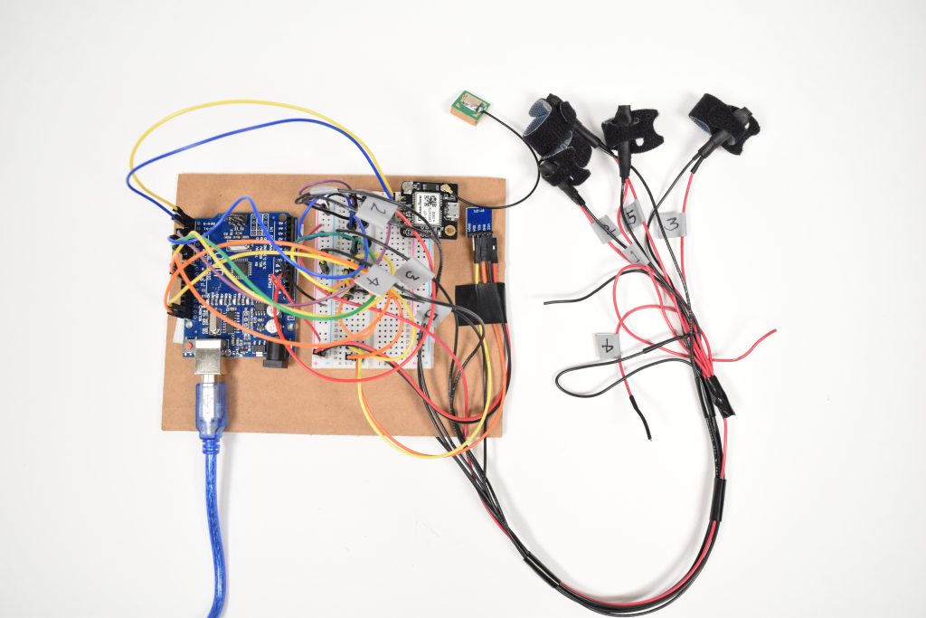
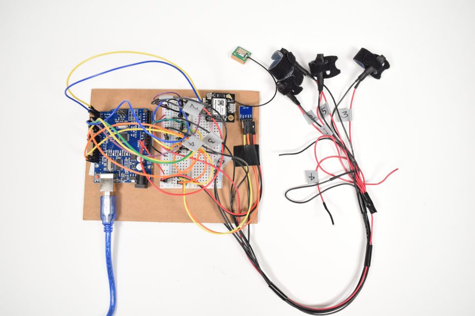
An overview of the tactile wearable showing the various parts.
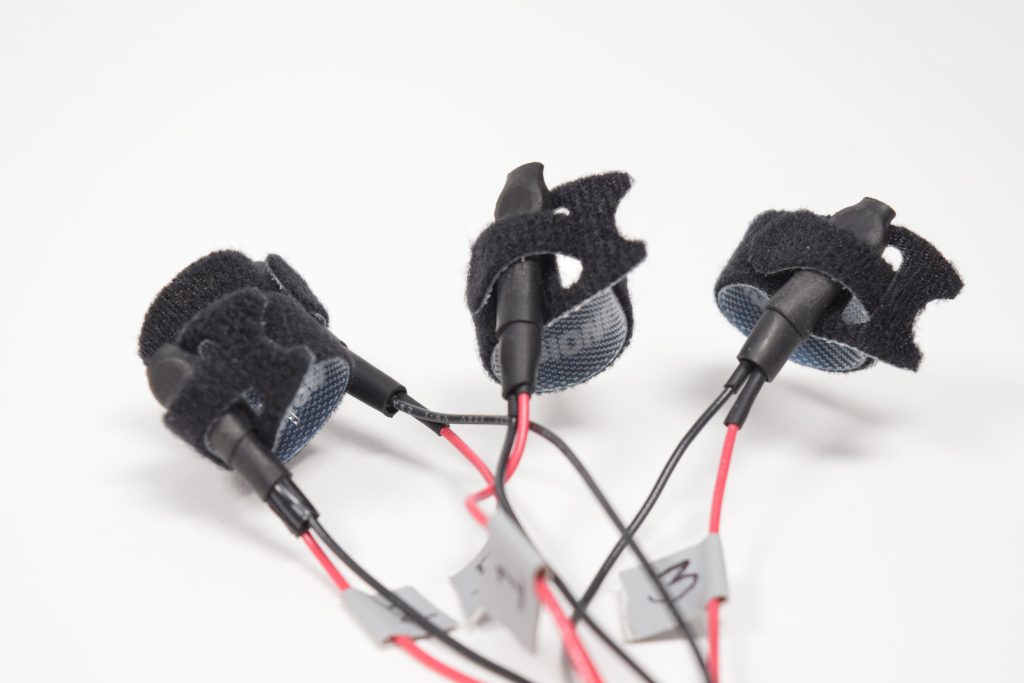
Coin vibration motors mounted velcro adjustable rings that go around the fingers.
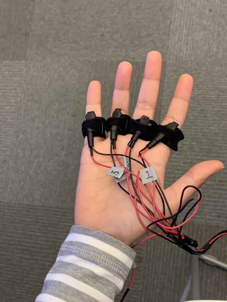
The tactile wearable mounted on the dominant hand of the user.
Final video
Note: Since I was unable to record the final video myself, I used the video that Harshine shot during my demo in class. (Thanks Harshine!)
Process images and review
I initially created a storyboard to draw out scenarios of use for the tactile wearable. The storyboard helped me figure out an appropriate form factor for the device as well.
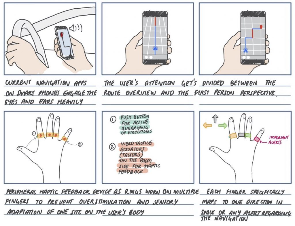
Initial storyboard illustrating the use case for the device.
Throughout the process of building this device, I got to learn how to use many sensors and components that I had never used before so it was a great opportunity for me to expand my skills in physical computing.
One such component was the GPS module. Oh the GPS module… Since this was a fairly complex component to use, I had to use a pre-written code to read the signal from the GPS module. The GPS module that I was using was a Geekstory GT-U7 GPS Module GPS that had a GPS chip and an external antenna. The GPS also had a position fix LED indicator light that indicated that the GPS was searching for satellites when it was not blinking and that the GPS had fixed on a satellite by blinking every second. I downloaded the pre-written code and connected up the GPS module and the Arduino. And then there were a few problems I ran into.
The GPS was not finding a position fix
I was excited when I first connected up all the components and expected it to work right away. However, the GPS was not fixing on a satellite although I had left it connected for several minutes. I then realized that it was almost impossible to get a GPS reading sitting in the Phys Comp lab (no surprises there). So, I went outside and stood under the clear sky for several minutes, walked around even, and then the little LED started blinking!

Getting the GPS to find a position fix by taking it outside under clear skies.
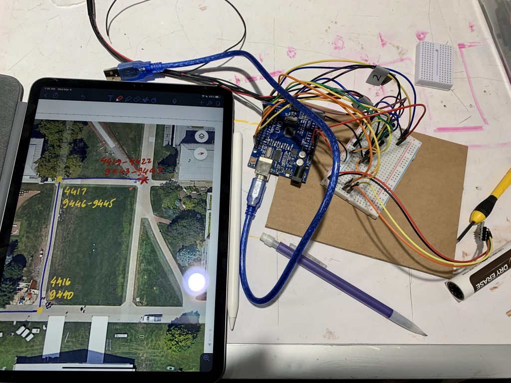
Marking the GPS coordinates on a simple outdoor to create a working demo.
And then there was a delay!
After I got the GPS to find a position fix, the GPS started transmitting signals that were a bunch of latitude and longitude coordinates. However, when I would move around, the GPS wasn’t able to update the coordinates. There seemed to be a lag in the updating of the location. I tried many things to fix this, I rechecked if all the connections were good, I ensured that I was away from buildings, I restarted my Arduino, I even held up the antenna of the GPS over my head. I even checked to make sure that I had uploaded the pre-written code exactly as it was, line by line and that was the problem! I consulted with Zac about this and upon reading the code line by line, he found a pesky little delay of 1 second right at the end of the code. The delay was originally meant to set the rate at which the GPS prints the latitude and longitude coordinates however, it was also messing up the signal that the GPS was transmitting. The GPS was picking up signals from satellites at a faster rate than it was able to transmit them which caused the signals to get jumbled up. We fixed this problem by using millis instead. Lesson learned: millis for life.
The pesky delay at the end that was the root of all problems!
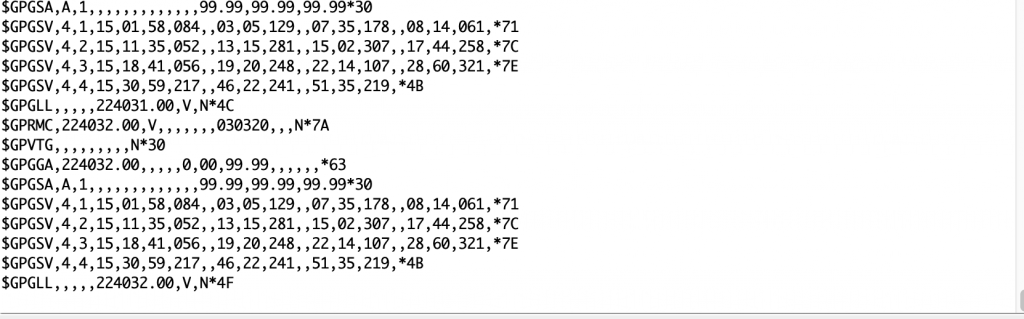
Reading raw data from the GPS.
The super-sensitive vibration motors
To create vibrotactile feedback in the wearable, I was using a small coin vibrational motor that had two very thin and fragile connecting leads onto which longer connecting wires had to be soldered. However, since the connection was so delicate, I was afraid of breaking the connections which made testing the prototype a huge challenge. I consulted with Zac and asked him how I could make the prototype more robust. Zac was extremely helpful and suggested I used heat shrinking material to reinforce the joints with the connections. He drew a wonderful diagram to illustrate the process which was helped me reinforce the connections and make the prototype durable.
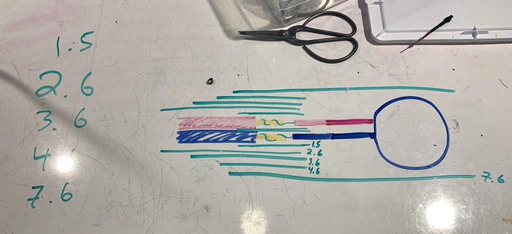
A diagram illustrating the process of reinforcing the vibration motor with different diameters of heat shrink tubing, courtesy Zac.
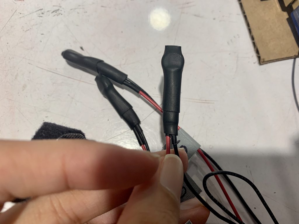
The final outcome of the reinforcing the vibration motor that made the prototype suitable to test multiple times without the fear of the connections breaking.
Discussion
To present our projects, we had an in-class demo that went differently than I imagined. I had prepared to demo the device outdoors since that was the best way I could demo the device and show that it actually worked in the way I had described it would. The demo, however, was only conducted indoors which meant I had to hard code the coordinates and fake the feedback from the wearable, which I was able to successfully do. One comment I got was the “the demo could have involved a visual aspect to show what was going on in the device (to the audience)”. I agree that LED lights would have probably helped to better indicate which vibrational motors were active. Since I was prepared for a live demo, in which a volunteer would be guided from a preset origin to a destination along a simple route outdoors, I was unable to add a visual component to the demo. I intended to add LED lights to the vibrational rings for demo purposes post-spring break which I, unfortunately, couldn’t do.
Another comment I received was “It would’ve been nice to have an enclosing for the device.” I agree with this feedback, however, the challenge was that the connections hadn’t been reinforced yet so I was afraid to make anything permanent since I only had a limited number of small coin vibrational motors available. Another challenge was that the GPS unit had to have a view of the clear sky, so enclosing it in a bix might have interfered with its ability to find a position fix.
Overall, I learned so much through this project. Not only did I gain technical skills but this project also made me persevere and build the thing I intended to build no matter the technical difficulties I ran into. Zac was instrumental in encouraging me along the way and creating a project that I was in the end proud of. There were times in the project when I wanted to give up and switch to a simpler technique, but Zac’s timely help pushed me towards the finish line.
I truly enjoyed figuring out the code for this project since it involved a fair bit of complex logic. I had taken a Python course in one of the previous semesters and my knowledge of coding came in very handy for this project. The next time I will be more vigilant when I use pre-written code because it may not always be correct. I was also surprised that I found soldering extremely therapeutic. From this project, I was able to learn how to make well-soldered connections.
If I have access to resources, I would want to work on the form and the ergonomics of the prototype. I would create a well-designed enclosing to house all the components, I would create more aesthetically pleasing rings that can easily be mounted on the hand of the user. I would also want to test out the prototype with participants in the context of outdoor navigation and evaluate the prototype.
Technical information
Schematic
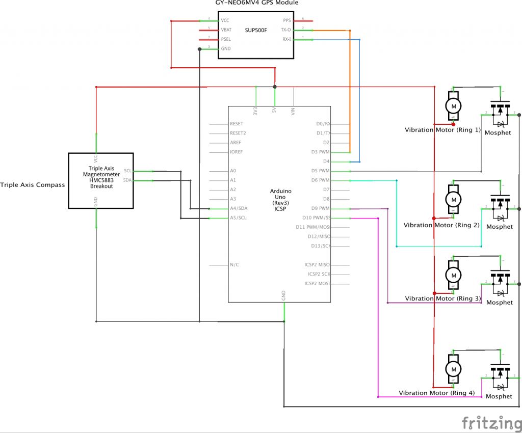
Schematic for the tactile navigation wearable
Code
- <span class="com">/*
- Project 2: Tactile Navigation Wearable
- By Aadya Krishnaprasad
- Description: This is the code for a prototype of a wearable device that assists in navigation by providing tactile directional instructions to the user to assist them in wayfinding while navigating unfamiliar routes in a simple outdoor environment.
- Pin Mapping:
- pin | mode | description
- ---------|-----------|-------------
- 3 Output GPS module tx
- 4 Input GPS module rx
- 5 Output Vibration motor (RING1)
- 6 Output Vibration motor (RING2)
- 9 Output Vibration motor (RING3)
- 10 Output Vibration motor (RING4)
- */</span><span class="pln">
- </span><span class="com">// Compass SETUP</span><span class="pln">
- </span><span class="com">#include</span><span class="pln"> </span><span class="str"><QMC5883LCompass.h></span><span class="pln">
- QMC5883LCompass compass</span><span class="pun">;</span><span class="pln">
- </span><span class="com">//Citation: GPS code from: https://create.arduino.cc/projecthub/ruchir1674/how-to-interface-gps-module-neo-6m-with-arduino-8f90ad</span><span class="pln">
- </span><span class="com">// GPS SETUP</span><span class="pln">
- </span><span class="com">#include</span><span class="pln"> </span><span class="str"><SoftwareSerial.h></span><span class="pln">
- </span><span class="com">#include</span><span class="pln"> </span><span class="str"><TinyGPS.h></span><span class="pln">
- </span><span class="com">//long lat,lon; // create variable for latitude and longitude object</span><span class="pln">
- </span><span class="kwd">float</span><span class="pln"> lat </span><span class="pun">=</span><span class="pln"> </span><span class="lit">28.5458</span><span class="pun">,</span><span class="pln"> lon </span><span class="pun">=</span><span class="pln"> </span><span class="lit">77.1703</span><span class="pun">;</span><span class="pln"> </span><span class="com">// create variable for latitude and longitude object</span><span class="pln">
- </span><span class="com">//float lat = 40.4412, lon = -79.9435; // Location: Origin, Head West</span><span class="pln">
- </span><span class="com">//float lat = 40.4414, lon = -79.9440; // Location: Waypoint 1, Head North</span><span class="pln">
- </span><span class="typ">SoftwareSerial</span><span class="pln"> gpsSerial</span><span class="pun">(</span><span class="lit">3</span><span class="pun">,</span><span class="pln"> </span><span class="lit">4</span><span class="pun">);</span><span class="pln"> </span><span class="com">//tx,rx</span><span class="pln">
- </span><span class="typ">TinyGPS</span><span class="pln"> gps</span><span class="pun">;</span><span class="pln"> </span><span class="com">// create gps object</span><span class="pln">
- </span><span class="com">// RING PIN ASSIGNMENT</span><span class="pln">
- </span><span class="kwd">const</span><span class="pln"> </span><span class="kwd">int</span><span class="pln"> RING1 </span><span class="pun">=</span><span class="pln"> </span><span class="lit">5</span><span class="pun">;</span><span class="pln">
- </span><span class="kwd">const</span><span class="pln"> </span><span class="kwd">int</span><span class="pln"> RING2 </span><span class="pun">=</span><span class="pln"> </span><span class="lit">6</span><span class="pun">;</span><span class="pln">
- </span><span class="kwd">const</span><span class="pln"> </span><span class="kwd">int</span><span class="pln"> RING3 </span><span class="pun">=</span><span class="pln"> </span><span class="lit">7</span><span class="pun">;</span><span class="pln">
- </span><span class="kwd">const</span><span class="pln"> </span><span class="kwd">int</span><span class="pln"> RING4 </span><span class="pun">=</span><span class="pln"> </span><span class="lit">9</span><span class="pun">;</span><span class="pln">
- </span><span class="kwd">void</span><span class="pln"> setup</span><span class="pun">()</span><span class="pln"> </span><span class="pun">{</span><span class="pln">
- </span><span class="typ">Serial</span><span class="pun">.</span><span class="kwd">begin</span><span class="pun">(</span><span class="lit">9600</span><span class="pun">);</span><span class="pln">
- compass</span><span class="pun">.</span><span class="pln">init</span><span class="pun">();</span><span class="pln">
- gpsSerial</span><span class="pun">.</span><span class="kwd">begin</span><span class="pun">(</span><span class="lit">9600</span><span class="pun">);</span><span class="pln"> </span><span class="com">// connect gps sensor</span><span class="pln">
- pinMode</span><span class="pun">(</span><span class="pln">RING1</span><span class="pun">,</span><span class="pln"> OUTPUT</span><span class="pun">);</span><span class="pln">
- pinMode</span><span class="pun">(</span><span class="pln">RING2</span><span class="pun">,</span><span class="pln"> OUTPUT</span><span class="pun">);</span><span class="pln">
- pinMode</span><span class="pun">(</span><span class="pln">RING3</span><span class="pun">,</span><span class="pln"> OUTPUT</span><span class="pun">);</span><span class="pln">
- pinMode</span><span class="pun">(</span><span class="pln">RING4</span><span class="pun">,</span><span class="pln"> OUTPUT</span><span class="pun">);</span><span class="pln">
- </span><span class="pun">}</span><span class="pln">
- </span><span class="kwd">void</span><span class="pln"> loop</span><span class="pun">()</span><span class="pln"> </span><span class="pun">{</span><span class="pln">
- </span><span class="kwd">int</span><span class="pln"> a</span><span class="pun">;</span><span class="pln">
- </span><span class="kwd">int</span><span class="pln"> WAIT </span><span class="pun">=</span><span class="pln"> </span><span class="lit">250</span><span class="pun">;</span><span class="pln">
- </span><span class="kwd">long</span><span class="pln"> timer </span><span class="pun">=</span><span class="pln"> </span><span class="lit">0</span><span class="pun">;</span><span class="pln">
- </span><span class="kwd">if</span><span class="pln"> </span><span class="pun">(</span><span class="pln"> </span><span class="pun">(</span><span class="pln">millis</span><span class="pun">()</span><span class="pln"> </span><span class="pun">-</span><span class="pln"> timer</span><span class="pun">)</span><span class="pln"> </span><span class="pun">>=</span><span class="pln"> WAIT </span><span class="pun">)</span><span class="pln"> </span><span class="pun">{</span><span class="pln"> </span><span class="com">// millis() is always the number of milliseconds since the Arduino powered up</span><span class="pln">
- </span><span class="com">// Read compass values ; Compass 0 is East</span><span class="pln">
- compass</span><span class="pun">.</span><span class="pln">read</span><span class="pun">();</span><span class="pln">
- </span><span class="com">// Return Azimuth reading</span><span class="pln">
- a </span><span class="pun">=</span><span class="pln"> compass</span><span class="pun">.</span><span class="pln">getAzimuth</span><span class="pun">();</span><span class="pln">
- </span><span class="typ">Serial</span><span class="pun">.</span><span class="kwd">print</span><span class="pun">(</span><span class="str">"A: "</span><span class="pun">);</span><span class="pln">
- </span><span class="typ">Serial</span><span class="pun">.</span><span class="kwd">print</span><span class="pun">(</span><span class="pln">a</span><span class="pun">);</span><span class="pln">
- </span><span class="typ">Serial</span><span class="pun">.</span><span class="pln">println</span><span class="pun">();</span><span class="pln">
- timer </span><span class="pun">=</span><span class="pln"> millis</span><span class="pun">();</span><span class="pln"> </span><span class="com">// reset the timer</span><span class="pln">
- </span><span class="pun">}</span><span class="pln">
- </span><span class="com">// Code to get latitude and longitude coordinates from the GPS</span><span class="pln">
- </span><span class="kwd">while</span><span class="pln"> </span><span class="pun">(</span><span class="pln">gpsSerial</span><span class="pun">.</span><span class="pln">available</span><span class="pun">())</span><span class="pln"> </span><span class="pun">{</span><span class="pln"> </span><span class="com">// check for gps data</span><span class="pln">
- </span><span class="kwd">if</span><span class="pln"> </span><span class="pun">(</span><span class="pln">gps</span><span class="pun">.</span><span class="pln">encode</span><span class="pun">(</span><span class="pln">gpsSerial</span><span class="pun">.</span><span class="pln">read</span><span class="pun">()))</span><span class="pln"> </span><span class="com">// encode gps data</span><span class="pln">
- </span><span class="pun">{</span><span class="pln">
- gps</span><span class="pun">.</span><span class="pln">f_get_position</span><span class="pun">(&</span><span class="pln">lat</span><span class="pun">,</span><span class="pln"> </span><span class="pun">&</span><span class="pln">lon</span><span class="pun">);</span><span class="pln"> </span><span class="com">// get latitude and longitude</span><span class="pln">
- </span><span class="typ">Serial</span><span class="pun">.</span><span class="kwd">print</span><span class="pun">(</span><span class="str">"Position: "</span><span class="pun">);</span><span class="pln">
- </span><span class="typ">Serial</span><span class="pun">.</span><span class="kwd">print</span><span class="pun">(</span><span class="str">"Latitude:"</span><span class="pun">);</span><span class="pln">
- </span><span class="typ">Serial</span><span class="pun">.</span><span class="kwd">print</span><span class="pun">(</span><span class="pln">lat</span><span class="pun">,</span><span class="pln"> </span><span class="lit">6</span><span class="pun">);</span><span class="pln">
- </span><span class="typ">Serial</span><span class="pun">.</span><span class="kwd">print</span><span class="pun">(</span><span class="str">";"</span><span class="pun">);</span><span class="pln">
- </span><span class="typ">Serial</span><span class="pun">.</span><span class="kwd">print</span><span class="pun">(</span><span class="str">"Longitude:"</span><span class="pun">);</span><span class="pln">
- </span><span class="typ">Serial</span><span class="pun">.</span><span class="pln">println</span><span class="pun">(</span><span class="pln">lon</span><span class="pun">,</span><span class="pln"> </span><span class="lit">6</span><span class="pun">);</span><span class="pln">
- </span><span class="pun">}</span><span class="pln">
- </span><span class="pun">}</span><span class="pln">
- </span><span class="typ">String</span><span class="pln"> latitude </span><span class="pun">=</span><span class="pln"> </span><span class="typ">String</span><span class="pun">(</span><span class="pln">lat</span><span class="pun">,</span><span class="pln"> </span><span class="lit">4</span><span class="pun">);</span><span class="pln">
- </span><span class="typ">String</span><span class="pln"> longitude </span><span class="pun">=</span><span class="pln"> </span><span class="typ">String</span><span class="pun">(</span><span class="pln">lon</span><span class="pun">,</span><span class="pln"> </span><span class="lit">4</span><span class="pun">);</span><span class="pln">
- </span><span class="typ">Serial</span><span class="pun">.</span><span class="pln">println</span><span class="pun">(</span><span class="pln">latitude </span><span class="pun">+</span><span class="pln"> </span><span class="str">";"</span><span class="pln"> </span><span class="pun">+</span><span class="pln"> longitude</span><span class="pun">);</span><span class="pln">
- </span><span class="kwd">if</span><span class="pln"> </span><span class="pun">((((</span><span class="lit">40.4411</span><span class="pun">)</span><span class="pln"> </span><span class="pun"><=</span><span class="pln"> </span><span class="pun">(</span><span class="pln">lat</span><span class="pun">))</span><span class="pln"> </span><span class="pun">&&</span><span class="pln"> </span><span class="pun">((</span><span class="pln">lat</span><span class="pun">)</span><span class="pln"> </span><span class="pun"><=</span><span class="pln"> </span><span class="pun">(</span><span class="lit">40.4415</span><span class="pun">)))</span><span class="pln"> </span><span class="pun">&&</span><span class="pln"> </span><span class="pun">(((-</span><span class="lit">79.9434</span><span class="pun">)</span><span class="pln"> </span><span class="pun">>=</span><span class="pln"> </span><span class="pun">(</span><span class="pln">lon</span><span class="pun">))</span><span class="pln"> </span><span class="pun">&&</span><span class="pln"> </span><span class="pun">((</span><span class="pln">lon</span><span class="pun">)</span><span class="pln"> </span><span class="pun">>=</span><span class="pln"> </span><span class="pun">(-</span><span class="lit">79.9438</span><span class="pun">))))</span><span class="pln"> </span><span class="pun">{</span><span class="pln">
- </span><span class="typ">Serial</span><span class="pun">.</span><span class="pln">println</span><span class="pun">(</span><span class="str">"Location: Origin, Head West"</span><span class="pun">);</span><span class="pln">
- </span><span class="kwd">if</span><span class="pln"> </span><span class="pun">((</span><span class="pln">a </span><span class="pun">>=</span><span class="pln"> </span><span class="lit">134</span><span class="pun">)</span><span class="pln"> </span><span class="pun">&&</span><span class="pln"> </span><span class="pun">(</span><span class="pln">a </span><span class="pun"><=</span><span class="pln"> </span><span class="lit">224</span><span class="pun">))</span><span class="pln"> </span><span class="pun">{</span><span class="pln"> </span><span class="com">// West(180)</span><span class="pln">
- goStraight</span><span class="pun">(</span><span class="lit">125</span><span class="pun">);</span><span class="pln">
- </span><span class="pun">}</span><span class="pln"> </span><span class="kwd">else</span><span class="pln"> </span><span class="kwd">if</span><span class="pln"> </span><span class="pun">((</span><span class="pln">a </span><span class="pun">>=</span><span class="pln"> </span><span class="lit">316</span><span class="pun">)</span><span class="pln"> </span><span class="pun">||</span><span class="pln"> </span><span class="pun">(</span><span class="pln">a </span><span class="pun"><=</span><span class="pln"> </span><span class="lit">45</span><span class="pun">))</span><span class="pln"> </span><span class="pun">{</span><span class="pln"> </span><span class="com">// East(0)</span><span class="pln">
- turnAround</span><span class="pun">(</span><span class="lit">250</span><span class="pun">);</span><span class="pln">
- </span><span class="pun">}</span><span class="pln"> </span><span class="kwd">else</span><span class="pln"> </span><span class="kwd">if</span><span class="pln"> </span><span class="pun">((</span><span class="pln">a </span><span class="pun">>=</span><span class="pln"> </span><span class="lit">225</span><span class="pun">)</span><span class="pln"> </span><span class="pun">&&</span><span class="pln"> </span><span class="pun">(</span><span class="pln">a </span><span class="pun"><=</span><span class="pln"> </span><span class="lit">315</span><span class="pun">))</span><span class="pln"> </span><span class="pun">{</span><span class="pln"> </span><span class="com">// South(270)</span><span class="pln">
- turnRight100</span><span class="pun">(</span><span class="lit">125</span><span class="pun">);</span><span class="pln">
- </span><span class="pun">}</span><span class="pln"> </span><span class="kwd">else</span><span class="pln"> </span><span class="kwd">if</span><span class="pln"> </span><span class="pun">((</span><span class="pln">a </span><span class="pun">>=</span><span class="pln"> </span><span class="lit">46</span><span class="pun">)</span><span class="pln"> </span><span class="pun">&&</span><span class="pln"> </span><span class="pun">(</span><span class="pln">a </span><span class="pun"><=</span><span class="pln"> </span><span class="lit">135</span><span class="pun">))</span><span class="pln"> </span><span class="pun">{</span><span class="pln"> </span><span class="com">// North(90)</span><span class="pln">
- turnLeft100</span><span class="pun">(</span><span class="lit">125</span><span class="pun">);</span><span class="pln">
- </span><span class="pun">}</span><span class="pln">
- </span><span class="pun">}</span><span class="pln">
- </span><span class="kwd">if</span><span class="pln"> </span><span class="pun">((((</span><span class="lit">40.4413</span><span class="pun">)</span><span class="pln"> </span><span class="pun"><=</span><span class="pln"> </span><span class="pun">(</span><span class="pln">lat</span><span class="pun">))</span><span class="pln"> </span><span class="pun">&&</span><span class="pln"> </span><span class="pun">((</span><span class="pln">lat</span><span class="pun">)</span><span class="pln"> </span><span class="pun"><=</span><span class="pln"> </span><span class="pun">(</span><span class="lit">40.4414</span><span class="pun">)))</span><span class="pln"> </span><span class="pun">&&</span><span class="pln"> </span><span class="pun">(((-</span><span class="lit">79.9439</span><span class="pun">)</span><span class="pln"> </span><span class="pun">>=</span><span class="pln"> </span><span class="pun">(</span><span class="pln">lon</span><span class="pun">))</span><span class="pln"> </span><span class="pun">&&</span><span class="pln"> </span><span class="pun">((</span><span class="pln">lon</span><span class="pun">)</span><span class="pln"> </span><span class="pun">>=</span><span class="pln"> </span><span class="pun">(-</span><span class="lit">79.9441</span><span class="pun">))))</span><span class="pln"> </span><span class="pun">{</span><span class="pln">
- </span><span class="typ">Serial</span><span class="pun">.</span><span class="pln">println</span><span class="pun">(</span><span class="str">"Location: Waypoint 1, Head North"</span><span class="pun">);</span><span class="pln">
- </span><span class="com">// Location: Waypoint 1, Head North</span><span class="pln">
- </span><span class="kwd">if</span><span class="pln"> </span><span class="pun">((</span><span class="pln">a </span><span class="pun">>=</span><span class="pln"> </span><span class="lit">46</span><span class="pun">)</span><span class="pln"> </span><span class="pun">&&</span><span class="pln"> </span><span class="pun">(</span><span class="pln">a </span><span class="pun"><=</span><span class="pln"> </span><span class="lit">135</span><span class="pun">))</span><span class="pln"> </span><span class="pun">{</span><span class="pln"> </span><span class="com">// North(90)</span><span class="pln">
- goStraight</span><span class="pun">(</span><span class="lit">125</span><span class="pun">);</span><span class="pln">
- </span><span class="pun">}</span><span class="pln"> </span><span class="kwd">else</span><span class="pln"> </span><span class="kwd">if</span><span class="pln"> </span><span class="pun">((</span><span class="pln">a </span><span class="pun">>=</span><span class="pln"> </span><span class="lit">134</span><span class="pun">)</span><span class="pln"> </span><span class="pun">&&</span><span class="pln"> </span><span class="pun">(</span><span class="pln">a </span><span class="pun"><=</span><span class="pln"> </span><span class="lit">224</span><span class="pun">))</span><span class="pln"> </span><span class="pun">{</span><span class="pln"> </span><span class="com">// West(180)</span><span class="pln">
- turnRight100</span><span class="pun">(</span><span class="lit">125</span><span class="pun">);</span><span class="pln">
- </span><span class="pun">}</span><span class="pln"> </span><span class="kwd">else</span><span class="pln"> </span><span class="kwd">if</span><span class="pln"> </span><span class="pun">((</span><span class="pln">a </span><span class="pun">>=</span><span class="pln"> </span><span class="lit">225</span><span class="pun">)</span><span class="pln"> </span><span class="pun">&&</span><span class="pln"> </span><span class="pun">(</span><span class="pln">a </span><span class="pun"><=</span><span class="pln"> </span><span class="lit">315</span><span class="pun">))</span><span class="pln"> </span><span class="pun">{</span><span class="pln"> </span><span class="com">// South(270)</span><span class="pln">
- turnAround</span><span class="pun">(</span><span class="lit">250</span><span class="pun">);</span><span class="pln">
- </span><span class="pun">}</span><span class="pln"> </span><span class="kwd">else</span><span class="pln"> </span><span class="kwd">if</span><span class="pln"> </span><span class="pun">((</span><span class="pln">a </span><span class="pun">>=</span><span class="pln"> </span><span class="lit">316</span><span class="pun">)</span><span class="pln"> </span><span class="pun">||</span><span class="pln"> </span><span class="pun">(</span><span class="pln">a </span><span class="pun"><=</span><span class="pln"> </span><span class="lit">45</span><span class="pun">))</span><span class="pln"> </span><span class="pun">{</span><span class="pln"> </span><span class="com">// East(0)</span><span class="pln">
- turnLeft100</span><span class="pun">(</span><span class="lit">125</span><span class="pun">);</span><span class="pln">
- </span><span class="pun">}</span><span class="pln">
- </span><span class="pun">}</span><span class="pln">
- </span><span class="kwd">if</span><span class="pln"> </span><span class="pun">((((</span><span class="lit">40.4415</span><span class="pun">)</span><span class="pln"> </span><span class="pun"><=</span><span class="pln"> </span><span class="pun">(</span><span class="pln">lat</span><span class="pun">))</span><span class="pln"> </span><span class="pun">&&</span><span class="pln"> </span><span class="pun">((</span><span class="pln">lat</span><span class="pun">)</span><span class="pln"> </span><span class="pun"><=</span><span class="pln"> </span><span class="pun">(</span><span class="lit">40.4416</span><span class="pun">)))</span><span class="pln"> </span><span class="pun">&&</span><span class="pln"> </span><span class="pun">(((-</span><span class="lit">79.9439</span><span class="pun">)</span><span class="pln"> </span><span class="pun">>=</span><span class="pln"> </span><span class="pun">(</span><span class="pln">lon</span><span class="pun">))</span><span class="pln"> </span><span class="pun">&&</span><span class="pln"> </span><span class="pun">((</span><span class="pln">lon</span><span class="pun">)</span><span class="pln"> </span><span class="pun">>=</span><span class="pln"> </span><span class="pun">(-</span><span class="lit">79.9441</span><span class="pun">))))</span><span class="pln"> </span><span class="pun">{</span><span class="pln">
- </span><span class="typ">Serial</span><span class="pun">.</span><span class="pln">println</span><span class="pun">(</span><span class="str">"Location: Waypoint 2, Head West"</span><span class="pun">);</span><span class="pln">
- </span><span class="com">// Location: Waypoint 2, Head West</span><span class="pln">
- </span><span class="kwd">if</span><span class="pln"> </span><span class="pun">((</span><span class="pln">a </span><span class="pun">>=</span><span class="pln"> </span><span class="lit">134</span><span class="pun">)</span><span class="pln"> </span><span class="pun">&&</span><span class="pln"> </span><span class="pun">(</span><span class="pln">a </span><span class="pun"><=</span><span class="pln"> </span><span class="lit">224</span><span class="pun">))</span><span class="pln"> </span><span class="pun">{</span><span class="pln"> </span><span class="com">// West(180)</span><span class="pln">
- goStraight</span><span class="pun">(</span><span class="lit">125</span><span class="pun">);</span><span class="pln">
- </span><span class="pun">}</span><span class="pln"> </span><span class="kwd">else</span><span class="pln"> </span><span class="kwd">if</span><span class="pln"> </span><span class="pun">((</span><span class="pln">a </span><span class="pun">>=</span><span class="pln"> </span><span class="lit">316</span><span class="pun">)</span><span class="pln"> </span><span class="pun">||</span><span class="pln"> </span><span class="pun">(</span><span class="pln">a </span><span class="pun"><=</span><span class="pln"> </span><span class="lit">45</span><span class="pun">))</span><span class="pln"> </span><span class="pun">{</span><span class="pln"> </span><span class="com">// East(0)</span><span class="pln">
- turnAround</span><span class="pun">(</span><span class="lit">250</span><span class="pun">);</span><span class="pln">
- </span><span class="pun">}</span><span class="pln"> </span><span class="kwd">else</span><span class="pln"> </span><span class="kwd">if</span><span class="pln"> </span><span class="pun">((</span><span class="pln">a </span><span class="pun">>=</span><span class="pln"> </span><span class="lit">225</span><span class="pun">)</span><span class="pln"> </span><span class="pun">&&</span><span class="pln"> </span><span class="pun">(</span><span class="pln">a </span><span class="pun"><=</span><span class="pln"> </span><span class="lit">315</span><span class="pun">))</span><span class="pln"> </span><span class="pun">{</span><span class="pln"> </span><span class="com">// South(270)</span><span class="pln">
- turnRight100</span><span class="pun">(</span><span class="lit">125</span><span class="pun">);</span><span class="pln">
- </span><span class="pun">}</span><span class="pln"> </span><span class="kwd">else</span><span class="pln"> </span><span class="kwd">if</span><span class="pln"> </span><span class="pun">((</span><span class="pln">a </span><span class="pun">>=</span><span class="pln"> </span><span class="lit">46</span><span class="pun">)</span><span class="pln"> </span><span class="pun">&&</span><span class="pln"> </span><span class="pun">(</span><span class="pln">a </span><span class="pun"><=</span><span class="pln"> </span><span class="lit">135</span><span class="pun">))</span><span class="pln"> </span><span class="pun">{</span><span class="pln"> </span><span class="com">// North(90)</span><span class="pln">
- turnLeft100</span><span class="pun">(</span><span class="lit">125</span><span class="pun">);</span><span class="pln">
- </span><span class="pun">}</span><span class="pln">
- </span><span class="pun">}</span><span class="pln">
- </span><span class="kwd">if</span><span class="pln"> </span><span class="pun">((((</span><span class="lit">40.4416</span><span class="pun">)</span><span class="pln"> </span><span class="pun"><=</span><span class="pln"> </span><span class="pun">(</span><span class="pln">lat</span><span class="pun">))</span><span class="pln"> </span><span class="pun">&&</span><span class="pln"> </span><span class="pun">((</span><span class="pln">lat</span><span class="pun">)</span><span class="pln"> </span><span class="pun"><=</span><span class="pln"> </span><span class="pun">(</span><span class="lit">40.4417</span><span class="pun">)))</span><span class="pln"> </span><span class="pun">&&</span><span class="pln"> </span><span class="pun">(((-</span><span class="lit">79.9445</span><span class="pun">)</span><span class="pln"> </span><span class="pun">>=</span><span class="pln"> </span><span class="pun">(</span><span class="pln">lon</span><span class="pun">))</span><span class="pln"> </span><span class="pun">&&</span><span class="pln"> </span><span class="pun">((</span><span class="pln">lon</span><span class="pun">)</span><span class="pln"> </span><span class="pun">>=</span><span class="pln"> </span><span class="pun">(-</span><span class="lit">79.9446</span><span class="pun">))))</span><span class="pln"> </span><span class="pun">{</span><span class="pln">
- </span><span class="typ">Serial</span><span class="pun">.</span><span class="pln">println</span><span class="pun">(</span><span class="str">"Location: Waypoint 3, Head North"</span><span class="pun">);</span><span class="pln">
- </span><span class="com">// Location: Waypoint 3, Head North</span><span class="pln">
- </span><span class="kwd">if</span><span class="pln"> </span><span class="pun">((</span><span class="pln">a </span><span class="pun">>=</span><span class="pln"> </span><span class="lit">46</span><span class="pun">)</span><span class="pln"> </span><span class="pun">&&</span><span class="pln"> </span><span class="pun">(</span><span class="pln">a </span><span class="pun"><=</span><span class="pln"> </span><span class="lit">135</span><span class="pun">))</span><span class="pln"> </span><span class="pun">{</span><span class="pln"> </span><span class="com">// North(90)</span><span class="pln">
- goStraight</span><span class="pun">(</span><span class="lit">125</span><span class="pun">);</span><span class="pln">
- </span><span class="pun">}</span><span class="pln"> </span><span class="kwd">else</span><span class="pln"> </span><span class="kwd">if</span><span class="pln"> </span><span class="pun">((</span><span class="pln">a </span><span class="pun">>=</span><span class="pln"> </span><span class="lit">134</span><span class="pun">)</span><span class="pln"> </span><span class="pun">&&</span><span class="pln"> </span><span class="pun">(</span><span class="pln">a </span><span class="pun"><=</span><span class="pln"> </span><span class="lit">224</span><span class="pun">))</span><span class="pln"> </span><span class="pun">{</span><span class="pln"> </span><span class="com">// West(180)</span><span class="pln">
- turnRight100</span><span class="pun">(</span><span class="lit">125</span><span class="pun">);</span><span class="pln">
- </span><span class="pun">}</span><span class="pln"> </span><span class="kwd">else</span><span class="pln"> </span><span class="kwd">if</span><span class="pln"> </span><span class="pun">((</span><span class="pln">a </span><span class="pun">>=</span><span class="pln"> </span><span class="lit">225</span><span class="pun">)</span><span class="pln"> </span><span class="pun">&&</span><span class="pln"> </span><span class="pun">(</span><span class="pln">a </span><span class="pun"><=</span><span class="pln"> </span><span class="lit">315</span><span class="pun">))</span><span class="pln"> </span><span class="pun">{</span><span class="pln"> </span><span class="com">// South(270)</span><span class="pln">
- turnAround</span><span class="pun">(</span><span class="lit">250</span><span class="pun">);</span><span class="pln">
- </span><span class="pun">}</span><span class="pln"> </span><span class="kwd">else</span><span class="pln"> </span><span class="kwd">if</span><span class="pln"> </span><span class="pun">((</span><span class="pln">a </span><span class="pun">>=</span><span class="pln"> </span><span class="lit">316</span><span class="pun">)</span><span class="pln"> </span><span class="pun">||</span><span class="pln"> </span><span class="pun">(</span><span class="pln">a </span><span class="pun"><=</span><span class="pln"> </span><span class="lit">45</span><span class="pun">))</span><span class="pln"> </span><span class="pun">{</span><span class="pln"> </span><span class="com">// East(0)</span><span class="pln">
- turnLeft100</span><span class="pun">(</span><span class="lit">125</span><span class="pun">);</span><span class="pln">
- </span><span class="pun">}</span><span class="pln">
- </span><span class="pun">}</span><span class="pln">
- </span><span class="kwd">if</span><span class="pln"> </span><span class="pun">((((</span><span class="lit">40.4419</span><span class="pun">)</span><span class="pln"> </span><span class="pun"><=</span><span class="pln"> </span><span class="pun">(</span><span class="pln">lat</span><span class="pun">))</span><span class="pln"> </span><span class="pun">&&</span><span class="pln"> </span><span class="pun">((</span><span class="pln">lat</span><span class="pun">)</span><span class="pln"> </span><span class="pun"><=</span><span class="pln"> </span><span class="pun">(</span><span class="lit">40.4422</span><span class="pun">)))</span><span class="pln"> </span><span class="pun">&&</span><span class="pln"> </span><span class="pun">(((-</span><span class="lit">79.9443</span><span class="pun">)</span><span class="pln"> </span><span class="pun">>=</span><span class="pln"> </span><span class="pun">(</span><span class="pln">lon</span><span class="pun">))</span><span class="pln"> </span><span class="pun">&&</span><span class="pln"> </span><span class="pun">((</span><span class="pln">lon</span><span class="pun">)</span><span class="pln"> </span><span class="pun">>=</span><span class="pln"> </span><span class="pun">(-</span><span class="lit">79.9445</span><span class="pun">))))</span><span class="pln"> </span><span class="pun">{</span><span class="pln">
- </span><span class="com">// Location: Destination, Stop</span><span class="pln">
- destinationReached</span><span class="pun">(</span><span class="lit">250</span><span class="pun">);</span><span class="pln">
- </span><span class="pun">}</span><span class="pln">
- </span><span class="pun">}</span><span class="pln">
- </span><span class="com">////////////////PATTERNS</span><span class="pln">
- </span><span class="com">// Tactile pattern: If left turn is less than 50 feet away, then vibration motor vibrates at maximum intensity</span><span class="pln">
- </span><span class="kwd">void</span><span class="pln"> turnLeft50</span><span class="pun">(</span><span class="kwd">int</span><span class="pln"> intensity</span><span class="pun">)</span><span class="pln"> </span><span class="pun">{</span><span class="pln">
- analogWrite</span><span class="pun">(</span><span class="pln">RING1</span><span class="pun">,</span><span class="pln"> intensity</span><span class="pun">);</span><span class="pln">
- </span><span class="pun">}</span><span class="pln">
- </span><span class="com">// Tactile pattern: If left turn is between 50 and 100 feet away, then vibration motor vibrates at medium intensity</span><span class="pln">
- </span><span class="kwd">void</span><span class="pln"> turnLeft100</span><span class="pun">(</span><span class="kwd">int</span><span class="pln"> intensity</span><span class="pun">)</span><span class="pln"> </span><span class="pun">{</span><span class="pln">
- analogWrite</span><span class="pun">(</span><span class="pln">RING2</span><span class="pun">,</span><span class="pln"> </span><span class="lit">0</span><span class="pun">);</span><span class="pln">
- analogWrite</span><span class="pun">(</span><span class="pln">RING3</span><span class="pun">,</span><span class="pln"> </span><span class="lit">0</span><span class="pun">);</span><span class="pln">
- analogWrite</span><span class="pun">(</span><span class="pln">RING4</span><span class="pun">,</span><span class="pln"> </span><span class="lit">0</span><span class="pun">);</span><span class="pln">
- analogWrite</span><span class="pun">(</span><span class="pln">RING1</span><span class="pun">,</span><span class="pln"> intensity</span><span class="pun">);</span><span class="pln">
- </span><span class="pun">}</span><span class="pln">
- </span><span class="kwd">void</span><span class="pln"> goStraight</span><span class="pun">(</span><span class="kwd">int</span><span class="pln"> intensity </span><span class="pun">)</span><span class="pln"> </span><span class="pun">{</span><span class="pln">
- analogWrite</span><span class="pun">(</span><span class="pln">RING1</span><span class="pun">,</span><span class="pln"> </span><span class="lit">0</span><span class="pun">);</span><span class="pln">
- analogWrite</span><span class="pun">(</span><span class="pln">RING4</span><span class="pun">,</span><span class="pln"> </span><span class="lit">0</span><span class="pun">);</span><span class="pln">
- analogWrite</span><span class="pun">(</span><span class="pln">RING2</span><span class="pun">,</span><span class="pln"> intensity</span><span class="pun">);</span><span class="pln">
- analogWrite</span><span class="pun">(</span><span class="pln">RING3</span><span class="pun">,</span><span class="pln"> intensity</span><span class="pun">);</span><span class="pln">
- </span><span class="pun">}</span><span class="pln">
- </span><span class="com">// Tactile pattern: If right turn is less than 50 feet away, then vibration motor vibrates at maximum intensity</span><span class="pln">
- </span><span class="kwd">void</span><span class="pln"> turnRight50</span><span class="pun">(</span><span class="kwd">int</span><span class="pln"> intensity </span><span class="pun">)</span><span class="pln"> </span><span class="pun">{</span><span class="pln">
- analogWrite</span><span class="pun">(</span><span class="pln">RING2</span><span class="pun">,</span><span class="pln"> </span><span class="lit">0</span><span class="pun">);</span><span class="pln">
- analogWrite</span><span class="pun">(</span><span class="pln">RING3</span><span class="pun">,</span><span class="pln"> </span><span class="lit">0</span><span class="pun">);</span><span class="pln">
- analogWrite</span><span class="pun">(</span><span class="pln">RING1</span><span class="pun">,</span><span class="pln"> </span><span class="lit">0</span><span class="pun">);</span><span class="pln">
- analogWrite</span><span class="pun">(</span><span class="pln">RING4</span><span class="pun">,</span><span class="pln"> intensity</span><span class="pun">);</span><span class="pln">
- </span><span class="pun">}</span><span class="pln">
- </span><span class="com">// Tactile pattern: If right turn is between 50 and 100 feet away, then vibration motor vibrates at medium intensity</span><span class="pln">
- </span><span class="kwd">void</span><span class="pln"> turnRight100</span><span class="pun">(</span><span class="kwd">int</span><span class="pln"> intensity </span><span class="pun">)</span><span class="pln"> </span><span class="pun">{</span><span class="pln">
- analogWrite</span><span class="pun">(</span><span class="pln">RING2</span><span class="pun">,</span><span class="pln"> </span><span class="lit">0</span><span class="pun">);</span><span class="pln">
- analogWrite</span><span class="pun">(</span><span class="pln">RING3</span><span class="pun">,</span><span class="pln"> </span><span class="lit">0</span><span class="pun">);</span><span class="pln">
- analogWrite</span><span class="pun">(</span><span class="pln">RING1</span><span class="pun">,</span><span class="pln"> </span><span class="lit">0</span><span class="pun">);</span><span class="pln">
- analogWrite</span><span class="pun">(</span><span class="pln">RING4</span><span class="pun">,</span><span class="pln"> intensity</span><span class="pun">);</span><span class="pln">
- </span><span class="pun">}</span><span class="pln">
- </span><span class="kwd">void</span><span class="pln"> turnAround</span><span class="pun">(</span><span class="kwd">int</span><span class="pln"> intensity </span><span class="pun">)</span><span class="pln"> </span><span class="pun">{</span><span class="pln">
- analogWrite</span><span class="pun">(</span><span class="pln">RING1</span><span class="pun">,</span><span class="pln"> intensity</span><span class="pun">);</span><span class="pln">
- analogWrite</span><span class="pun">(</span><span class="pln">RING2</span><span class="pun">,</span><span class="pln"> intensity</span><span class="pun">);</span><span class="pln">
- analogWrite</span><span class="pun">(</span><span class="pln">RING3</span><span class="pun">,</span><span class="pln"> intensity</span><span class="pun">);</span><span class="pln">
- analogWrite</span><span class="pun">(</span><span class="pln">RING4</span><span class="pun">,</span><span class="pln"> intensity</span><span class="pun">);</span><span class="pln">
- </span><span class="pun">}</span><span class="pln">
- </span><span class="kwd">void</span><span class="pln"> destinationReached</span><span class="pun">(</span><span class="kwd">int</span><span class="pln"> intensity</span><span class="pun">)</span><span class="pln"> </span><span class="pun">{</span><span class="pln">
- analogWrite</span><span class="pun">(</span><span class="pln">RING1</span><span class="pun">,</span><span class="pln"> intensity</span><span class="pun">);</span><span class="pln">
- delay</span><span class="pun">(</span><span class="lit">70</span><span class="pun">);</span><span class="pln">
- analogWrite</span><span class="pun">(</span><span class="pln">RING1</span><span class="pun">,</span><span class="pln"> </span><span class="lit">0</span><span class="pun">);</span><span class="pln">
- analogWrite</span><span class="pun">(</span><span class="pln">RING2</span><span class="pun">,</span><span class="pln"> intensity</span><span class="pun">);</span><span class="pln">
- delay</span><span class="pun">(</span><span class="lit">70</span><span class="pun">);</span><span class="pln">
- analogWrite</span><span class="pun">(</span><span class="pln">RING2</span><span class="pun">,</span><span class="pln"> </span><span class="lit">0</span><span class="pun">);</span><span class="pln">
- analogWrite</span><span class="pun">(</span><span class="pln">RING3</span><span class="pun">,</span><span class="pln"> intensity</span><span class="pun">);</span><span class="pln">
- delay</span><span class="pun">(</span><span class="lit">70</span><span class="pun">);</span><span class="pln">
- analogWrite</span><span class="pun">(</span><span class="pln">RING3</span><span class="pun">,</span><span class="pln"> </span><span class="lit">0</span><span class="pun">);</span><span class="pln">
- analogWrite</span><span class="pun">(</span><span class="pln">RING4</span><span class="pun">,</span><span class="pln"> intensity</span><span class="pun">);</span><span class="pln">
- delay</span><span class="pun">(</span><span class="lit">70</span><span class="pun">);</span><span class="pln">
- analogWrite</span><span class="pun">(</span><span class="pln">RING4</span><span class="pun">,</span><span class="pln"> </span><span class="lit">0</span><span class="pun">);</span><span class="pln">
- </span><span class="pun">}</span>
Comments are closed.