Introduction
Our team’s design proposes a solution for regularizing Yale Cohen’s eating schedule. During our first discussion with Yale, we discovered that he has lived with an odd eating schedule for most of his adult life, and currently, he also has a problem with snacking.
Following our learning of Yale’s love of puzzles and etymology, we have created a device that powers on during mealtimes in Yale’s corrected eating schedule. If Yale puts the plate or bowl he ate his meal in on the device’s sensor during the this time, it will reward him with a puzzle or etymology related question. Essentially, we are creating a device that uses a reward system to entice Yale to eat at the times he defines as acceptable.
Our project can be divided into two main devices, the task sensor and the reward puzzle. For each of the two devices, we decided to build an ergonomic prototype and an engineering prototype.
Task Sensor
Ergonomic Prototype
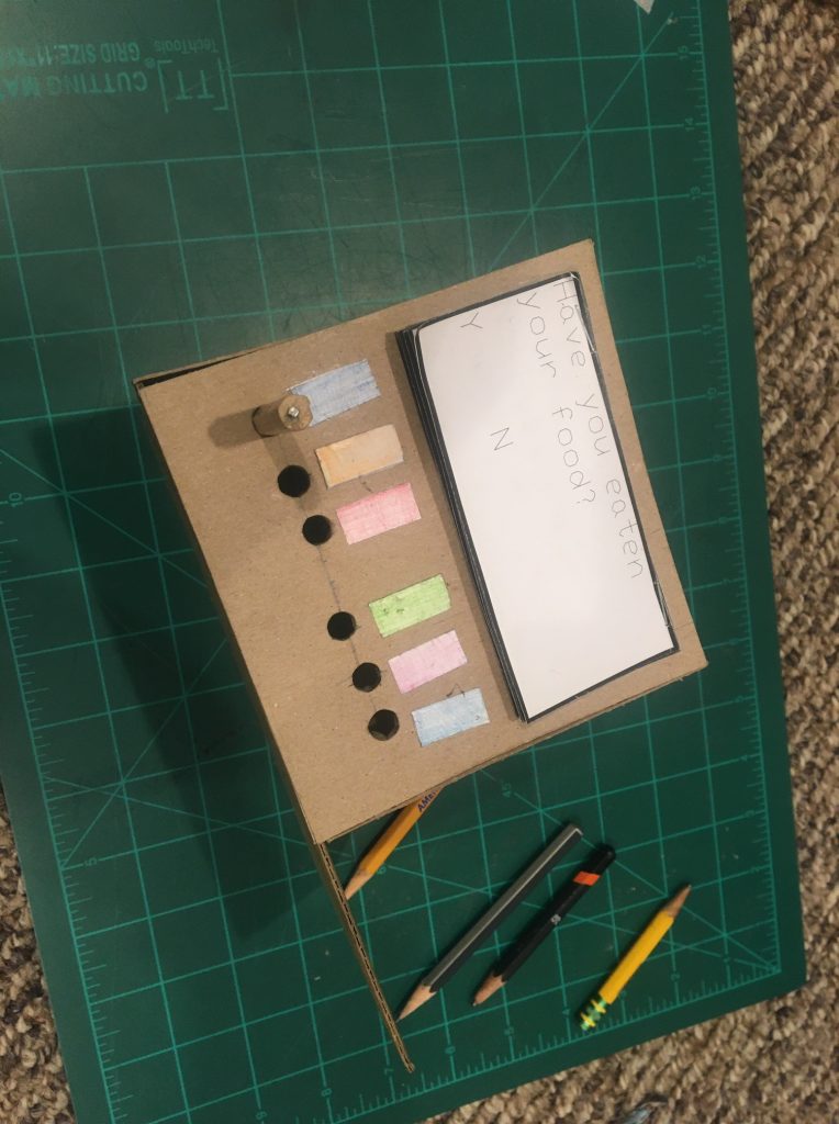
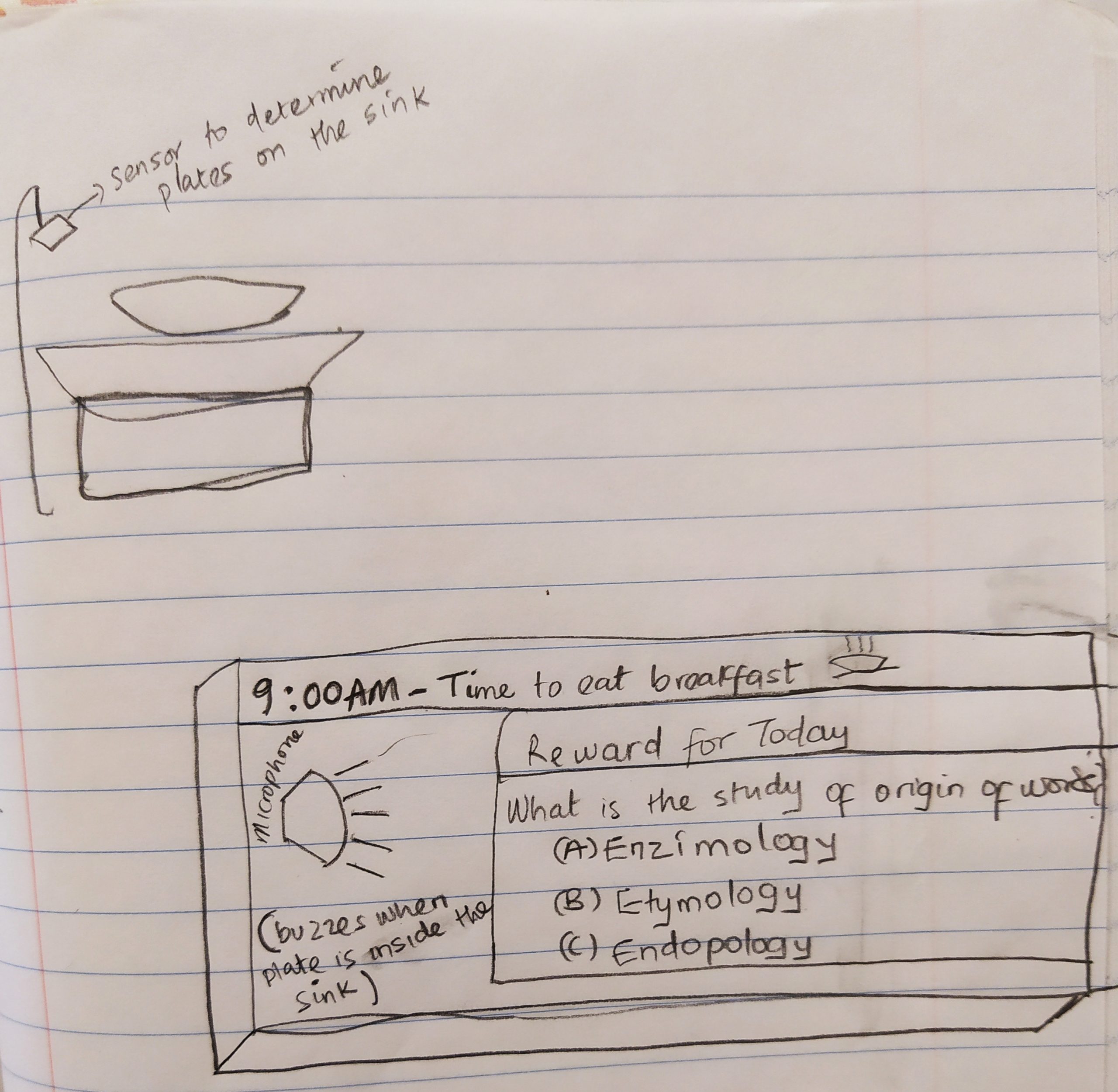
This prototype was made to answer the question of how the device is interacted with. This prototype was made with paper, pencils, and chipboard. The front-facing panel of the prototype contains the screen, which is simulated with stapled sheets of paper, small buttons, represented by small colored pieces of paper, and control knobs, represented by pencils. On the right of the device is a cardboard surface meant to represent where our client might put his finished plate or bowl after eating.
Still Images
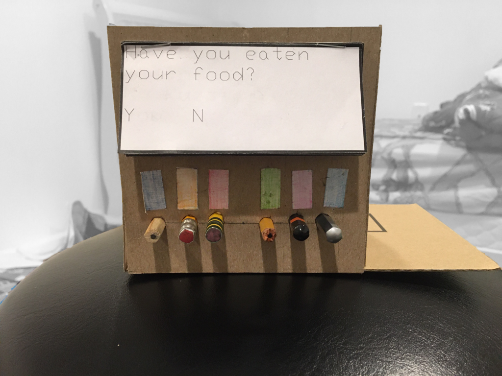
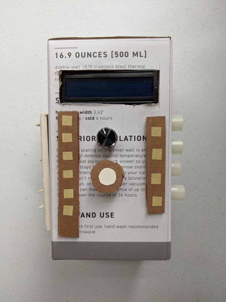
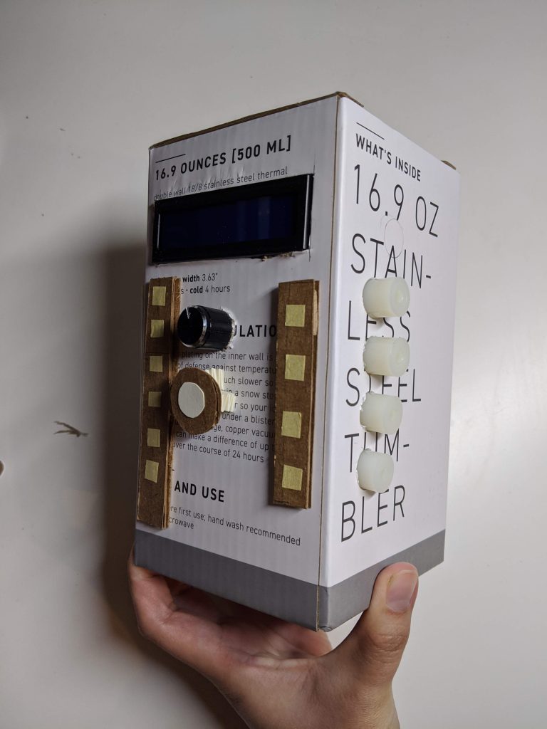
Overall view of Device
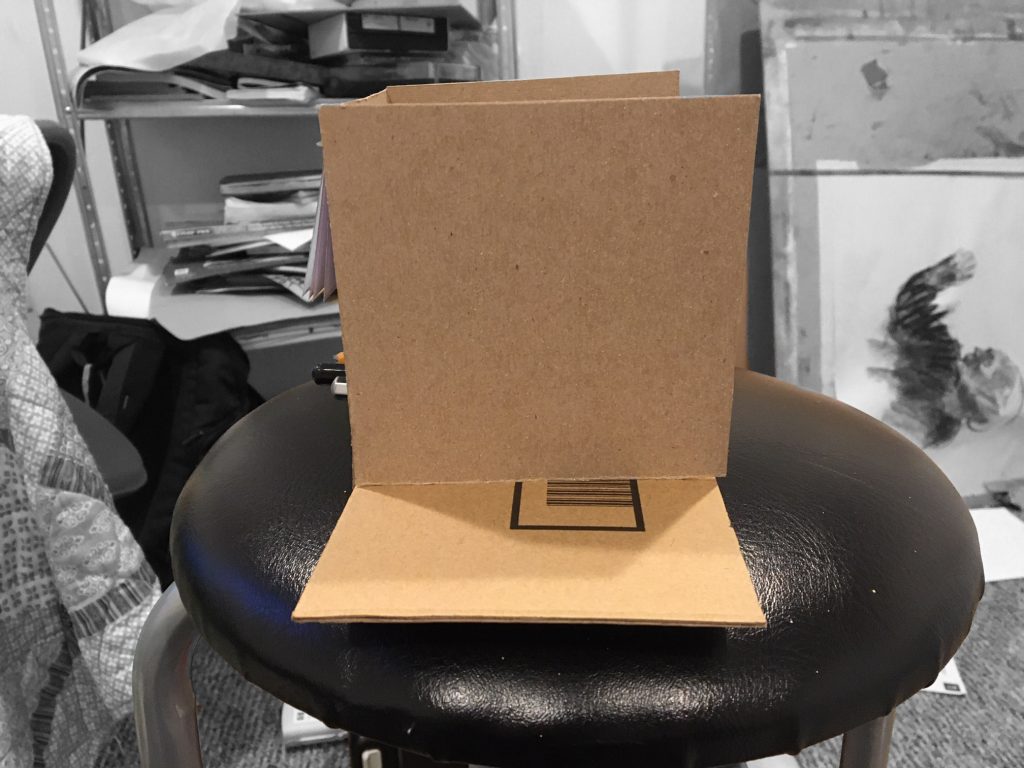
Cardboard “Sensor Plate”
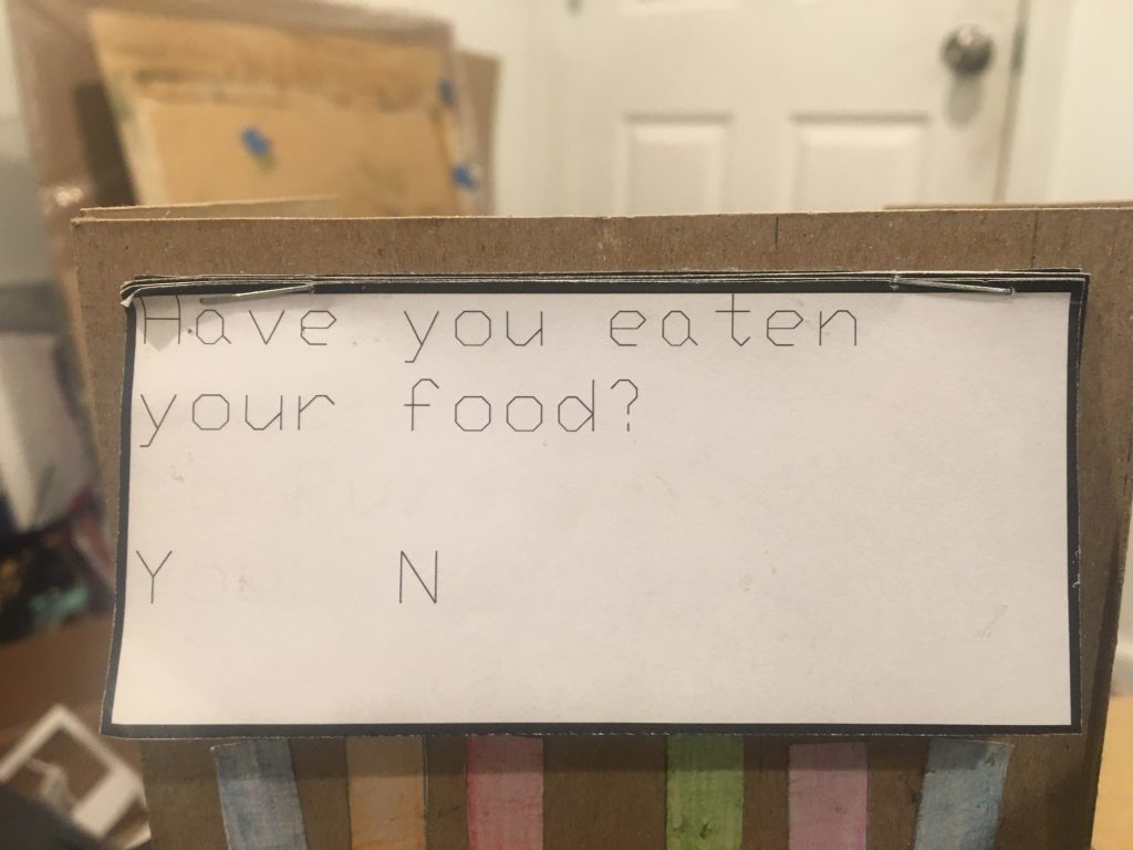
Close-up of paper “LCD Screen”
Moving Image
Gif of my mom interacting with the prototype
Process Images
Inserting pencil “potentiometers.”
Sketch of concept
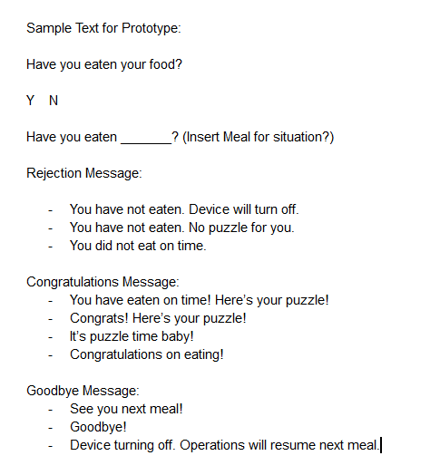
Screenshot of work-shopping some display messages.
Reflection
The purpose of my creation of an ergonomic prototype of our device was to ascertain if the device would be confusing visually. I wanted to know if the overall parts of the design, the interactive interface component and the sensor plate were designed in a clear, distinct, and intuitive way; additionally, I wanted to do an investigation into what makes a strong component layout. After demonstrating my device to my mother, I found that my design of the interface and sensor as an integrated device was intuitive. The low flat surface of the sensor plate made it a clear surface onto which the user of the device could place their dirty plate or bowl after they eat. She also informed me that the LCD messages were clear in their meaning and sequence in response to recognizing whether or not the user has eaten and in giving a puzzle as a reward. However, she felt that while the layout of the buttons and knobs were visually appealing and organized, the amount of components as well as their close proximity to each other made for an un-intuitive interaction. This point was reiterated within our Team’s discussion with Yale following our presentation on April 6.
All of the feedback I received was essential to improving the team’s design of our device. As such, I do not plan on ignoring any of the feedback I was given. In response to the feedback, one of my primary concerns currently is improving and distilling the layout of the interactive components so that they are intuitive and easy for Yale to use. The feedback I received in response to the prototype was expected and incredibly useful, and I hope to utilize it to move forward with our design in a positive direction.
Engineering prototype
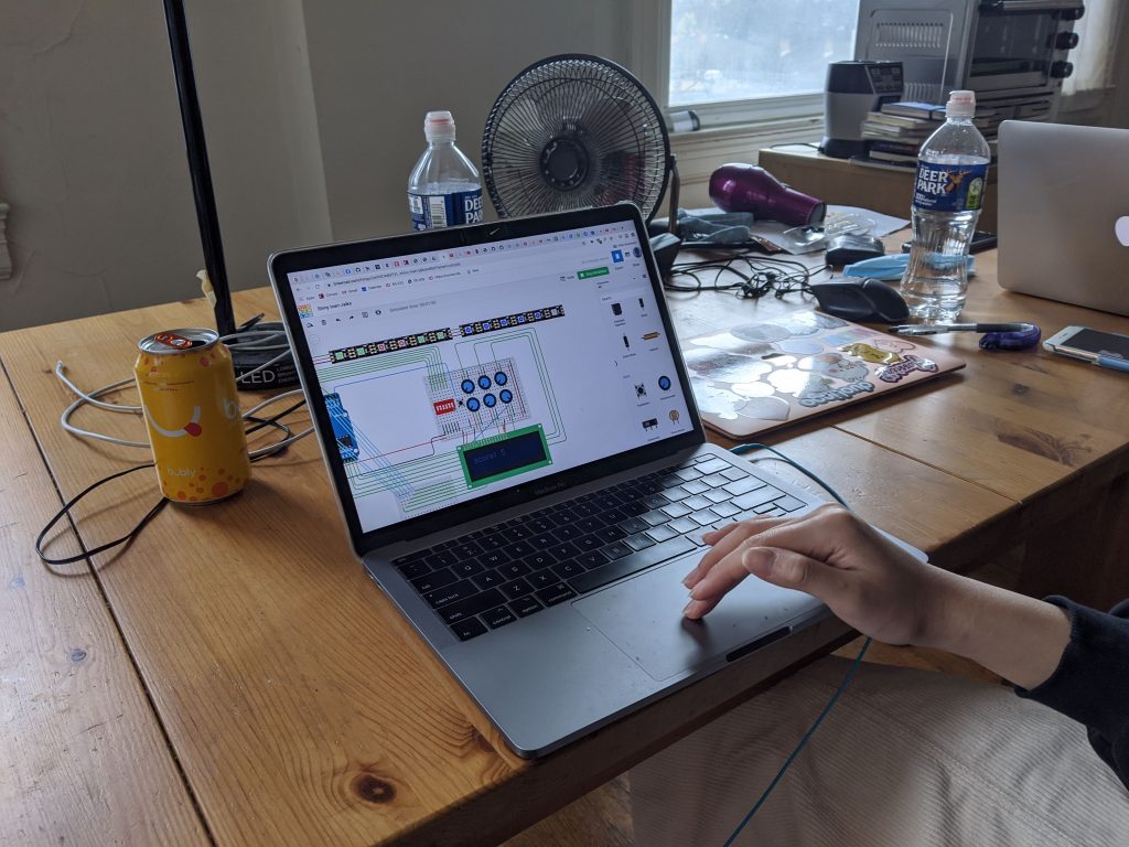
The engineering prototype was designed to describe the placement and the functionality of the ultrasonic sensor to detect the positioning of the plate. The prototype consist of five (5) major components : arduino board, breadboard, buzzer, ultrasonic distance sensor (to sense the distance of the plate), and the 16 x 2 liquid crystal display(lcd).
Still Image
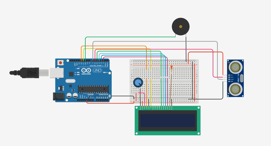
Overall circuit design

Buzzer

16 x 2 lcd
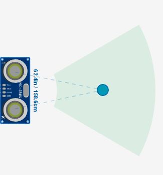
Ultrasonic distance sensor
Moving Image
The video shows how the circuit works: The sensor first senses the distance of the plates to the sensor. If the distance is less than 20cm, and the timing of the object is (in this prototype scenario) less than 10 secs, the buzzer buzzes and displays a message on the lcd to remind Yale to wash his plates.
Process Image
Design sketch
The videos below showed the critiques from two people.
/*
  LiquidCrystal Library - Hello World

 Demonstrates the use a 16x2 LCD display.  The LiquidCrystal
 library works with all LCD displays that are compatible with the
 Hitachi HD44780 driver. There are many of them out there, and you
 can usually tell them by the 16-pin interface.

 This sketch prints "Hello World!" to the LCD
 and shows the time.

  The circuit:
 * LCD RS pin to digital pin 12
 * LCD Enable pin to digital pin 11
 * LCD D4 pin to digital pin 5
 * LCD D5 pin to digital pin 4
 * LCD D6 pin to digital pin 3
 * LCD D7 pin to digital pin 2
 * LCD R/W pin to ground
 * LCD VSS pin to ground
 * LCD VCC pin to 5V
 * 10K resistor:
 * ends to +5V and ground
 * wiper to LCD VO pin (pin 3)

 Library originally added 18 Apr 2008
 by David A. Mellis
 library modified 5 Jul 2009
 by Limor Fried (http://www.ladyada.net)
 example added 9 Jul 2009
 by Tom Igoe
 modified 22 Nov 2010
 by Tom Igoe

 This example code is in the public domain.

 http://www.arduino.cc/en/Tutorial/LiquidCrystal
 */

// include the library code:
#include <LiquidCrystal.h>

// initialize the library with the numbers of the interface pins
LiquidCrystal lcd(12, 11, 5, 4, 3, 2);

const int trigPin = 6;
const int echoPin = 7;
int const buzzPin = 10;
long duration = 0;
int distance = 0;


void setup() {
  // set up the LCD's number of columns and rows:
  lcd.begin(16, 2);
  // Print a message to the LCD.
  lcd.print("hello, world!");

  // setting the trigpin as output and echo pin as input
  pinMode(trigPin, OUTPUT);
  pinMode(echoPin, INPUT);
   pinMode(buzzPin, OUTPUT); // buzz pin is output to control buzzering
  Serial.begin(9600);
}

void loop() {
  // set the cursor to column 0, line 1
  lcd.setCursor(0, 0); // Set the cursor on the first column and first row.
  lcd.print("Gd morning Yale!"); // Print the string "Good morning Yale!"
  lcd.setCursor(0, 1); //Set the cursor on the third column and the second row (counting starts at 0!).
  lcd.print("Time 4 breakfast");

// Clears the trigPin by setting it to LOW
  digitalWrite(trigPin, LOW);
  delayMicroseconds(2);
  // Sets the trigPin on HIGH state for 30 micro seconds
  digitalWrite(trigPin, HIGH);
  delayMicroseconds(30);
  digitalWrite(trigPin, LOW);
  // Reads the echoPin, returns the sound wave travel time in microseconds
  duration = pulseIn(echoPin, HIGH);
  // Calculating the distance
  distance = duration * 0.034 / 2;
  // Prints the distance on the Serial Monitor
  Serial.println((String)"Distance: " + distance + " cm");


  if (distance <= 10) {

    lcd.clear();
    lcd.setCursor(0, 0);
    lcd.print("Wash your plates");
    delay(5000);

    digitalWrite(buzzPin, HIGH);   // Buzz
    delay(60);

    digitalWrite(buzzPin, LOW);  // Don't buzz
    delay(60);

    lcd.clear();
    lcd.setCursor(0, 0);
    lcd.print("Reward 4 Today:");
    lcd.setCursor(0, 1);
    lcd.print("Word: Etymology");
    delay(5000);
  }
}
Reflection
From the prototype, I was able to discover that as a team, it is better we focus more on helping Yale to improve his eating habit instead of his ‘washing dishes’ habit. Which also means that the logistics of trying to detect whether he is washing his hands or washing the plates will be eliminated and hence, focusing more on the sensor positioning. One of the critique also suggested that it would be more fancy if we can incorporate ‘word pronunciation’ into the game. Also, a delay function might be needed so that it gives some timing before buzzing when a plate is detected.
Also, about the parts used, one unexpected thing I discovered was that 16 x 4 lcd is not among the parts on tinkercad, hence the game message on the lcd had to be shortened in length.
Moving forward, as a team, we agreed that instead of detecting whether the plate is washed or not, it is better we focus more on when Yale has finished eating and places his plate near the sensor before giving him a game to play rather than when he has finished washing his plates.
Puzzle Reward
Ergonomic Prototype
The prototype is part of the puzzle reward that Yale would get once he completes his task of eating at the right time.
For the puzzle reward, Yale expressed the different things he is interested in – math puzzles, logic puzzles, word puzzles. We realized that he is interested in various puzzles and it is very accessible for him by searching on the internet. This was why we wanted to prototype something that was more unique given that we are able to work with mechanical parts. We thought of making a mechanical puzzle that would allow him some variety and hope that with the prototype, we would be able to understand whether he likes mechanical puzzles and whether it would be a good reward for him.
The first part of this prototype is an ergonomic prototype to explore different ways to place the mechanical components like switches, potentiometers, buttons and LCDs.
Still Images
front view of prototype
side view of the prototype to see the knobs

side view of the prototype showing the switches
Moving Images
Process Images
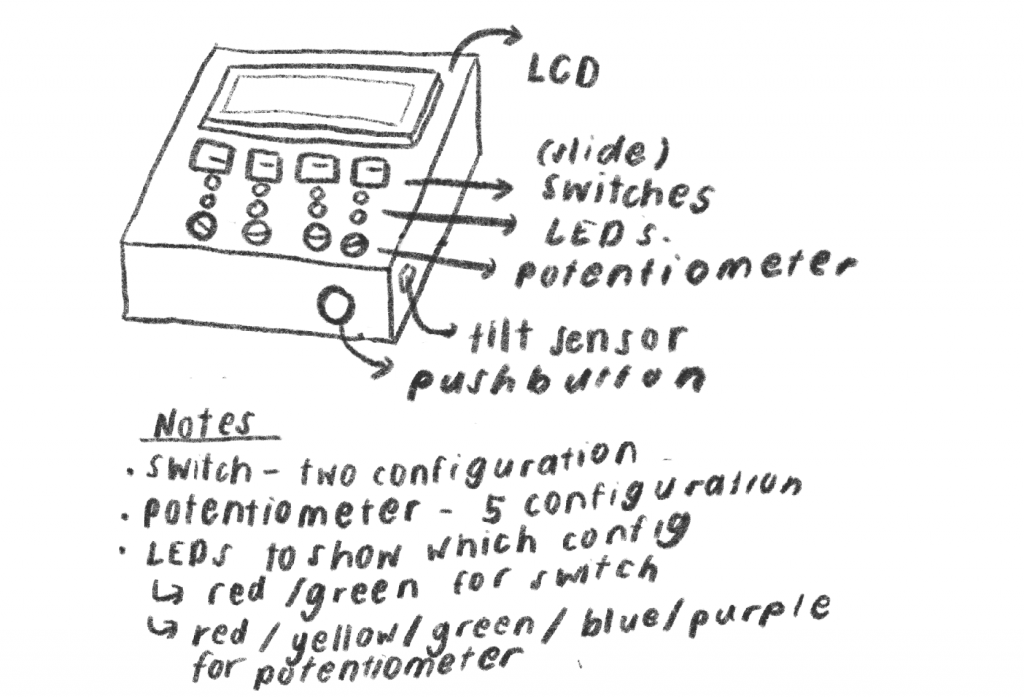
initial design sketch
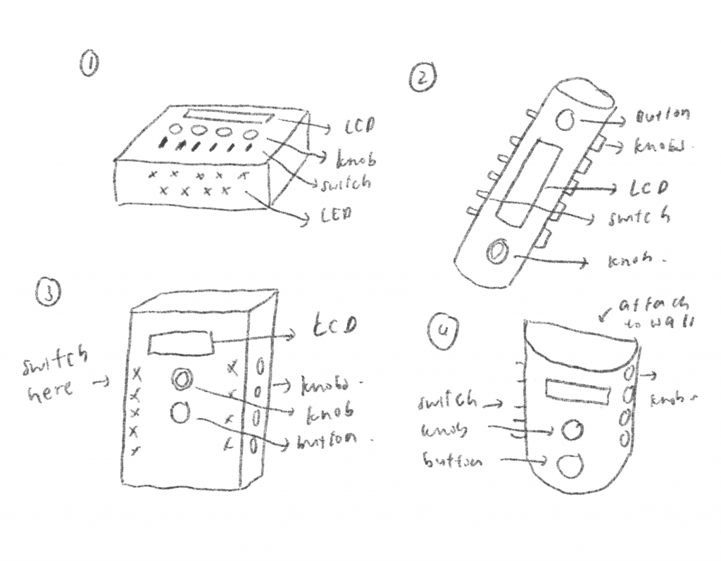
brainstorming sketches
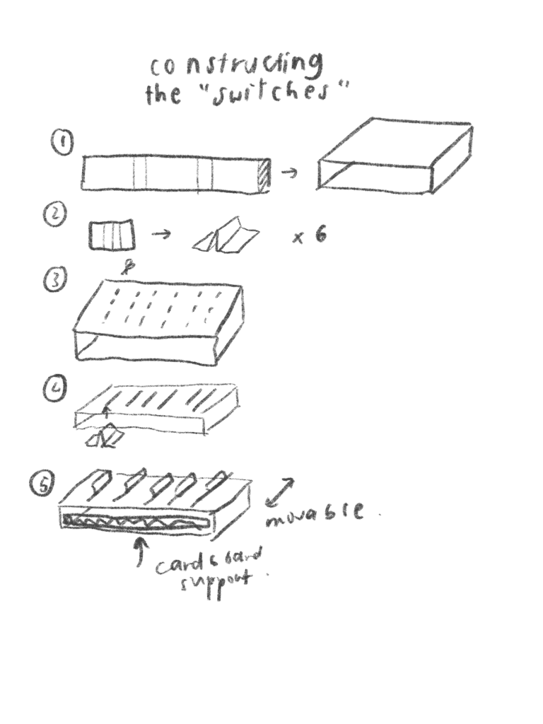
plan to prototype the switch component
Reflection
From the prototyping process of the ergonomic prototype, I realise that depending on the person using the device, there should be more distance between the potentiometer knobs. This is so that it would be less likely for the adjacent knobs to be affected when a knob is being moved. When testing out the prototype with two other people, I realised that one of them had a much easier time because her fingers were slimmer. The other person found it harder to be able to control each knob.
Users like the front facing part of the box are very simple and contain elements that would change the LCD screen, which includes one knob and one button. Users like this simplicity and that all the switches and knobs were not in the way. Users also comment on how it is a good idea to change the color of the LED based on the configuration of the components, like whether the switch is on or off. This is so that users would not have to constantly rotate the box around when figuring the puzzle. A user commented that since more dexterity is needed for the knobs, it is a good idea to have it on the right side, which is most people’s dominant hand. This would be something we would have to talk to Yale about to confirm.
One point brought up was that the switches were slightly harder to work with and does require more effort. This is something concerning if students are already having problems with using the switches, it would be way harder for Yale to work with the switches.
Engineering Prototype
The prototype is part of the puzzle reward that Yale would get once he completes his task of eating at the right time.
The second part of this prototype is an engineering prototype to explore the potential of using a mechanical puzzle as a reward for Yale. It is also a form of exploration of the possibility of a mechanical puzzle since it is not something that is readily available in the market.
Still Image
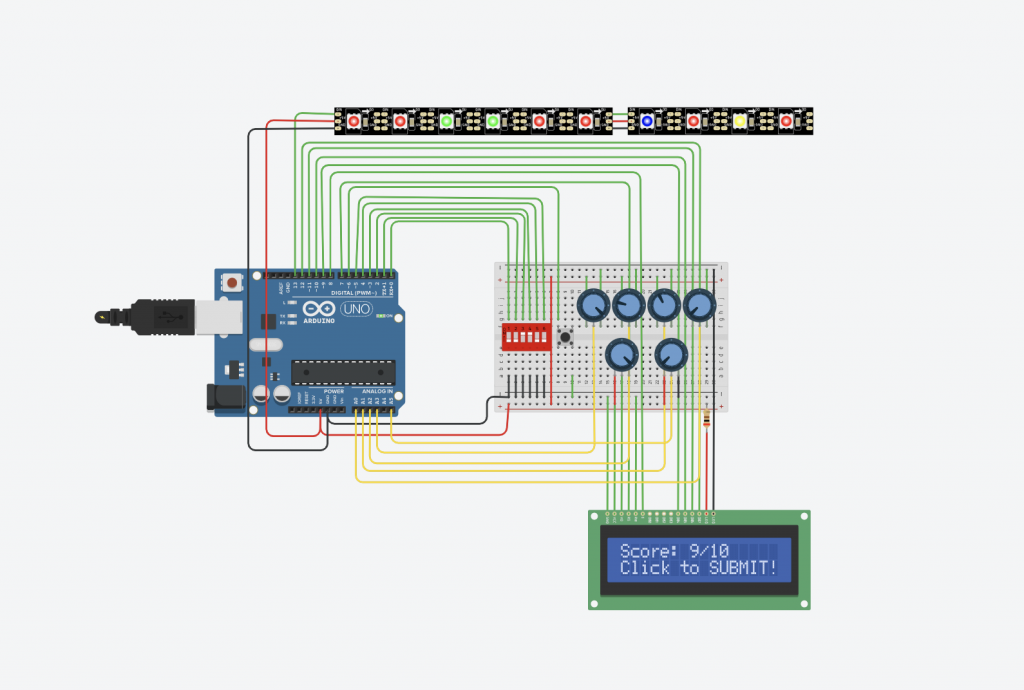
overall layout
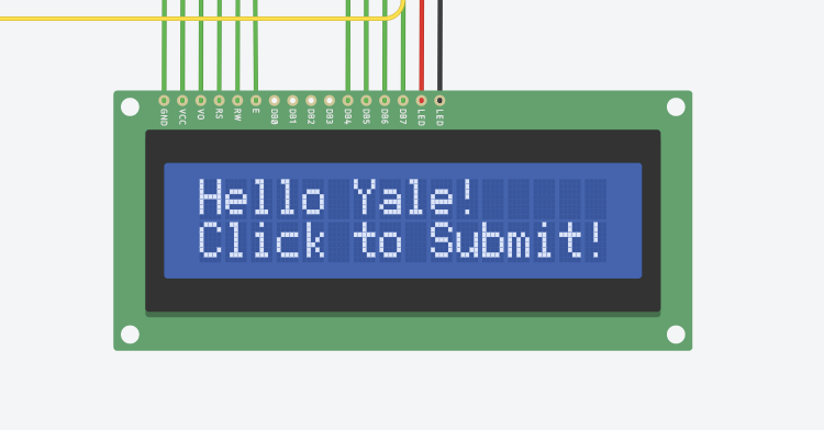
welcome screen
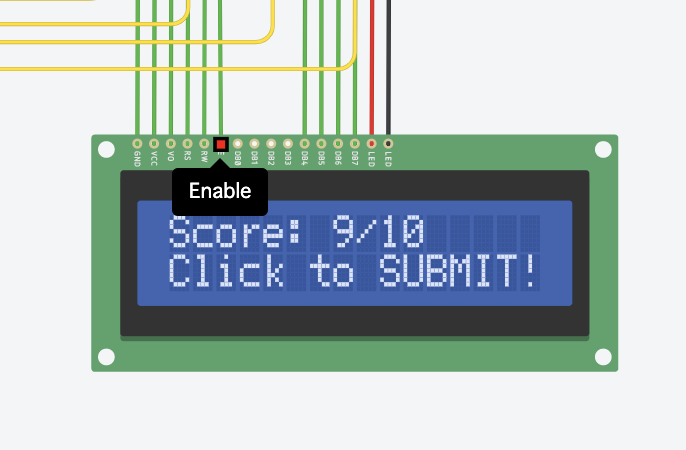
score screen

led lights as indicators
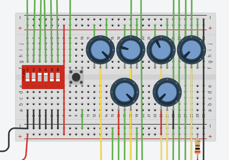
knobs and switches
Moving Image
interaction of switches
interaction of knobs
Process Images
user testing
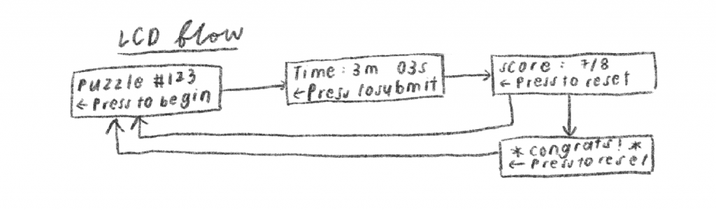
lcd design flow sketch
#include <Adafruit_NeoPixel.h>
#include <LiquidCrystal.h>

#define PIN 13   // input pin Neopixel is attached to
#define NUMPIXELS      10 // number of neopixels in strip

Adafruit_NeoPixel pixels = Adafruit_NeoPixel(NUMPIXELS, PIN, NEO_GRB + NEO_KHZ800);

// COLOR THINGS
const uint32_t  RED = pixels.Color(255, 0, 0);
const uint32_t  YELLOW = pixels.Color(255, 255, 0);
const uint32_t  GREEN = pixels.Color(0, 255, 0);
const uint32_t  BLUE = pixels.Color(0, 0, 255);

// SWITCH THINGS
const int SWITCH_ONE = 0;
const int SWITCH_TWO = 1;
const int SWITCH_THREE = 2;
const int SWITCH_FOUR = 3;
const int SWITCH_FIVE = 4;
const int SWITCH_SIX = 5;
int switchPins[] = {SWITCH_ONE, SWITCH_TWO, SWITCH_THREE, SWITCH_FOUR, SWITCH_FIVE, SWITCH_SIX};
const int NUM_SWITCHES = 6;

// POTENTIOMETER THINGS
const int POT_ONE = A3;
const int POT_TWO = A2;
const int POT_THREE = A1;
const int POT_FOUR = A0;
int potPins[] = {POT_ONE, POT_TWO, POT_THREE, POT_FOUR};
const int NUM_POT = 4;

// BUTTON/ QUIZ THINGS
/*
const int POT_PIN = A5;
const int BUTTON_PIN = 6;
int answer[] = [HIGH, HIGH, LOW, LOW, HIGH, HIGH, 0, 1, 2, 3];
*/
// initialize the library with the numbers of the interface pins
LiquidCrystal lcd(7, 8, 9, 10, 11, 12);

void setup() {
  pixels.begin();

  // set up the LCD's number of columns and rows:
  lcd.begin(16, 2);
  // Print a message to the LCD.
  lcd.print("hello, world!");

  // SETUP SWITCHES
  for (int i = 0; i < NUM_SWITCHES; i ++) {
    pinMode(switchPins[i], INPUT_PULLUP);
  }

  // SETUP POTENTIOMETERS
  for (int i = 0; i < NUM_POT; i ++) {
    pinMode(potPins[i], INPUT);
  }
}

void loop() {
  lcd.setCursor(0, 1);
  lcd.print(millis() / 1000);

  for (int i = 0; i < NUM_SWITCHES; i ++) {
    if (digitalRead(switchPins[i]) == LOW) {
      pixels.setPixelColor(i, GREEN);
    } else {
      pixels.setPixelColor(i, RED);
    }
  }

  for (int i = 0; i < NUM_POT; i ++) {
    int potLEDPos = i + NUM_SWITCHES;
    int potReading = analogRead(potPins[i]);
    if (potReading > 256 * 3) {
      pixels.setPixelColor(potLEDPos, RED);
    } else if (potReading > 256 * 2) {
      pixels.setPixelColor(potLEDPos, YELLOW);
    } else if (potReading > 256) {
      pixels.setPixelColor(potLEDPos, GREEN);
    } else {
      pixels.setPixelColor(potLEDPos, BLUE);
    }
  }
  pixels.show();
}
Reflection
The prototyping process of the engineering prototype was not very smooth for a few reasons. The first was because the simulation was very far from real time and it was hard to see the process of trying out different combinations. Without the tactile elements of turning a knob and flipping a switch, it felt less satisfying and also made the process longer and harder.
One approach the user took when solving the puzzle was to guess every single combination. This was not ideal because it would not be a puzzle but more on a tedious task that takes more time than brain power. Given this suggestion, we plan to limit the number of guesses so that Yale would have to think of smart ways to solve the puzzle. With the limitations of the tinkercad software, it is hard to have multiple LCD screens, which is why labels should be made to explicitly specify the purpose of each button. One small comment on our initial prototype was that the maximum score was not displayed so the user did not know whether the problem was solved or not. In order to address this issue, we decided to add the maximum possible score and have the button reset the puzzle when full marks are achieved.
Final Thoughts
Overall, we feel that the prototyping process was very useful in terms of getting the ball rolling and getting a sense of the feasibility and desirability of our project. It was really useful to prototype the mechanical prototype because it was something that we were not sure would be a viable puzzle project to be used a a reward for Yale. When we met Yale over the week, we managed to show him the prototype and get some initial feedback before we move on. We think that this fail fast principle would work best in the long run and prevent us from wasting time working on something that would not meet the needs and solve problems that Yale is facing.
The biggest challenge when prototyping remotely is that communication of ideas is harder. Anishwar and Zoe were working on ergonomic prototypes and since it was hard to verbally express how they would like their prototype to look like. Anishwar was not sure how exactly the mechanical puzzle worked which was why it was slightly harder to convey the entire idea through words and images. Similarly, the task idea of detecting a plate could be implemented in different ways. It was very difficult to convey the initial idea of the brainstorming to the person prototyping the product. When working remotely with the client, it was also harder to get a sense of whether the client likes the idea. Yale was very polite and constantly praised our efforts, which was encouraging but was not very useful in terms of getting criticism on how to improve our product. It was also hard to get him to interact with the ergonomic prototype to see whether there are any difficulties moving different components.
We decided to have each team member be in charge of a single portion of the project – Ola will be working on the code for the task sensor, Zoe will be working on the code for the puzzles and Anishwar will be working on the visuals of the prototype. This gives the team members more ownership but it is harder to keep each other accountable. Also, one risk we might face is that if one portion of the project is more time consuming, the amount of work done by each member might not be equal.
One thing we hope to do differently in the future is having more communication. Even though we would have video calls outside of class time, it was still very hard to communicate ideas through video calls. I think having the habit of quickly sketching is extremely important.
Comments are closed.