Introduction
For the final project of Introduction to Physical Computing, we were tasked with building an assistive device for an elderly OSHER student. Within the scope of Arduino programing and design, we were to solve a personal problem for our client through custom designs. We were introduced to our client Diane, a former teacher who works as a docent at the Pittsburgh Museum of Natural History. Through interviews with Diane and discussion among the team, we landed on the ideation and creation of a wearable metronome bracelet for Diane to help her combat her tendencies to speed up or rush.
However, due to the major world event that is the COVID-19 pandemic, the final project had to be virtualize. Instead of creating a final tangible product, we will be creating the circuitry through simulations, and CAD modelings. This limitation leads to some uncertainties in our design that can be seen throughout the documentation.
The Final Metronome Bracelet
Our team made a metronome bracelet, which vibrates based on a beat that that Diane sets. It helps Diane from restlessness and lets her focus better on what she is doing. She enjoys doing pilates, so we intend to make this in silicone, so that it is waterproof. We worked very hard to fulfill the clean, “cool” design aspect of this device to avoid the medical-device-esque design as Diane wanted.

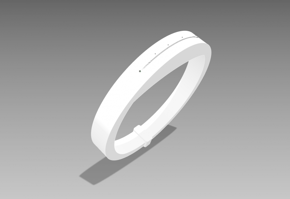
The overall view of the product
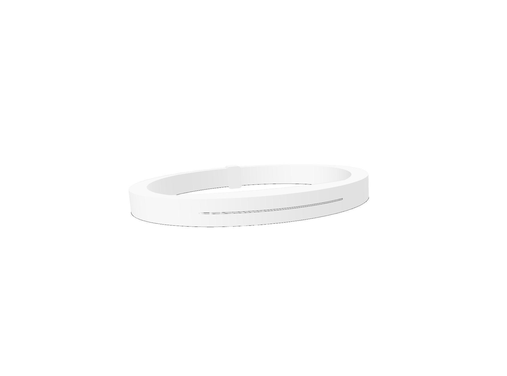
The front view of the final product
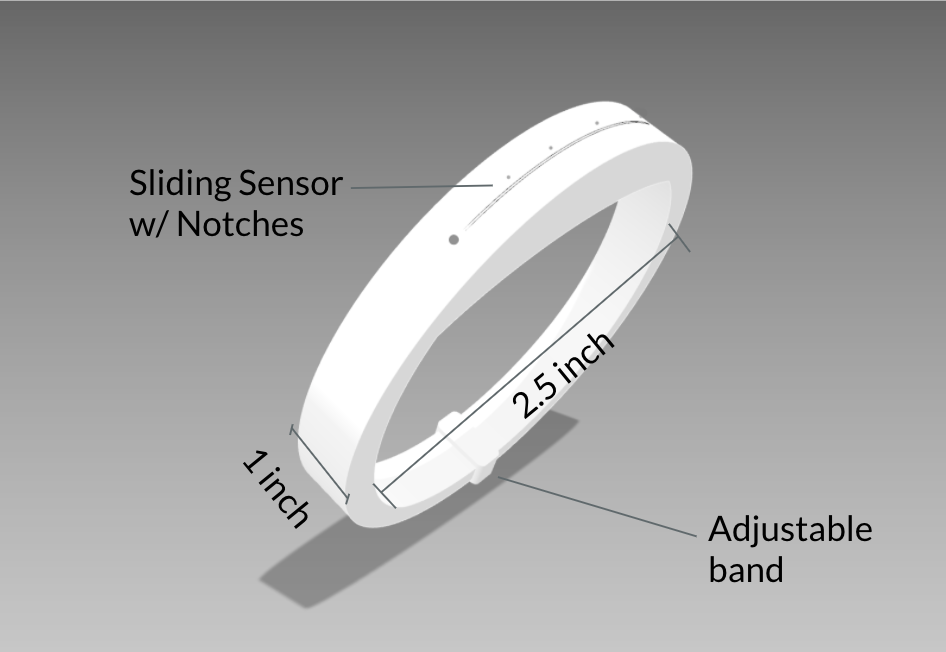
The dimensions of the model
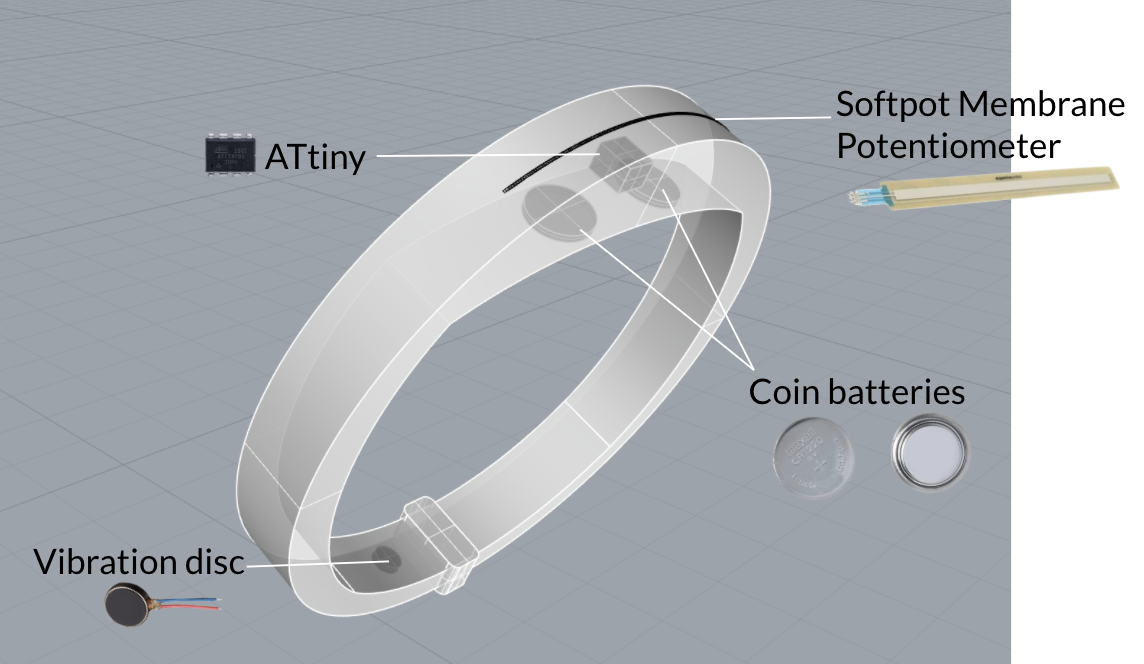
See-through view for the parts
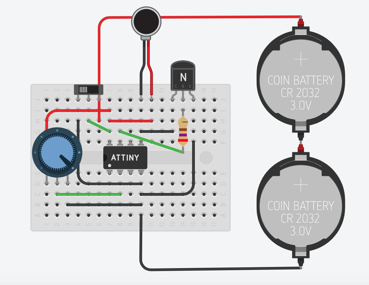
The wiring of the parts
Tinkercad interactions
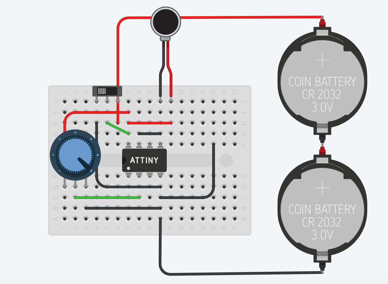
important to note the presence of the breadboard is not a part of the final design. It was implemented to make clear the connections.
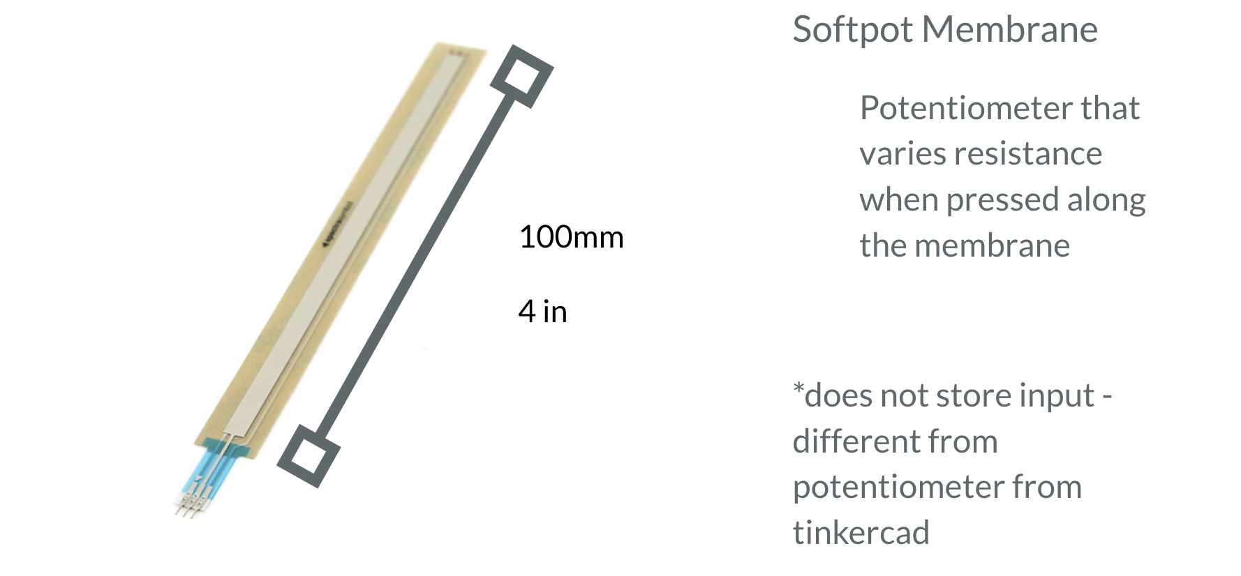
Once the power is turned one, the user can control the frequency of the vibration. Note that the design requires us to us a Softpot Membrane instead of a normal potentiometer. However, due to Tinkercad’s simulation limitation, this is the closest alternative. The Softpot Membrane can be seen here:
https://www.sparkfun.com/products/retired/8607
PHYSICAL MOCKUP
Note that this was made to test the behaves-like prototype in person. As such, the prototype is much rougher than the final rendering.
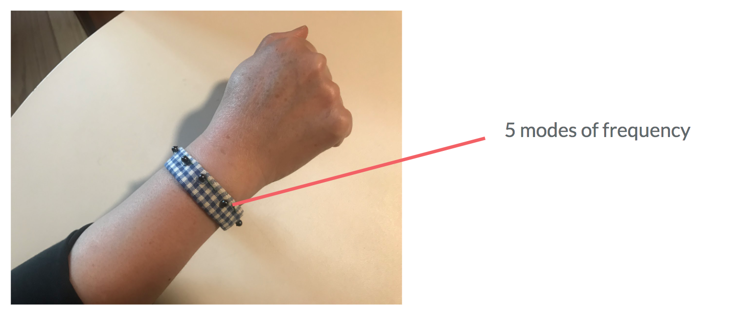
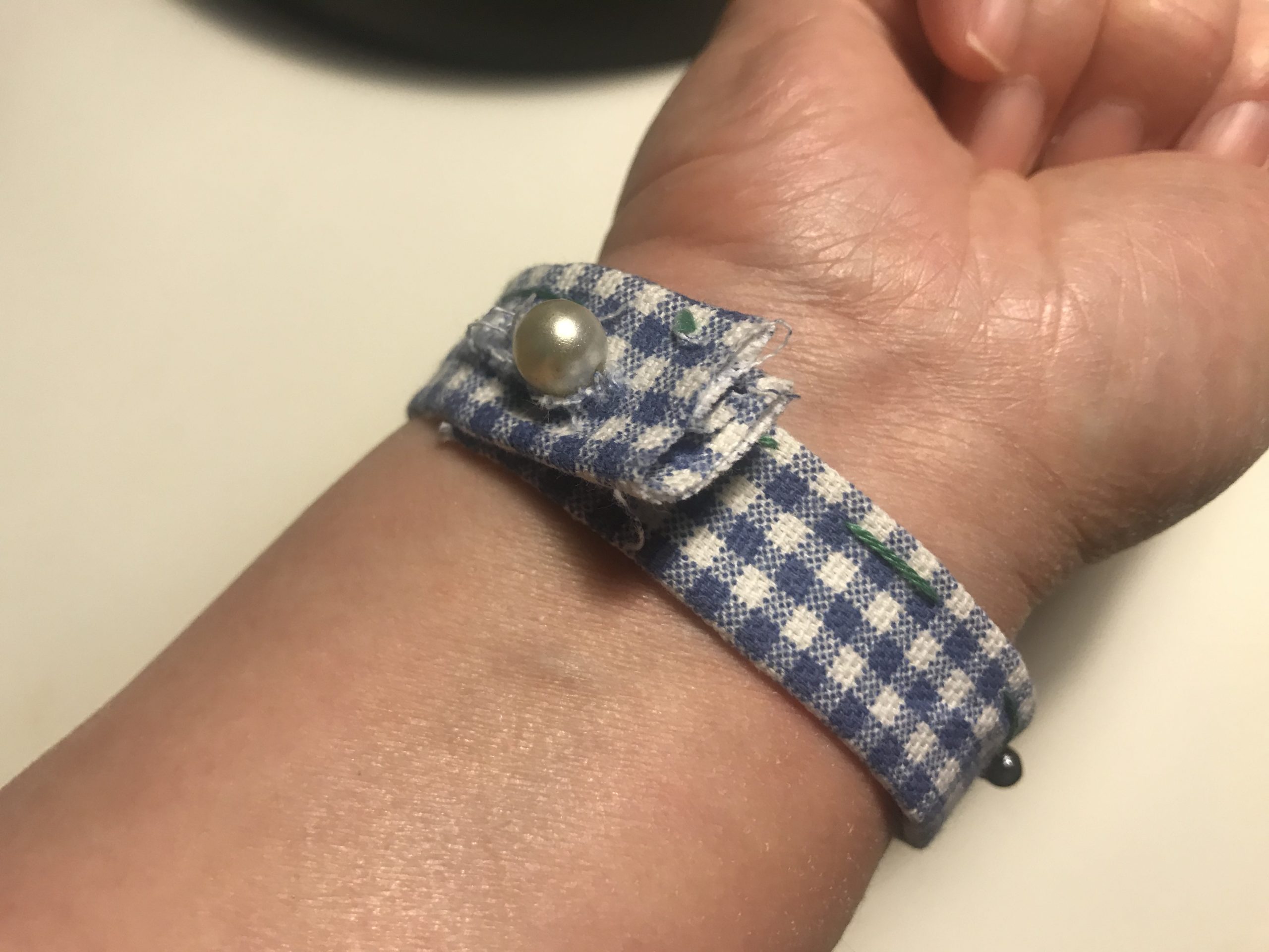
Overall look of the bracelet. It has 5 small extruded braille dots (simulated through buttons on fabric). These buttons can change the frequency of beats, depending on where Diane touches them.
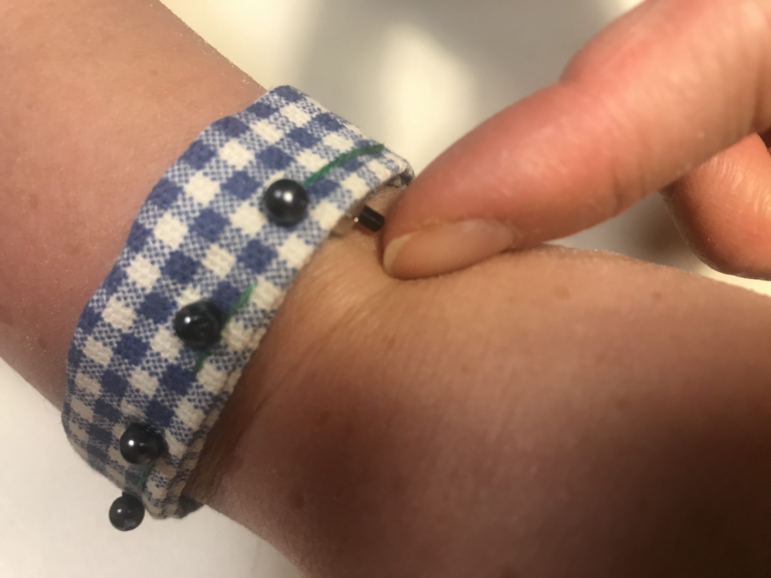
How Diane should interact with the bracelet. Note that the braille dots are much bigger than the actual design. These were the smallest button that I had access to in the house
Slide switch for Diane to turn on and off the bracelet. Located at the end of the button range to indicate orientation of the bracelet.
“Clasp” for Diane to adjust the length of the bracelet. Note that this is a button only for physical prototyping. This would ideally be a clasp, as indicated in the final rendering.
THE NARRATIVE SKETCH
Diane is giving a crowd a tour inside the museum. As she explains the rhythms and strokes of a painting, she notices herself speeding up. But she is not sure if that is just her thought, or if she is actually talking fast. She gives a single touch under her sleeve. The bracelet quietly gives her the beats in her personalized tempo that she can pace herself to. She finishes the presentation.
Diane goes to her pilates class. The instructor tells Diane that this position requires certain pace of breathing. The instructor says “inhale on one, two, three,” yet her breathing seems to be tangled at a certain beat. Diane touches her bracelet; this time, different from the museum tour, she adjusts the beat to a slower tempo. The instructor has no idea what kind of magic this bracelet does. She does not even think that it is a medical device, because it looks so cool! Diane finishes her class successfully.
The Process
From our last prototype, our project took a big shift after talking with Diane about what she would like to see in our design. While Diane was pleased with the aesthetics of the bracelet (She emphasized that this was very important to her), she didn’t find the bracelet’s custom frequency feature to be very useful. Rather, she was more interested in having set frequencies to shift through. She preferred having around 5 modes, ranging from fast to slow.
With this new constraint, we researched new ways of interactive inputs beyond the simple button that we had previously worked with. After some digging, Ivan was able to find a part called a softpot potentiometer that worked well with our concept. This new part is a flexible potentiometer that takes in pressure inputs across a band. We found this to be perfect for Diane to wrap around her wrist and press along the band to get different frequency outputs.
Softpot potentiometer that Ivan found to be fitting for our project. It works similarly to a real potentiometer, where you can take in a range of inputs along the band.
With this, we broke down our tasks into three parts similar to the last phase. Elizabeth took the behavioral prototype, Chloe took the looks-like, and Ivan took the works-like. Since Elizabeth and Chloe’s work were interdependent on each other, Elizabeth’s work was frontloaded in the first week to hand off to Chloe in the next week. Our main goal was to be able to put all our parts together and receive feedback from Diane before presenting on the final day, so that we can adjust any minor issues prior to the presentation.
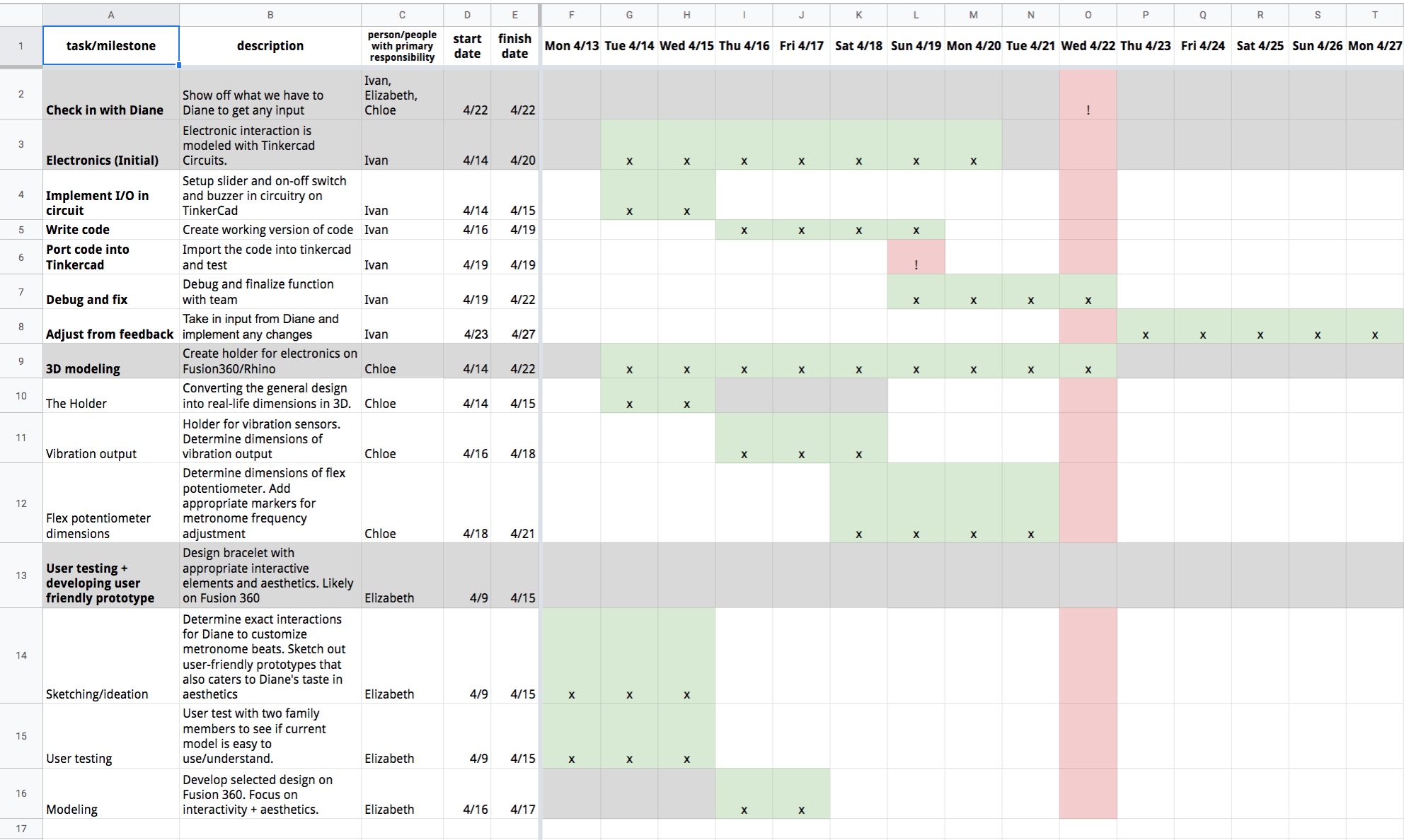
Our GANTT chart. Ivan – works-like. Chloe – looks-like. Elizabeth- behaves-like.
We were able to maintain the schedule and workflow quite well, despite our timeline being pushed back by a couple days. When we checked in with Diane, however, she asked for no revisions, as she was happy with how the prototype turned out, putting us back on schedule.
Behaves-like prototype
The behavioral prototype began with considering how Diane would most intuitively interact with the bracelet. One obvious, yet easy-to-miss finding was that: Even though the flex potentiometer can wrap all the way around Diane’s wrist, the top of the wrist (where the watch face would usually sit) was the only real estate that allowed interactions. The fact that the potentiometer can be the bracelet in itself was deceiving me to think that Diane can press any point in the entire bracelet. This finding was not realized until after wrapping some papers around my wrist to feel how the bracelet might feel.
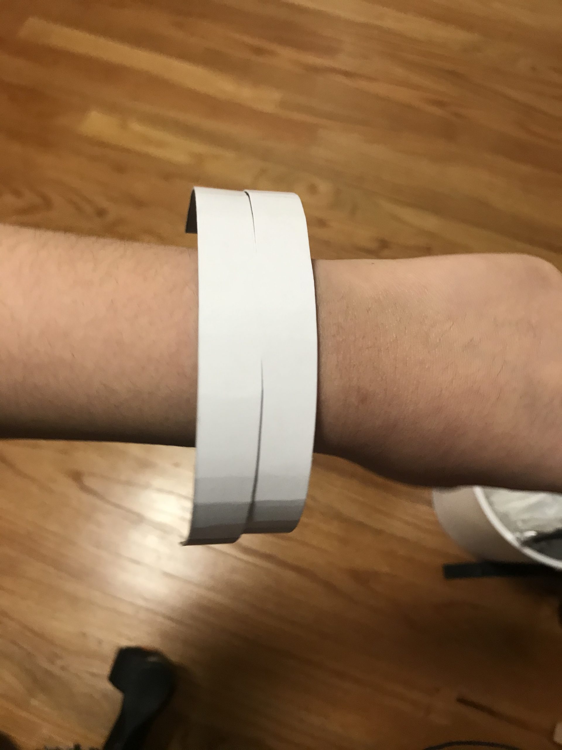
top of wrist is the only interface I can work with, contrary to prior belief that the whole bracelet can be a potentiometer
During this phase, I was flexible with exploring how to include different outputs other than the regular metronome that we had planned. One suggestion from Diane from our discussion was that she would like to see variations of beats to support her inhales and exhales during pilates. As such, I considered having two potentiometers stacked on top of each other, where the top is the regular metronome and the bottom is the irregular breathing version. After talking with my dad, he suggested a much simpler version, where you include a switch to change the two modes.
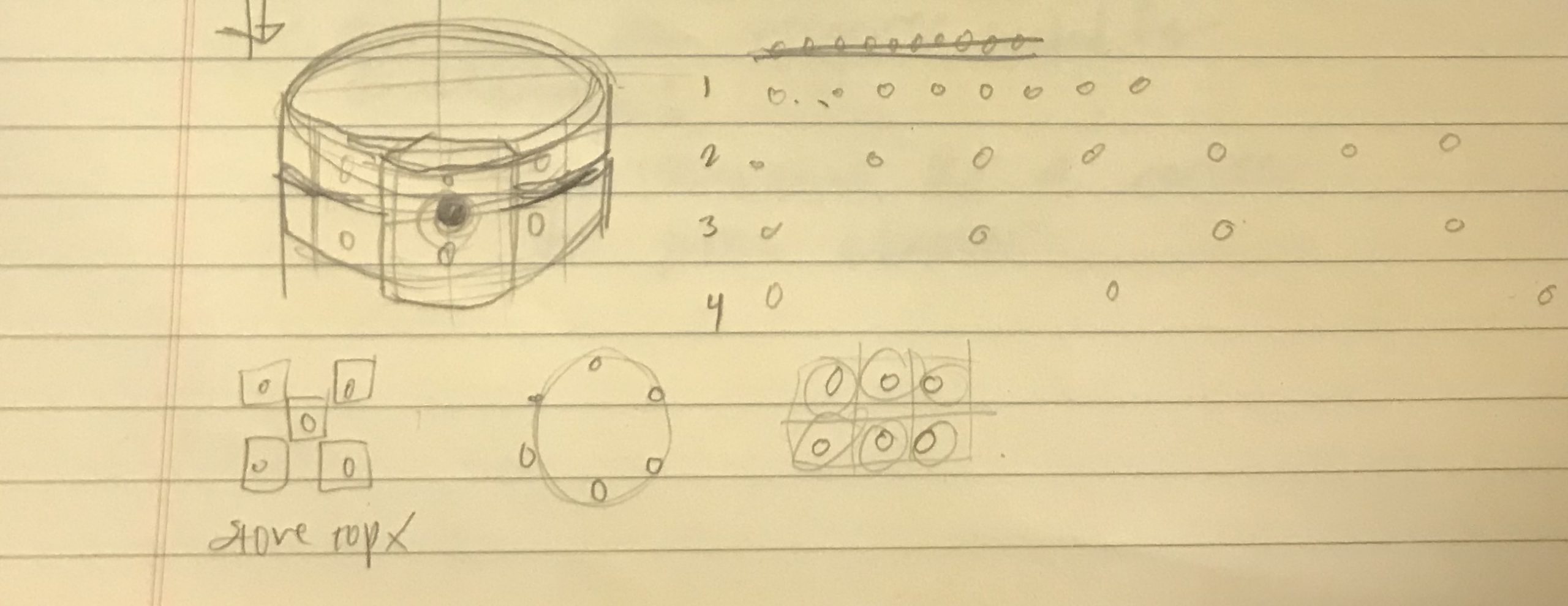
Sketch consideration for ergonomic layouts of buttons, as well as possibility of including a “breathing” version apart from the regular metronome
While this was thought about, Ivan brought up a good point that this irregular beats feature wouldn’t be very useful in different contexts of Diane’s life. As such, we simplified our features to its most essential part, so that it is clear, easy to use and lasting over time.
The first prototype came through a physical prototype using fabric and buttons. Main lessons from sketching the bracelet was that simplicity was crucial for a small interface. As such, I kept the bracelet quite simple with 5 buttons that would lay on top of the wrist.
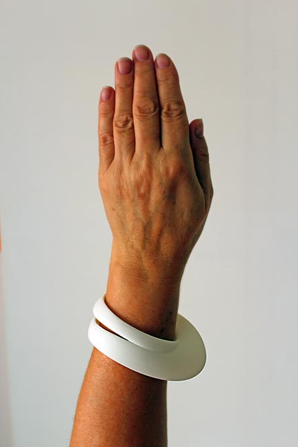
My mom testing out the bracelet. She found it very straightforward and easy to use
From testing the bracelet with my parents, and it revealed two following points:
- The band is simple and easy to understand.
- My mom wanted the metronome beat to be fast inside the wrist, and slow down away from their body, whereas my dad preferred the opposite. How do I indicate the orientation of the bracelet in an intuitive way?
With this feedback in mind, I proceeded to make the model in 3D modelling. While the last prototype dealt with clarity of interactions, I wanted the modelling to take one step further in becoming aesthetic, as Diane wants. As such, I looked into various parametric bracelets for inspiration. I found out that Rhino and Grasshopper were a particularly useful tool for this, so I decided to try them out.
Inspirations I found online of bracelets that take advantage of curve forms.
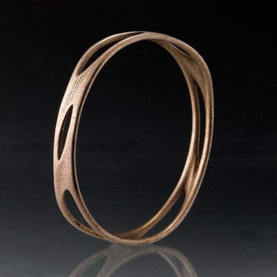
Inspirations I found online of bracelets that take advantage of curve forms.
[Source1:
Source2:
My initial attempt was on Grasshopper, to get a parametric control over the form of the bracelet. I was following this tutorial: https://www.youtube.com/watch?v=CDnTFb3BgVo
I had some problems with the initial steps, where the “polar points” component was acting oddly. Rather than creating an arc along the desired angle, the program was creating split arcs in full rotation. I couldn’t figure out how to fix this, so I decided to drop grasshopper for the time being.
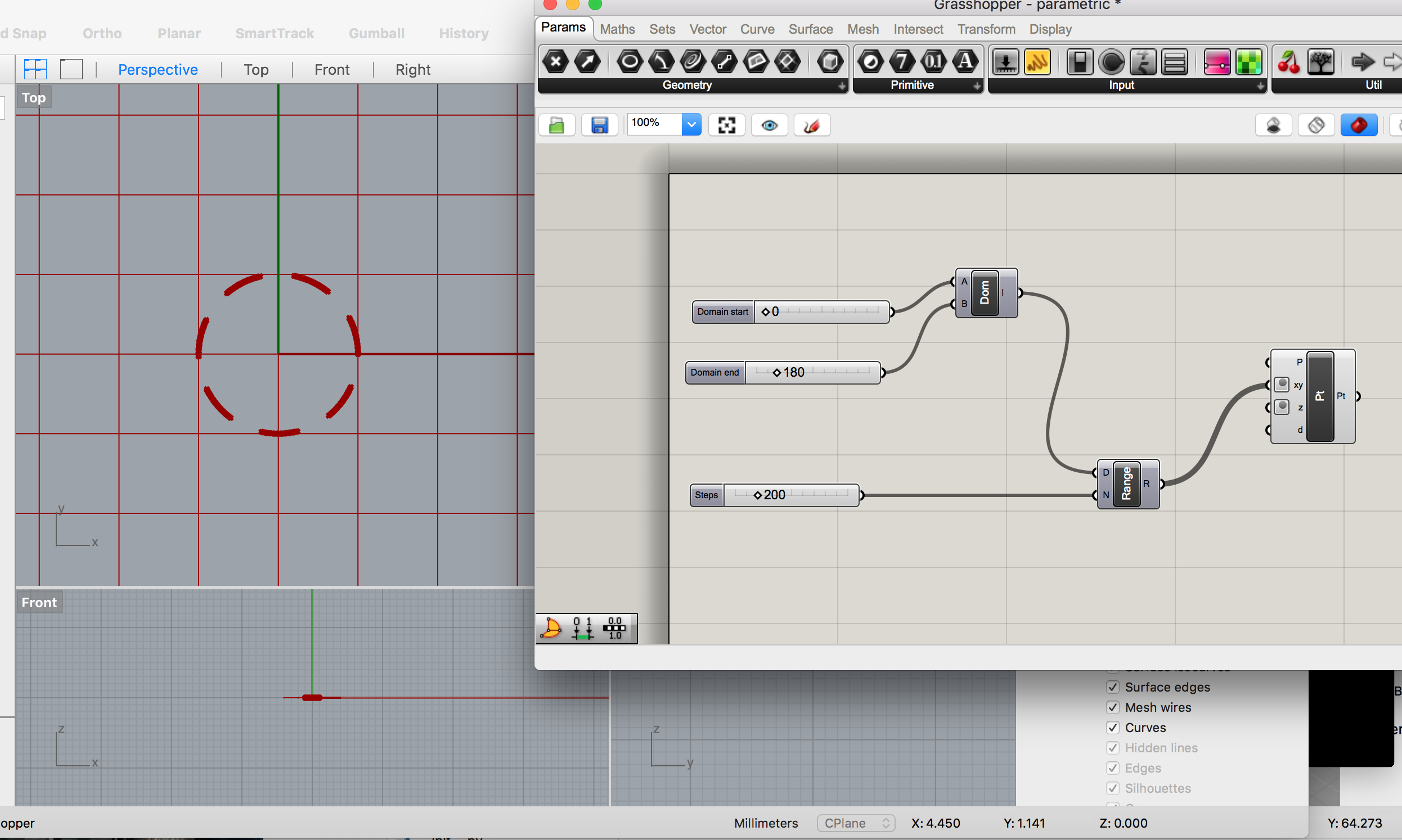
According to the tutorial, the resulting line should’ve been a line of connected dots along a curve, but my program instead created a series of disconnected lines along a circle.
After doing another round of searching, I found this tutorial to be the most helpful: https://www.youtube.com/watch?v=Q8Issn3Mpzs. It was simple enough to follow, but allowed variation of thickness along the bracelet, which was my primary goal.
Main problems came from my unfamiliarity with the software. For example, I spent a good thirty minutes trying to figure out why my line was not divided into points as described in the video. It turned out that my view settings were different from the tutorial, so I had to dig around on my own to see how to make the points appear.
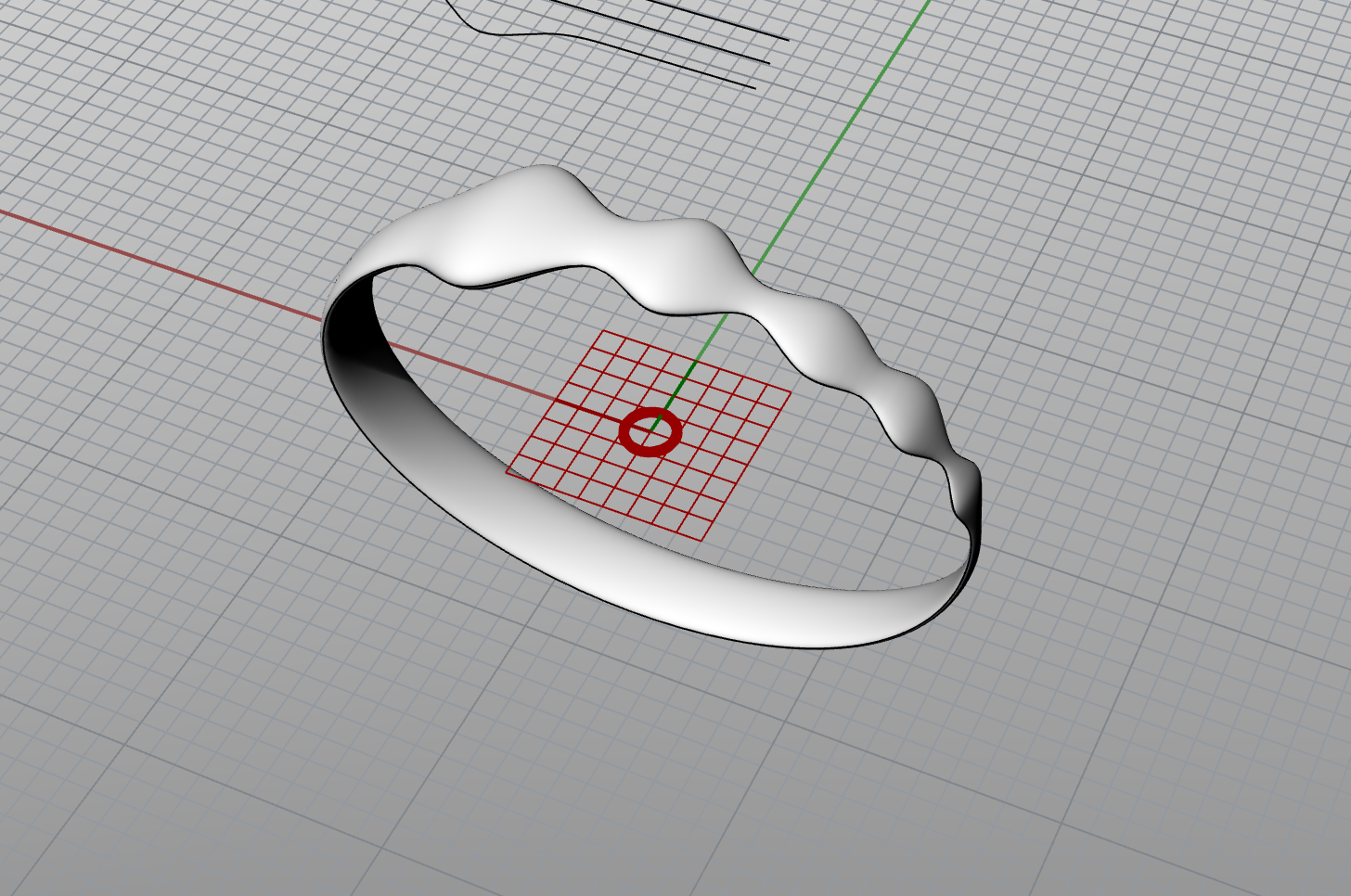
The final model. Big to small waves indicate that the frequency range goes from slow to fast. This addressed the orientation issue previously found in user testing.
While the process was quite slow as I was new to the program, I was happy with how the bracelet turned out. I liked the bulbs that formed in the waves, making it more tactile than the traditional bracelet we imagine. However, I didn’t give much attention to how electronics would be held inside, which was a critical issue that Chloe had to work around after I passed off the design to her.
Looks-like prototype
As for rendering the final model, Chloe’s main goal was to create a simple and compact design. While Elizabeth’s 3D prototype in Rhino fit the aesthetic goals, it didn’t meet the practical goals to build off of. For one, it was difficult to maintain the wavy form all the while holding all the electronics inside. Also, the thinnest parts of the bracelet would be prone to ripping, if the bracelet were to be made of silicone as intended. As such, Chloe remodelled the bracelet to be aesthetic in a simpler form. Main constraints came from making precise housing for the exact dimensions of each electronic part.
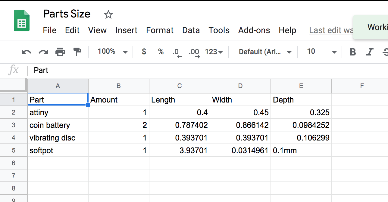
Chart of dimensions for each electronic part
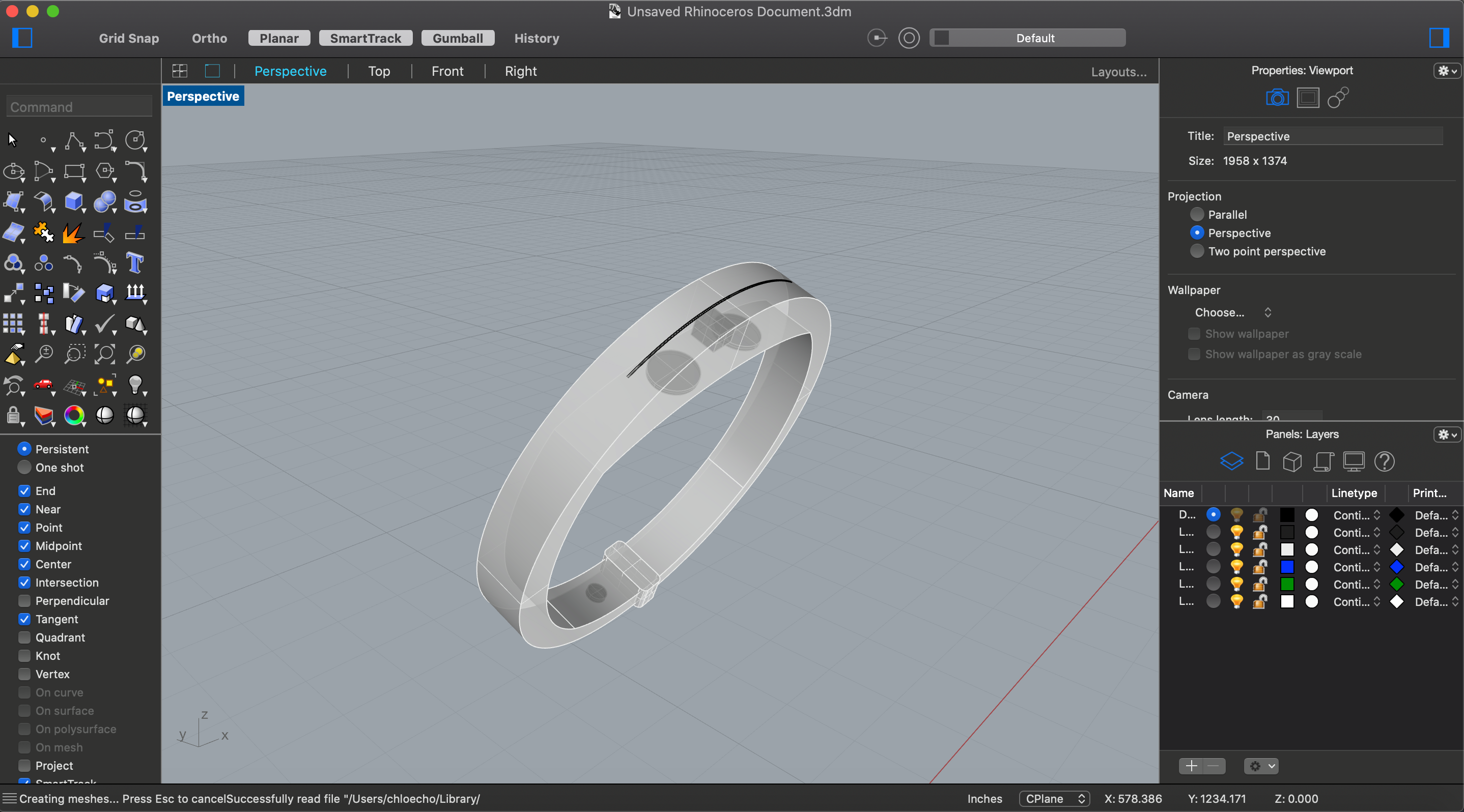
General difficulty making the model with exact dimensions. Vibration motor is at the bottom of the wrist since the skin is the thinnest and therefore most sensitive.
To solve the issue of orientation, Chloe put a gray dot in the bracelet to indicate that this is the faster frequency where the range begins. Diane would be able to know this intuitively through extended use over time.
Gray dot placed to indicate orientation
Works-like prototype
For building the technical part of the bracelet, Ivan’s main constraint came from the size of the bracelet, as normal electronics would be hard to fit inside. After talking with Zach, Ivan decided to use the attiny, rather than the regular Arduino uno (or even the Arduino mini), as it had the smallest form factor.
Motor doesn’t respond when the power is directly connected to the attiny. Required a transistor connected to the coin cell battery to solve the issue.
Using the attiny required some troubleshooting, however, as when it was directly connected to the vibration motor, the motor was not responding to the inputs. Suspecting that the attiny was unable to power the motor properly, Ivan tested out the attiny with an LED bulb that requires less power and found his speculation to be correct. In order to readjust from there on, he used a transistor to connect to the motor’s power from the cell battery, rather than connecting the motor’s power to the attiny.
Conclusion
The final crit gave us good insight into the strengths and weaknesses of our project. Most everyone that commented really enjoyed the simplicity and elegance of the design, and found it to be useful in a variety of contexts.
Comments from crit and our responses
“I like the sleek and compact design. However, how do you change the batteries out? Is there a door of some sort? Would it be possible to use rechargeable cells and implement wireless charging of some sort?”
Lots of concerns were raised about changing the batteries. In the final design, there would be an opening to change the batteries when necessary. I’m not sure if it would’ve been possible to make this device rechargeable, as I’m not sure what component would be used to make that. It brings up a good question of how the user knows when the thing is out of battery versus just malfunctioning. Maybe a battery indicator would’ve been a nice touch to include.
“Your device is interesting in the way that it allows you to customize frequencies. But considering that the origin of this idea was the fact that she focused on a song have you thought about including different grooves, like a swing beat, or a clave?”
This was an interesting suggestion. I think we could have gone in the direction where Diane gives us 5 theme songs that she typically has in her head and we translate them into beats… But this may require more processing power, making the bracelet less compact as we designed for. Moreover, having a simple metronome matched closer to her original intent of wanting to calm down through regular beats.
“I love the design of the first bracelet as well as the second, and Diane seems to really love this! I am still confused, is the vibration beat already programmed, and she is able to change the frequency?”
This comment was similar to one of the questions we received during the critique session, where one of the Osher students wasn’t sure how Diane would pick the range of frequency for the metronome. While we discussed with Diane that the beats shouldn’t be too fast, that was the extent of our conversation regarding the range. Perhaps there could have been another potentiometer that sets the minimum frequency…
“Nice! Diane obviously loves it–most important! I’m not a Fit Bit user, but assuming that a Fit Bit doesn’t have this functionality? Also could there be a music component, for when Diane would like to relax with other sounds and not just beats? I loved the first design with the different size dots. I also wonder if these could be good for musicians who need/use metronomes.”
From our research, FitBit doesn’t have the exact metronome functionality, but there is an existing metronome bracelet geared towards musicians. (https://www.youtube.com/watch?v=E_nLhiYdfuY) It has a very large interface and noticeable LED lights, mainly for DJs to know the beats when they are performing. Our project was meant to be surreptitious in Diane’s life, as Diane did not want something that catches someone’s attention. As for the other suggestion of having sounds, that would also go against Diane’s desire to make this device be invisible. (Even if this was somehow connected to her headphones, that would make this useless in her primary use case of working with other people.)
Overall reflection
As for the remote conditions of this project, we found ourselves having very distinct works, rather than cross collaborating as projects usually go. For instance, Elizabeth and Chloe worked on the design one after another, rather than with each other, as it was difficult to design a 3d model of something together remotely. This led to some significant design changes from one person to another, and while the design improved in the second phase, it would have been more fruitful if we had collaborated in-person. Moreover, at times when all of us wanted to discuss functionalities of the design, we ran into some frustrations where we had trouble understanding each other, as we didn’t have the usual whiteboard table to support our ideas.
As for working with Diane, we didn’t find the age gap to be too different from working with any other client, especially since Diane had a very non-age-specific problem that we had to address. (Being restless is something that is probably more common in younger people than older people, so we found it to be less about working with someone that is older, but more about someone who is full of energy.) Diane was very helpful in designing with us on the product, as she painted a very rich picture of what her life looks like, making it easy for us to make informed choices during the design phase. Diane likes having theme songs in her head. She works as a museum docent, but she can become pretty restless in public situations. She likes fashion and aesthetics, so she doesn’t want anything that screams a medical device… We connected these helpful dots early on to create the metronome, rather than some music playing device as typical “calming” products go, making our project unique but fitting for Diane’s lifestyle.
Overall, we think that we made the right choice in maintaining the simplicity of the bracelet. Throughout the process, there were some doubts within the group that the bracelet might be too simple for a final project, leading us to think of different features to add. However, all of those features were considered extraneous and taken out in the end, as a simple and clear design is much more useful than a complex and difficult one. This turned out to be a good decision, as every feedback we received mentioned how they appreciated the simplicity of the device. We hope to apply this learning in future projects – hopefully when remote conditions end, allowing us to actually see the project in real life.
Technical Details
Tinkercad
Again, it is important to note the presence of the breadboard is not a part of the final design. It was implemented to make clear the connections.
TinkerCad Breadboard Rendering
Link for Tinkercad: https://www.tinkercad.com/things/aW7kHITO1Dl
code
The code found in tinkercad can be found here:
//Wearable Metronome
//
//Takes an analoge input from the the pot membrane
//and turns the input into the frequency the vibrating
//motor would turn on. Note this code is for a ATTINY 85
//processor
//
// * pin mapping:
// *
// * pin | mode   | description
// * 3   | input  | potentiometer
// * 2   | output | npn transistor for vibrating motor
//

void setup()
{
  pinMode(3, INPUT);
  pinMode(2, OUTPUT);
}

void loop()
{
  unsigned int freq = map(analogRead(3), 0, 1000, 500, 5000);
  analogWrite(2, 255);
  delay(500); // Wait for 1000 millisecond(s)
  analogWrite(2, 0);
  delay(freq); // Wait for 1000 millisecond(s)
}
However, since the tinkercad version uses a normal potentiometer, whereas our final product needs to use a softpot membrane, which doesn’t store the input, we need to change our code a little bit. We added a storage variable to keep track of the selected state of the softpot membrane. This code hasn’t been tested due to the inability to get our hands on a softpot membrane due to the COVID-19 situation, so there could be errors with the mapping.
//Wearable Metronome
//
//Takes an analoge input from the the pot membrane
//and turns the input into the frequency the vibrating
//motor would turn on. Note this code is for a ATTINY 85
//processor
//
// * pin mapping:
// *
// * pin  |  mode   |  description
// * 3    |  input  |  softpot membrane
// * 2    |  output |  npn transistor for vibrating motor
//

int store;
unsigned int freq;

void setup()
{
  pinMode(3, INPUT);
  pinMode(2, OUTPUT);
}

void loop()
{
  if (analogRead(3) > 5){
    store = analogRead(3);
    freq = map(store, 0, 1000, 500, 5000);
  }
  analogWrite(2, 255);
  delay(500); // Wait for 1000 millisecond(s)
  analogWrite(2, 0);
  delay(freq); // Wait for 1000 millisecond(s)
}
Circuit schematic
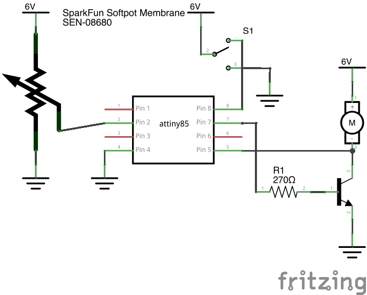
Circuit Diagram depicting final circuit with softpot membrane
Comments are closed.