
Images:
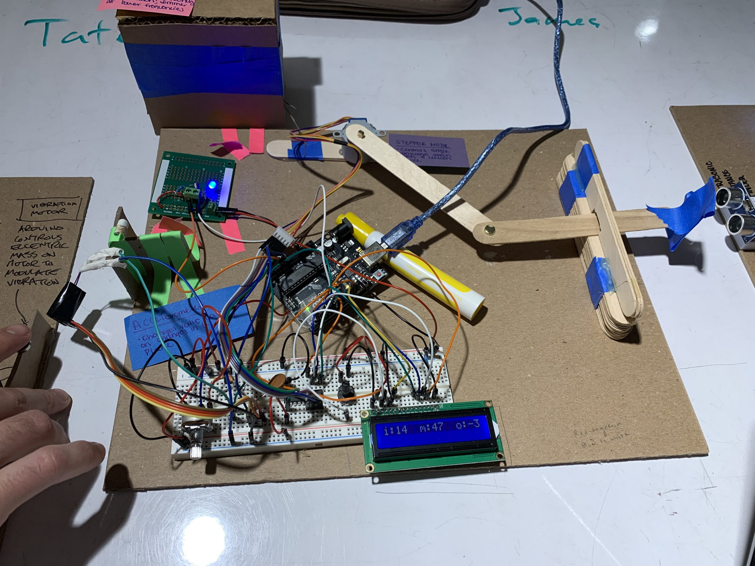
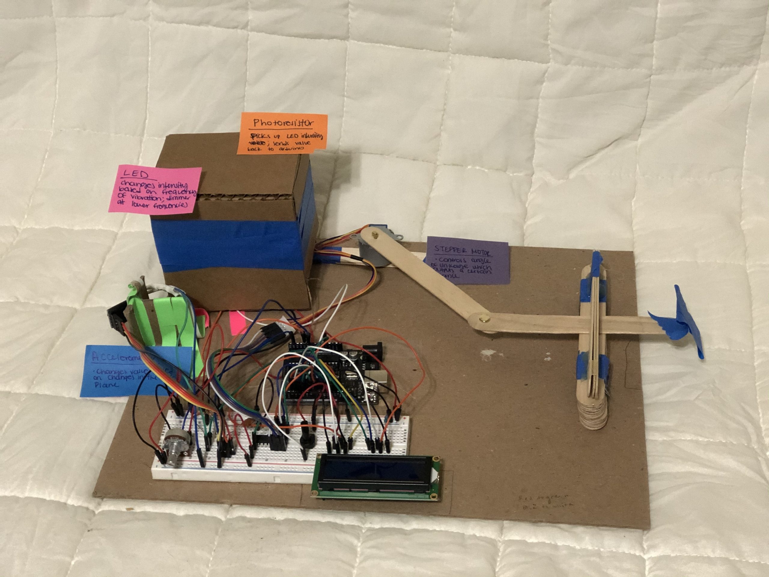
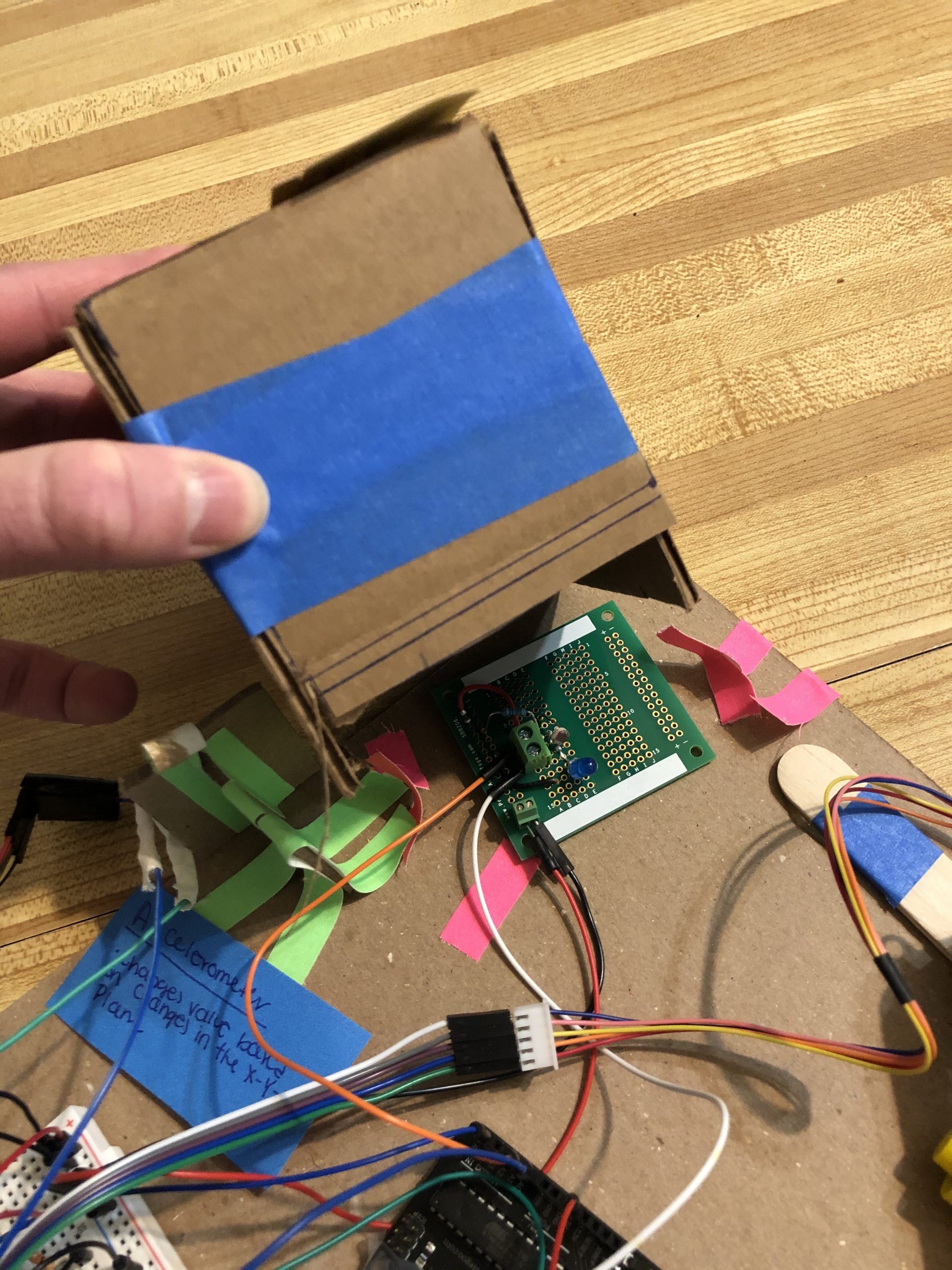
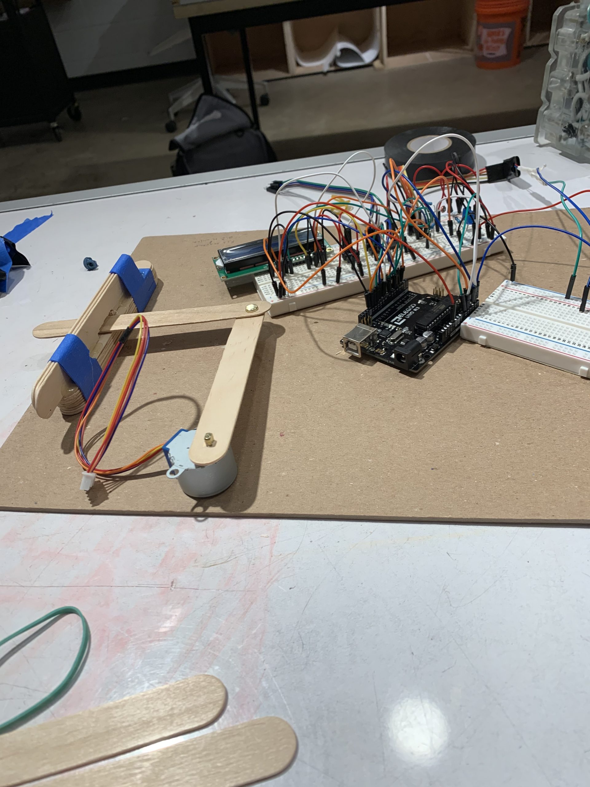
James’ final build
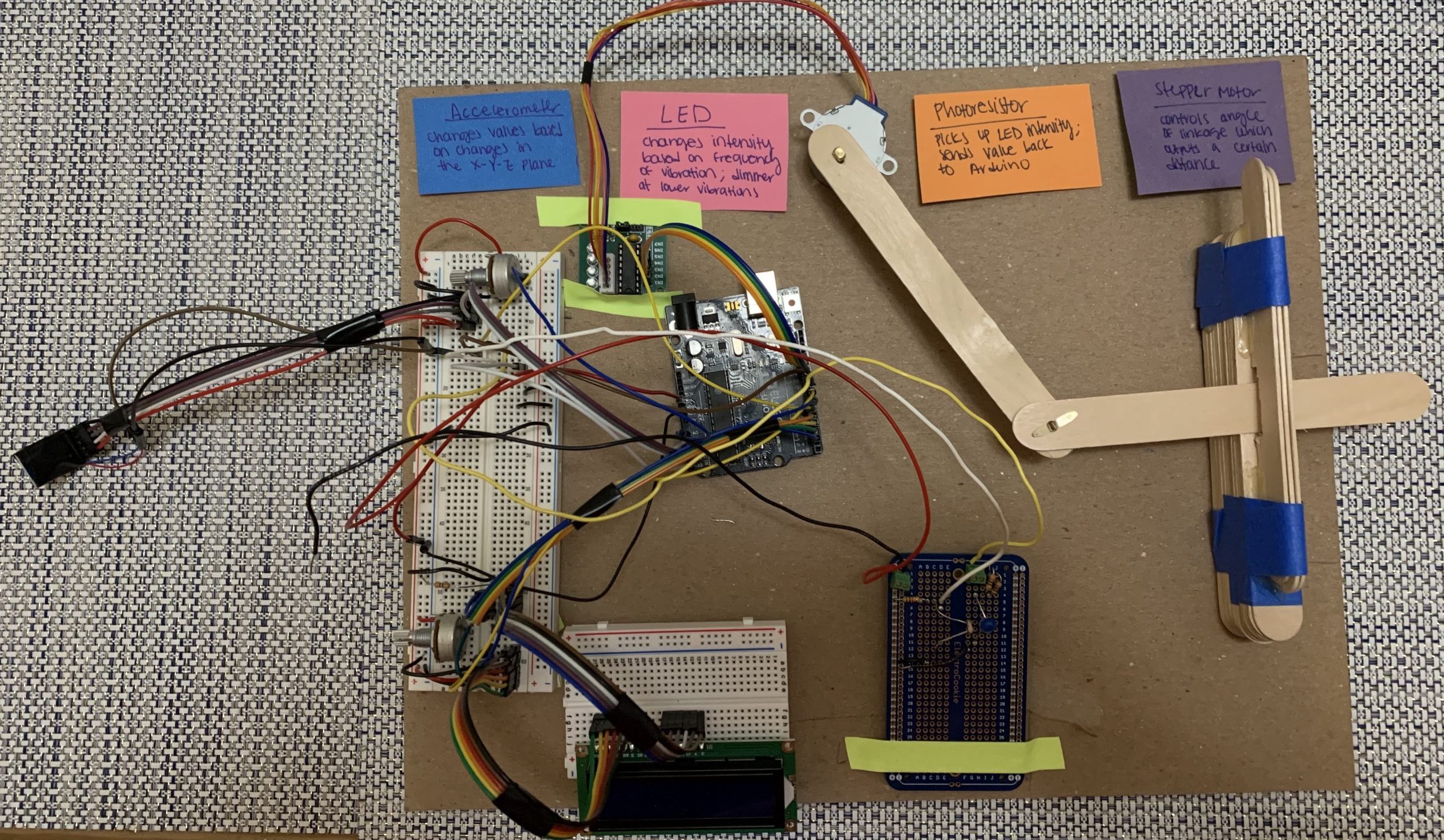
Amelia’s final build
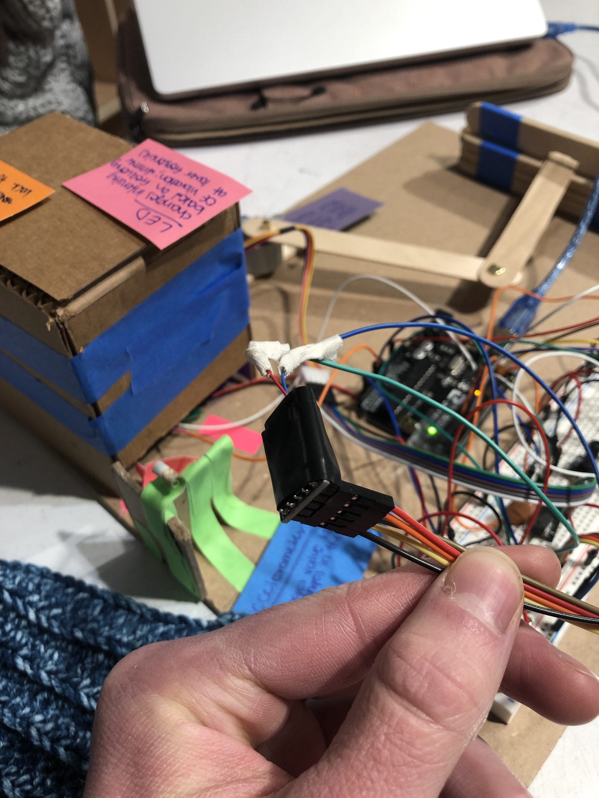
Taped connection between vibration motor and accelerometer for best transfer of signal
Cover for the light sensing part of transducer to get rid of noise from environment
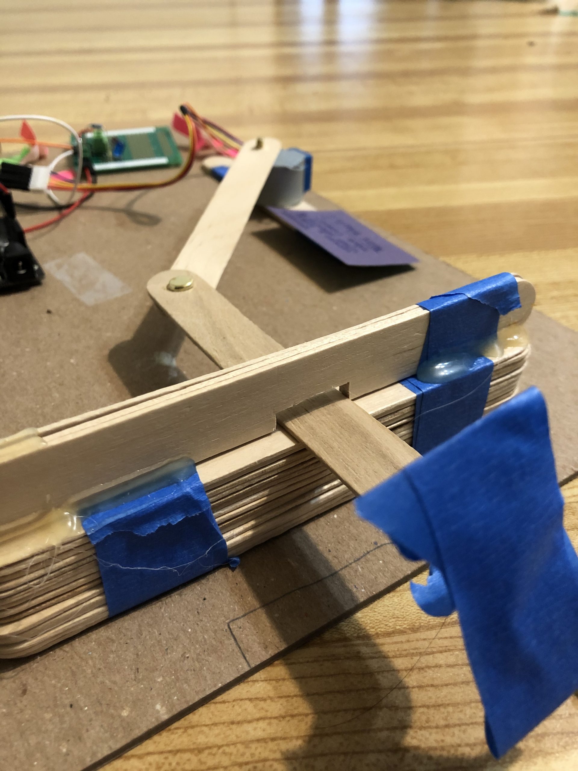
Slot restricting the motion of Popsicle stick to mostly linear movement to create a change in distance
Narrative:
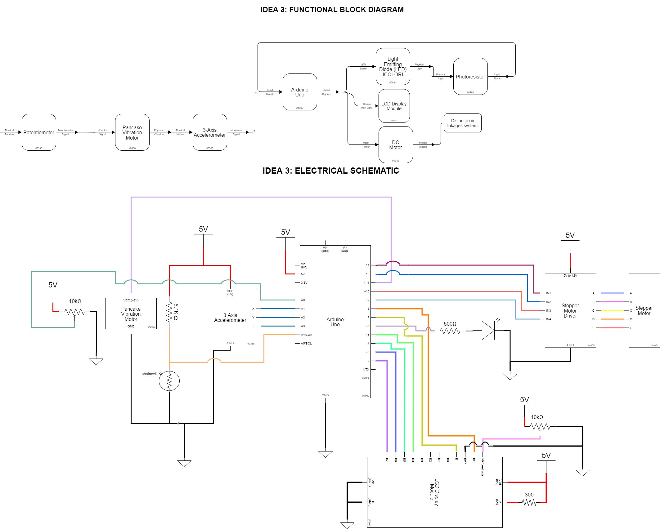
A vibrator is attached to a sensor which senses the rate of vibration. Based on this vibration, a light is turned on underneath a box. How much the vibrator vibrates determines how bright the light gets. So if the vibrator vibrates a lot, the light gets really bright, and if the vibrator does not vibrate a lot, the light does not get as bright. The brightness of the light is captured by another sensor which senses how bright the light is. The sensor then tells the computer how much to turn a motor to move a stick. So if the light is really bright, the motor is told to move the stick very far, and if the light is not as bright, the motor is told to move the stick not as far. The states of all of these inputs and outputs (i.e. the level of change) is fed to a display that shows how much each step has changed.
Progress images:
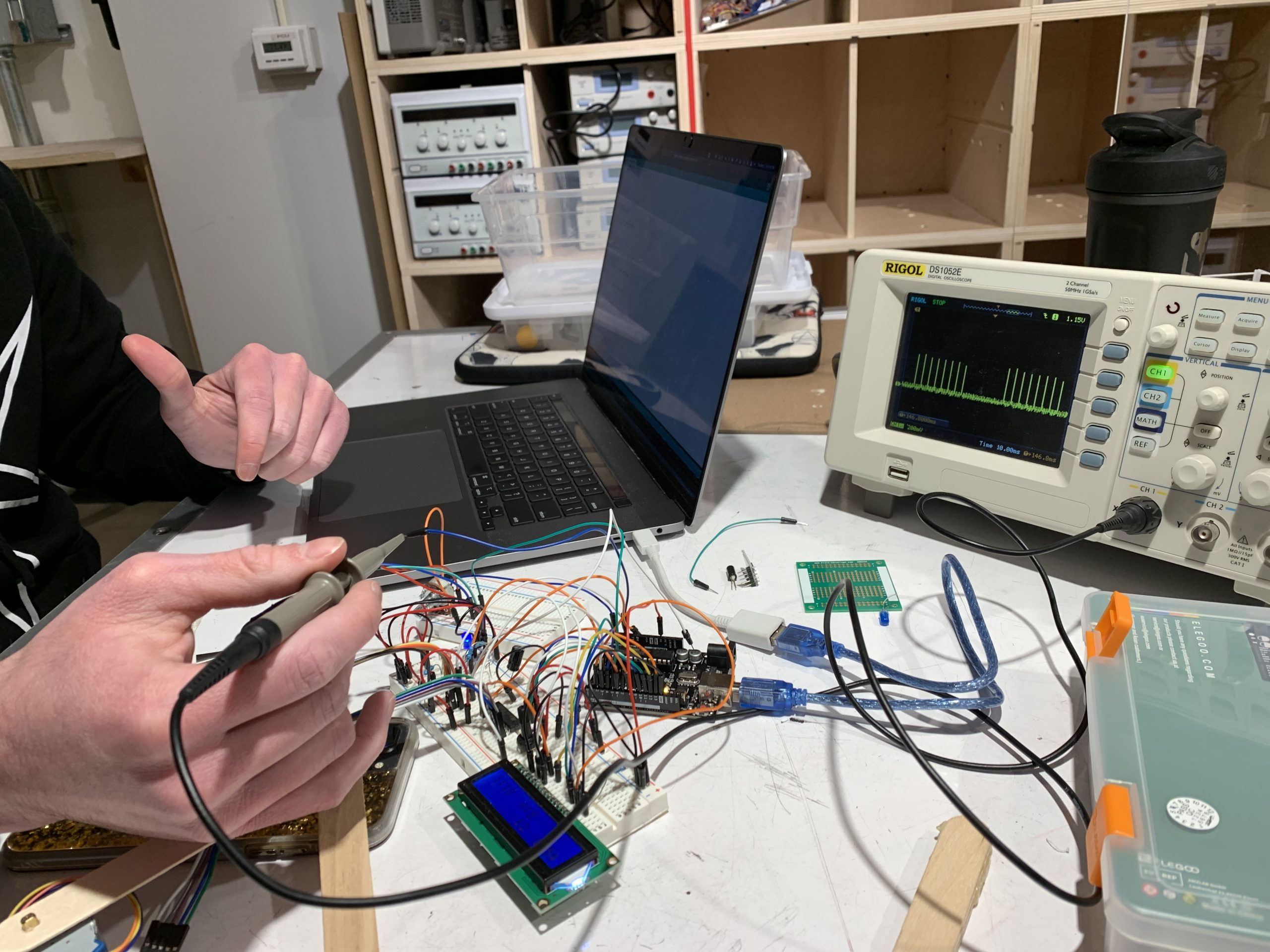
Diagnosing the noise in the analog input pins with an oscilloscope
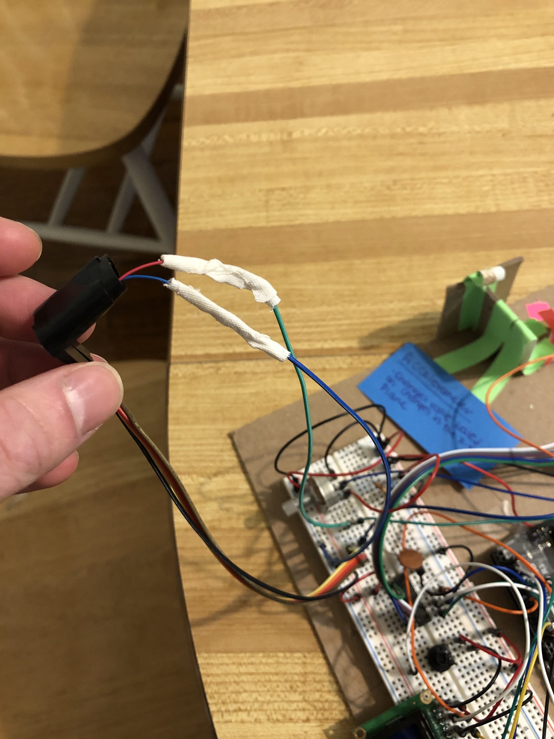
Vibration motor connected to two wires with male ends to make better and more maneuverable connection to bread board
One of the many ways we tried to sense vibration frequency. Here we are trying to measure the duty cycle of the PWM type input from the vibration motor.
Putting together the distance component for the first time to get the layout
Discussion:
Throughout the development process, the easiest part was definitely the planning stage. The stage where we brainstormed three different ideas and paid little attention towards the actual build. It was a time where we let our imaginations run wild and had little to debug since the projects weren’t fully implemented, only idealized. Once we finally got to the building and coding stage however, we found implementing past the planning phase is much harder. It involved having to build the circuit while making sure none of the wires had loose connections, building a connection between the vibration motor and Arduino which meant stripping two male- to-female wires as well as the vibration motor and securing them together with athletic tape (neither of us had electrical tape on standby), measuring the value of the accelerometer with a broken accelerometer (which we only later realized), soldering an LED and photoresistor, building a linkage system out of popsicle sticks, and figuring out the code to tie these pieces together. All of these steps came with their own frustrating challenges that allowed us to grown our knowledge of sensors and Arduino development
The most frustrating thing that we learned was that analog input pins on the Arduino can pick up a lot of noise from other parts of the board. In particular, adjacent analog input pins can read signals from each other almost as if they were connected. In our case, we thought the accelerometer was wired to the Arduino and we were reading a signal from it, but it turned out to not be connected to the Arduino at all. Despite this fact, we still read an analog input from that pin and when compared to the signal produced by the potentiometer, the signals matched exactly in how they changed with input into the potentiometer. Instead of reading the accelerometer data, we were actually reading ghost signals from the adjacent potentiometer input pin which was only solved by moving the accelerometer input pin to the opposite side of the analog input pin array.
We also learned the importance of data structures in signal processing, especially when performing arithmetic operations. While trying to write values to our stepper motor, we came into a problem where we couldn’t get our code to run for more than 1 loop. This was caused by the way in which we were storing the variables used to calculated step count. We chose to store the all our variables as type “int” by default which meant that it would round down to the nearest integer when it stored the step value. The some of the values we were setting as the used to calculate the number of steps, however, were on a scale of 0 to π which meant that they were frequently in between 0 and 1. Because these values were rounded down even if they were 0.9, this meant that we ended up with division by zero causing our program to break and only run once. Storing the variables used to calculate step number solved this problem.
Looking back now, there are several factors that would’ve changed the direction of the project completely. For instance, the first time we met to work on the project was the Sunday before the project was due because we thought it was plenty of time before the deadline. This was a mistake on our part and we should’ve been more proactive about meeting before Sunday (i.e. on Friday and Saturday). This would’ve given us more time to realize where we were going wrong and what we could’ve done to fix the problem. Another factor would’ve been a better sensor to detect the frequency of the vibration coming from the vibration motor. We noticed that the accelerometer was pretty noisy and we had trouble reading the sensor. Maybe these changes would have improved our project, or possibly caused new problems, but these are just a few we’ve chosen to reflect on.
Functional Block Diagram and Schematic
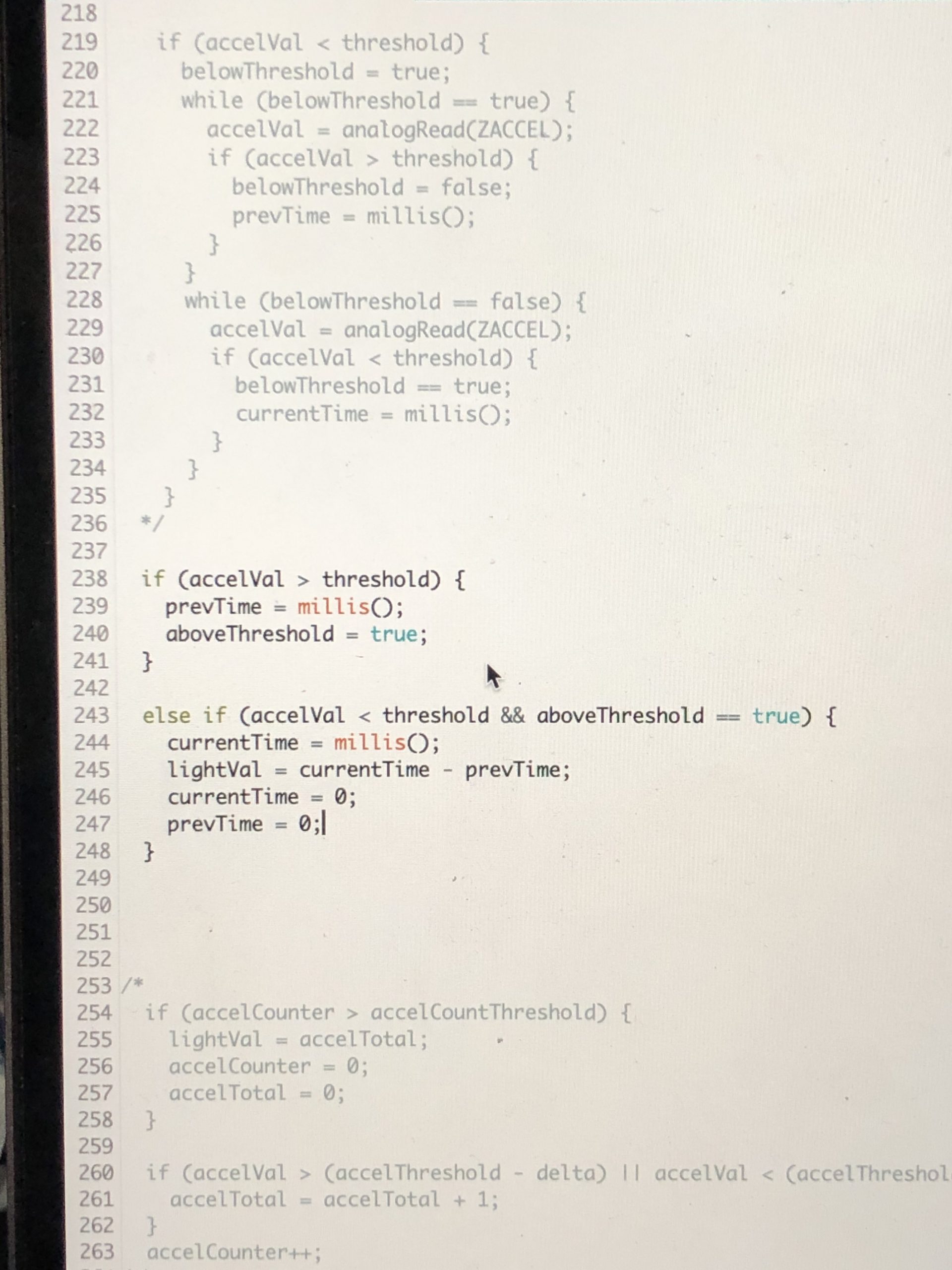
Code Submission
/*
   60-223, Project 1
   Amelia Lopez (aelopez)
   James Kyle (jkyle1)
   Time spent: 8 hours

   Description:
   Takes in a vibration input, transforms that analog input value
   into an LED brightness, which is then transformed into a distance
   controlled by the stepper motor. Vibration input is read through
   an accelerometer and LED intensity value is read through a photoresistor.

   Challenges:
   The stepper motor isn't responding to the photoresistor's value as
   we intended, so that half of the code is buggy. Since the vibration
   motor works on a pulse, this causes the light to blink fairly fast but
   it still dims/brightens as a result of the vibration motor speed.

   Next time:
   Definitely take more time to understand what went wrong between the
   photoresistor value and the stepper motor desired output. I think
   looking at the Arduino libraries is a good place to start with this
   because maybe someone else had the same problem and published their
   solution for open source use that we can cite and tweak to the specs
   of our project


   Collaboration and Sources:
   1) For the accelerometer readings (line 163-167), used code from
    https://tinyurl.com/Accelerometerlink
   2) For LCD display, used code from http://www.arduino.cc/en/Tutorial/LiquidCrystalHelloWorld
   3) For stepper motor, used code from https://tinyurl.com/StepperMotorLink

   Inputs: Potentiometer (which varies vibration motor rate)
   In-between: LED
   Output: Stepper motor, LCD display

  Pin mapping:

   Arduino pin | type   | description
   ------------|--------|-------------
   A0            input     potentiometer
   A1            input     X-pin Accelerometer
   A2            input     Y-pin Accelerometer
   A3            input     Z-pin Accelerometer
   A4            input     photoresistor
   13            output    Stepper Motor Driver IN1
   12            output    Stepper Motor Driver IN2
   ~11           output    Vibration motor
   ~10           output    Stepper Motor Driver IN3
   ~9            output    Stepper Motor Driver IN4
   8             output    LCD RS
   7             output    LCD E
   ~6            output    LED
   ~5            output    LCD D4
   4             output    LCD D5
   ~3            output    LCD D6
   2             output    LCD D7

   (digital PWM~)

     LCD circuit:
   LCD RS pin to digital pin 8
   LCD Enable pin to digital pin 7
   LCD D4 pin to digital pin 5
   LCD D5 pin to digital pin 4
   LCD D6 pin to digital pin 3
   LCD D7 pin to digital pin 2
   LCD R/W pin to ground
   LCD VSS pin to ground
   LCD VCC pin to 5V
   10K resistor:
   ends to +5V and ground
   wiper to LCD VO pin (pin 3)
*/

#include <Stepper.h>
#include <LiquidCrystal.h>


//DECLARING ARDUINO PINS
const int POTENT = A0;
const int ACCE_X = A1;
const int ACCE_Y = A2;
const int ACCE_Z = A3;
const int PHOTORES = A4;
const int STEP_IN1 = 13;
const int STEP_IN2 = 12;
const int VIBRATION_MOTOR = 11;
const int STEP_IN3 = 10;
const int STEP_IN4 = 9;
const int LCD_RS = 8;
const int LCD_E = 7;
const int LED_PIN = 6;
const int LCD_D4 = 5;
const int LCD_D5 = 4;
const int LCD_D6 = 3;
const int LCD_D7 = 2;

//DECLARING INTS FOR ACCELOREMETER AND LED
int accel_xVal = 0;
int lightVal = 0;


//DECLARING MISC. CONSTANTS USEFUL TO STEPPER MOTOR
const int maxAnalogValue = 1023;
const int stepsPerRevolution = 64; //fits the specification of our motor
const int motorSpeed = 20;
float currentDistance = distOfString / 2; //PRECONDITION: OBJECT HAS TO BE HALFWAY
int targetDistance;
float steps;
bool stepMotor = false;

//DECLARING INTS FOR LCD WAITING TIMES
const int WAIT_TIME = 300;
unsigned long timeVariable = 0;

// initialize the library by associating any needed LCD interface pin
// with the Arduino pin number it is connected to
LiquidCrystal lcd(LCD_RS, LCD_E, LCD_D4, LCD_D5, LCD_D6, LCD_D7);


Stepper myStepper(stepsPerRevolution, STEP_IN1, STEP_IN2, STEP_IN3, STEP_IN4);

void setup() {

  //INPUT PINS
  pinMode(POTENT, INPUT);
  pinMode(VIBRATION_MOTOR, OUTPUT);
  pinMode(ACCE_X, INPUT);
  pinMode(ACCE_Y, INPUT);
  pinMode(ACCE_Z, INPUT);
  pinMode(PHOTORES, INPUT);

  //OUTPUT PINS
  pinMode(LED_PIN, OUTPUT);
  pinMode(VIBRATION_MOTOR, OUTPUT);

  //MOTOR functions
  myStepper.setSpeed(motorSpeed);

  // set up the LCD's number of columns and rows:
  lcd.begin(16, 2);

  //print constant letters on screen
  lcd.print("i:");
  lcd.setCursor(6, 0);
  lcd.print("m:");
  lcd.setCursor(8, 1);
  lcd.print("0");
  lcd.setCursor(12, 1);
  lcd.print("o:");
}

void loop() {

  //READING POTENTIOMETER VALUE
  //POTENTIOMETER VALUE DETERMINES VIBRATION MOTOR RATE
  int potentValue = analogRead(POTENT); // 0 <= potentValue <= 1023
  int vibrationStrength = map(potentValue, 0, 1023, 0, 153);  // 0 <= vibrationStrength <= 155
  analogWrite(VIBRATION_MOTOR, vibrationStrength); //using PWM
  int xVal = analogRead(ACCE_X);

  //ACCELEROMETER MEASURES VIBRATION MOTOR RATE (x-axis)
  //RATE MEASURED IS USED TO LIGHT UP AN LED A CERTAIN INTENSITY
  int oldX = accel_xVal;
  accel_xVal = analogRead(ACCE_X);
  int dif = abs(oldX - accel_xVal);
  int lightVal = map(dif, 0, 520, 0, 255);
  analogWrite(LED_PIN, lightVal);


  //PHOTORESISTOR TAKES IN LED INTENSITY VALUE
  //PHOTORESISTOR VALUE USED TO CHANGE STEPPER MOTOR
  int photoValue = analogRead(PHOTORES); // 0 <= potentValue <= 1023
  int lowbound = 700; //bright light
  int highbound = 990; //no light
  //int stepVal = map(photoValue, lowbound, highbound,

  targetDistance = map(photoValue, 850, 1000, 0, 60);

  //Convert photoresistor value into desired distance into rotations for stepper motor
  if (targetDistance != currentDistance) {
    steps = (targetDistance - currentDistance) * stepsPerRevolution / 360;
    currentDistance = targetDistance;
    stepMotor = true;
  }

  //Setting step stepper motor to desired distance
  if (stepMotor == true) {
    myStepper.step(steps);
    delay(500); //Wait 0.5s for motor to finish moving
    stepMotor = false;
  }

  //UPDATING VALUES ON LCD
  if (millis() - timeVariable > WAIT_TIME) {
    //updating input sensor value
    lcd.setCursor(2, 0);
    lcd.print(map(xVal, 0, 525, 0, 99));

    //updating middle step actuator
    lcd.setCursor(8, 0);
    lcd.print(map(lightVal, 0, 255, 0, 99));

    //updating middle step sensor value
    lcd.setCursor(8, 1);
    lcd.print(map(photoValue, lowbound, highbound, 0, 99));

    //updating output actuator value
    lcd.setCursor(14, 1);
    lcd.print(map(steps, 0, currentDistance, 0, 99));
    delay(200);

    timeVariable = millis();
  }

}