
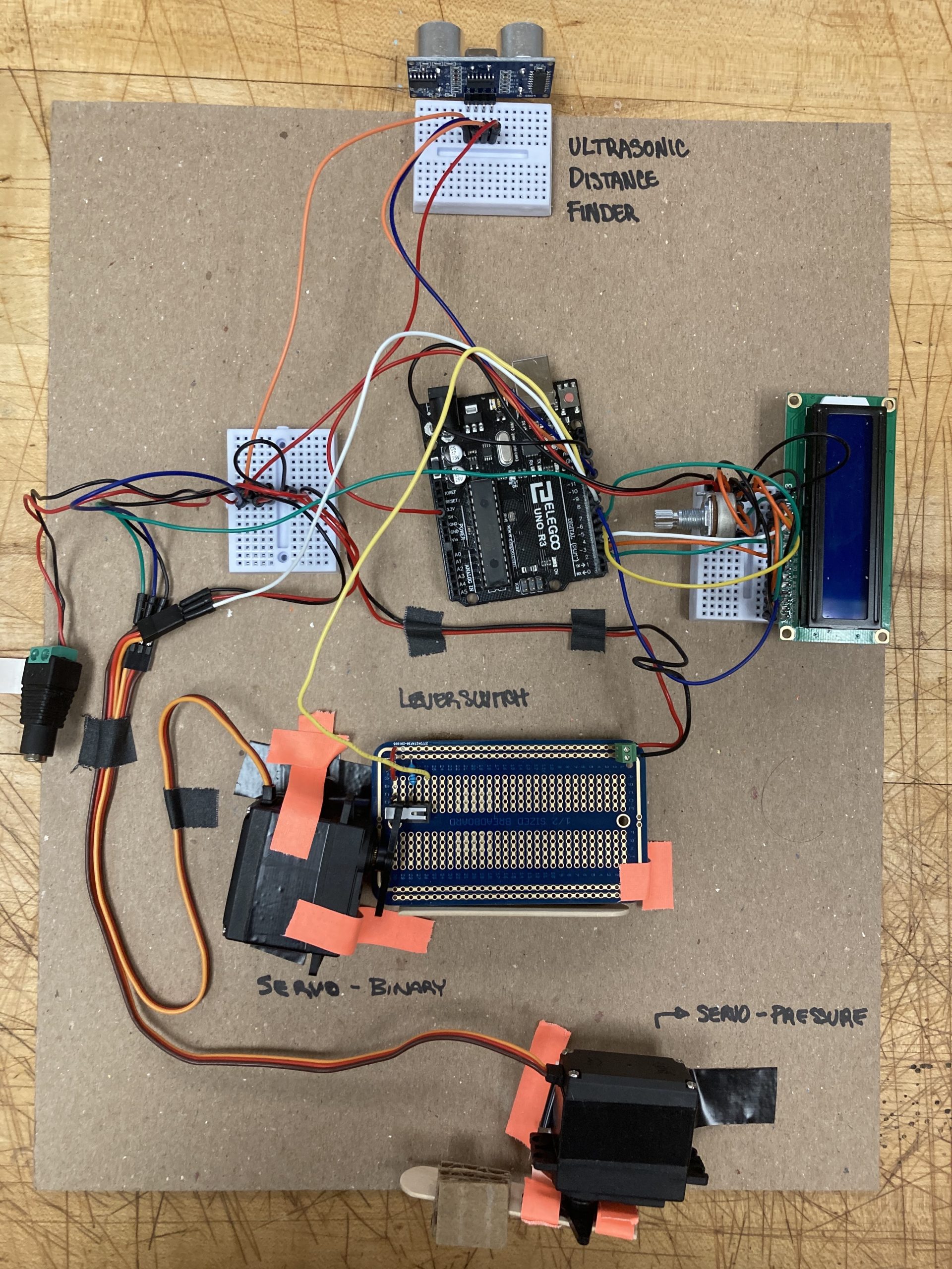
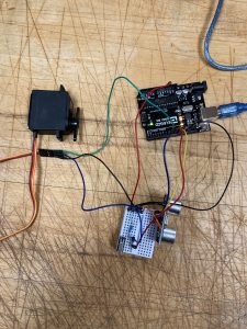
Distance to pressure double transducer.
Double Transducer IRL:
Daniel Zhu:
Sunjana:
TinkerCAD:
Final Project Images:
Daniel Zhu:
Distance to Pressure Double Transducer – Daniel Zhu
Sunjana:
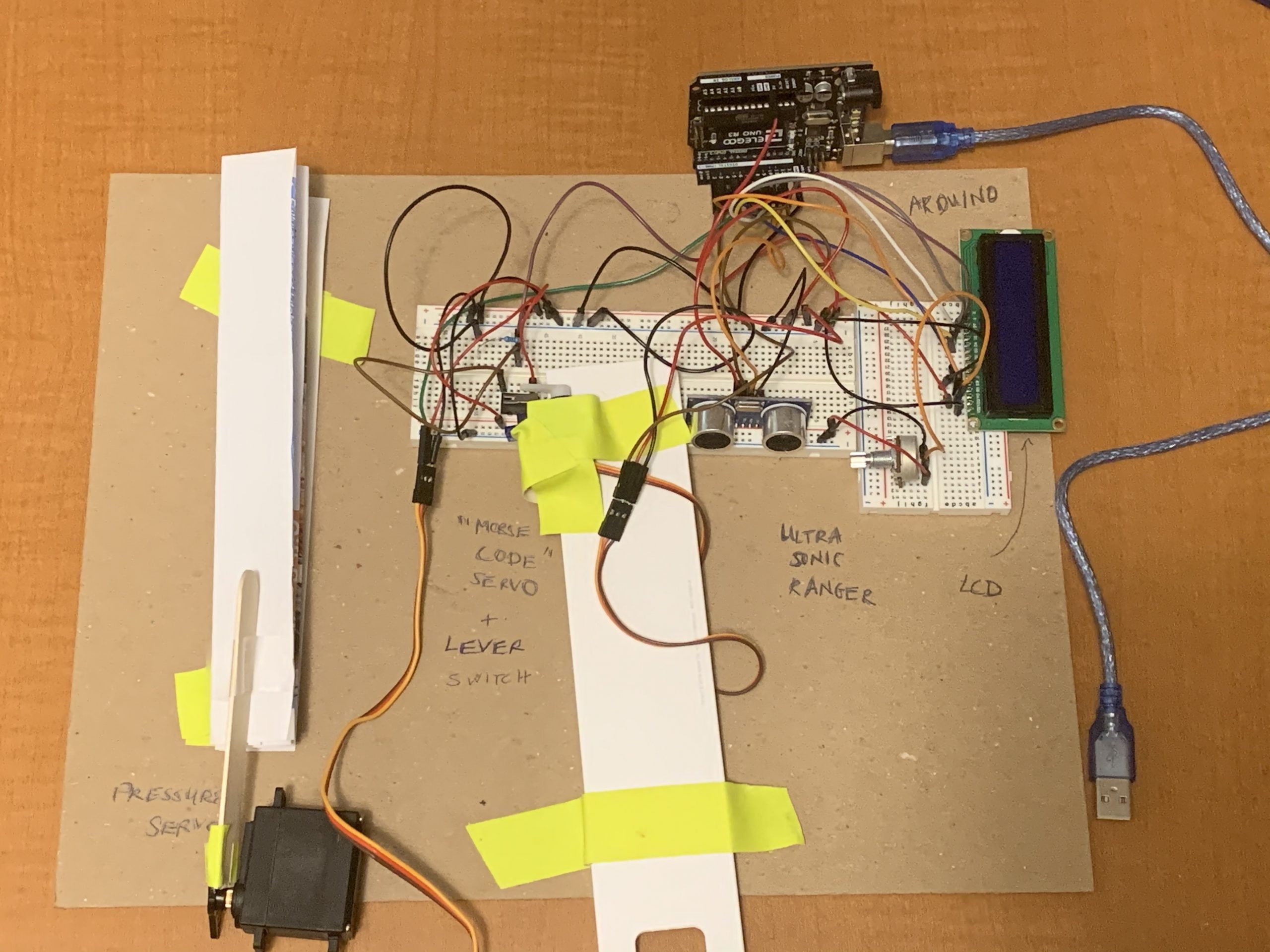
Close Up Images
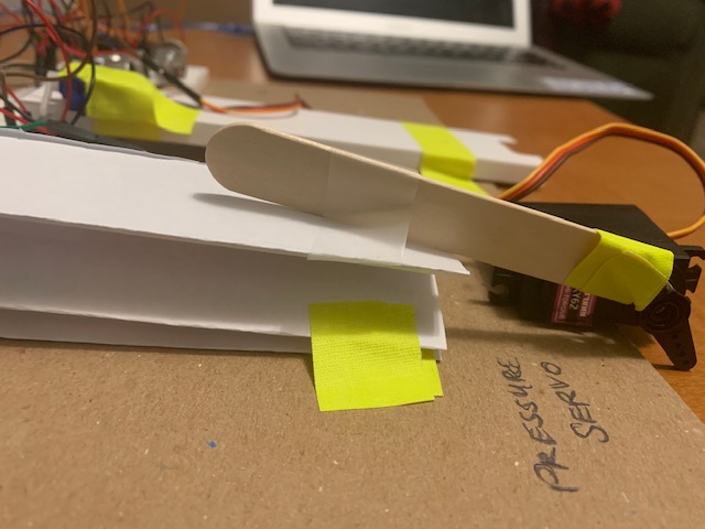
Close up of the method servo used to apply pressure to the paper
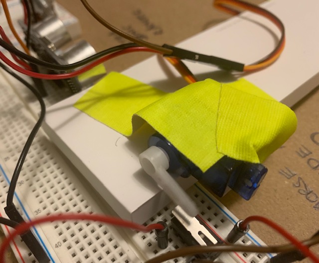
Close up of servo in position to press the lever switch intermittently when its shaft is turned programmatically
Simple Narrative Description:
As the distance between the Ultrasonic Distance Sensor and an object decreases, the rate at which a servo motor presses a lever switch increases. As the lever switch registers a faster and faster rate of being triggered, a second servo motor presses a stack of cardboard more closely to the table, applying more pressure. Conversely, as the distance between the Ultrasonic Distance Sensor and an object increases, the rate at which a servo motor presses a lever switch decreases. As the lever switch registers slower rate of being triggered, a second servo motor presses a stack of cardboard less closely to the table, relieving pressure.
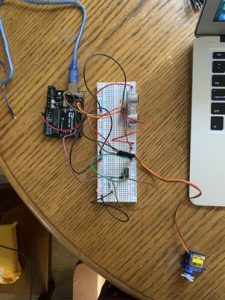
Progress Images:
Daniel Zhu:
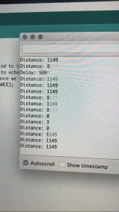
Noise in Ultrasonic Distance sensor data.
Sunjana:
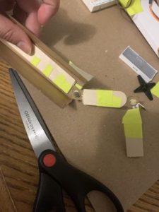
Converting rotational motion into pressure
Unsoldered prototype
Discussion:
This project introduced numerous physical, coding, and conceptual difficulties. Conceptually, it was difficult for us to come up with an idea to convert distance into pressure: while we had spent a lot of time working with light as a medium (LEDs) and movement, we hadn’t ever worked with any electrical components that had a specific function of exerting pressure. After speaking with the professor, we learned that in order to exert pressure, we could take inspiration from a crank that used a circular turning motion to push and pull an object. We then decided upon the idea of our second transducer outputting an angle change for a motor so it could turn like a crank and push and pull an object we created. The object in turn would apply pressure to a piece of paper as it was being pushed.
Physically, our challenge lay in orienting the different components of the machine (i.e. the servos and the button) so that they would form a chain reaction (i.e. a servo pressing a button intermittently, causing the other servo to intermittently apply pressure to a piece of paper). It took some trial and error to figure out which button was most responsive to the servo’s touch, as well as whether a servo or stepper motor was better suited to our task. It became too technically difficult for us to implement the crank with the stepper motor providing the circular turning motion, like we had originally intended, so we ended up going with the servo. In the future, we would want to be able to utilize the stepper motor as it would allow for more creativity in our output, since it turns 360 degrees.
Coding-wise, our challenge lay in figuring out the relationship between the first servo, the button, and the second servo, and how to pass information through each of these components. Specifically, we had to figure out how to convert the digital intermittent pressing of the button into an analog angle for the second servo. This also took a lot of debugging and trial and error, as we didn’t immediately know which angles of the servo were most optimal for pressing on the paper, and we didn’t know how we could change the angles such that the servo would be intermittently pressing down and intermittently going back up based on the button-pressing speed of the first servo.
Even though this project was extremely difficult, since we were relative Arduino beginners, we were able to go far out of our comfort zone and learn to put together various moving parts, as well as how to convert an analog signal to a digital signal and back to an analog signal.
Diagrams:
Block Diagram:
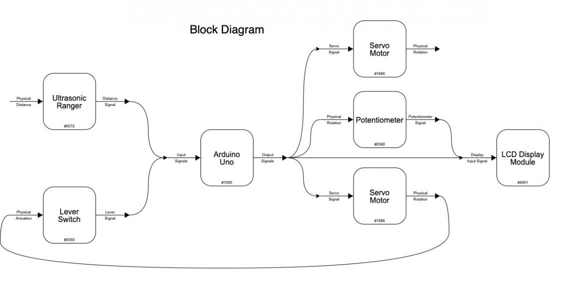
Block Diagram
Schematic Diagram:

Schematic Diagram
Code:
/*
   60-223, Project 1: Double Transducer
   Daniel Zhu (dszhu)
   time spent: 6+ hrs

   Collaboration and sources:
   1) Code for LCD taken from the course website.
   2) Code for Servo Motor take from course website.

   Challenge(s): A faulty barrel jack charger as well as
   noise in the LCD Display due to it being connected to
   a power source shared by servo motors caused it to display
   egyption hieroglyphics for several hours.

   Description: As the distance between the Ultrasonic Distance Sensor
   and an object decreases, the rate at which a servo motor presses a
   lever switch increases. As the lever switch registers a faster and
   faster rate of being triggered, a second servo motor presses a stack
   of cardboard more closely to the table, applying more pressure.

   Pin mapping:

   Arduino pin | type   | description
   ------------|--------|-------------
   2             output    LCD Display Coding Pin
   3             output    LCD Display Coding Pin
   4             output    LCD Display Coding Pin
   5             output    LCD Display Coding Pin
   6             output    LCD Display E
   7             input     LCD Display RS
   8             output    Output Servo Motor (Pressure)
   9             output    Middle Servo Motor (Morse)
   10            input     Lever Switch Input
   11            output    TRIGGER_PIN - Ultrasonic Distance Sensor
*/

#include <Servo.h> //Servo Library
#include <NewPing.h> //Ultrasonic Distance Finder Library
#include <LiquidCrystal.h> //LCD Library
#include <Wire.h> //LCD Library

//Ultrasonic Distance Sensor Pins
const int TRIGGER_PIN = 12;  // Arduino pin tied to trigger pin on the ultrasonic sensor.
const int ECHO_PIN = 11;  // Arduino pin tied to echo pin on the ultrasonic sensor.
const int MAX_DISTANCE = 200; // Maximum distance we want to ping for (in centimeters). Maximum sensor distance is rated at 400-500cm.
NewPing sonar(TRIGGER_PIN, ECHO_PIN, MAX_DISTANCE); //Createing a new Sonar object for use.

const int SDELAY = 50; // Minimum amount of delay between sonar pings
long sTimeSince = 0; // Time since last sonar ping
int dist = sonar.ping_cm(); // Keeps track of object distance from sensor

//Servo Motor Pins
const int BTN = 10; // Lever Switch
const int SERVO_IN = 9; // Middle Servo
const int SERVO_OUT = 8; // Output Servo
Servo Morse;
Servo Pressure;

long mTimeSince = 0; // Time since Middle Servo Triggered
bool mSwitch = false; // Keeps track of whether the servo is in the motion of pressing or returning

long pTimeSince = 0; // Time since Output Servo Triggered
int prsRate = 0; // Lever Switch input press rate

//LCD Display
const int rs = 7, en = 6, d4 = 2, d5 = 3, d6 = 4, d7 = 5;
LiquidCrystal lcd(rs, en, d4, d5, d6, d7);

long lTimeSince = 0; //Time Since LCD Display was last updated
const int lcdDelay = 250; // Minimum time between LCD updates

void setup() {
  pinMode(BTN, INPUT);
  Morse.attach(SERVO_IN);
  Pressure.attach(SERVO_OUT);
  Serial.begin(115200);
  lcd.begin(16, 2);
}

void loop() {

  if (millis() - sTimeSince > SDELAY) { // Triggering the Ultrasonic Sensor + Finding the Distance
    dist = sonar.ping_cm();
    sTimeSince = millis();
  }

  int pause = map(dist, 0, 50, 500, 1000); // Converts distance into how long the middle servo pauses between presses

  if (int(millis() - mTimeSince) > pause) { //pressing the middle servo motor
    if (mSwitch == false) { // Pressing the Lever Switch
      Morse.write(40);
      mSwitch = true;
    }
    else { // Unpressing the Lever Switch
      Morse.write(45);
      mSwitch = false;
    }

    prsRate -= 10; // Automatically Subtracting from the Pressrate of the Lever Switch
    Serial.print("Delay: ");
    Serial.println(pause);
    mTimeSince = millis();
  }

  if (digitalRead(BTN) == 1) { // Detecting LEvel Switch Input
    prsRate += 20;
  }

  if (prsRate > 100) { // Capping the pressrate before its conversion to angle to prevent servo failure
    prsRate = 100;
  }
  if (prsRate < 0) {
    prsRate = 0;
  }

  int angle = map(prsRate, 0, 100, 30, 20); // Converting the Pressrate of the Lever Switch to an Angle
  if (millis() - pTimeSince > 500) {
    Pressure.write(angle); // Moving the output motor to that angle
  }

  if (int(millis() - lTimeSince) > lcdDelay) { // LCD Display delay

    // Converting Middle values into 0-99 range for LCD
    int input = map(dist, 0, 50, 0, 99);
    int middleA = map(pause, 500, 1000, 0, 99);
    int middleS = map(prsRate, 0, 100, 0, 99);
    int output = map(angle, 20, 30, 0, 99);

    lcd.setCursor(0, 0);
    lcd.print((String)"i:" + input + " m:" + middleA);
    lcd.setCursor(8, 2);
    lcd.print((String)middleS + " o:" + output);

    lTimeSince = millis();
  }
}