Team Members: Kevin Bender, Nicole Yu
Tinkercad:
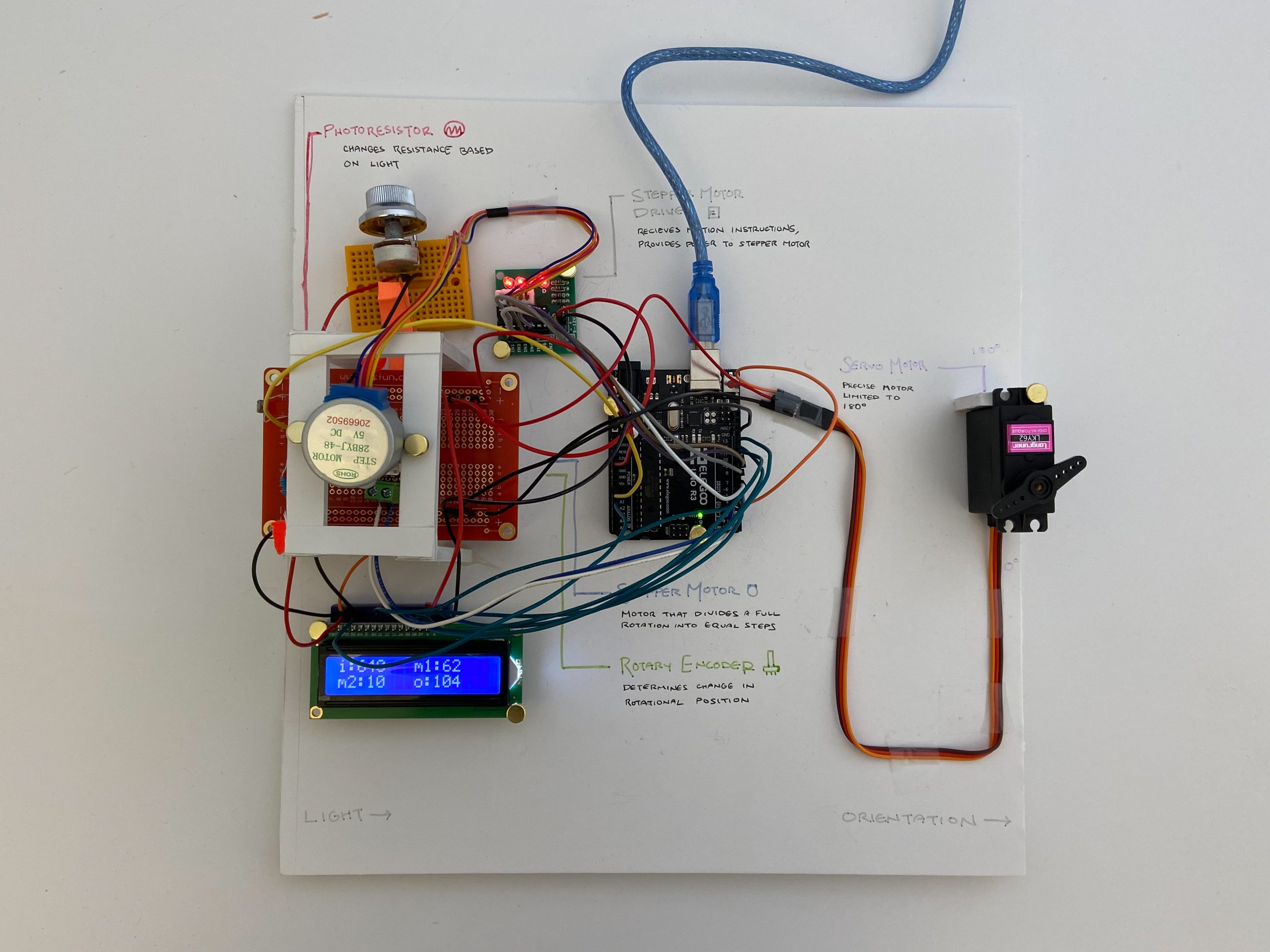
* the potentiometer on the left is representative of the rotary encoder. The DC motor and driver are representative of the stepper motor and driver
Overall:
Nicole’s final double transducer
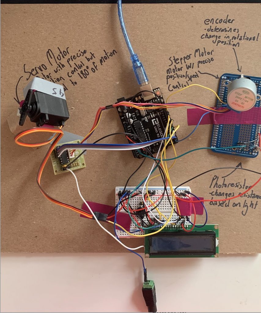
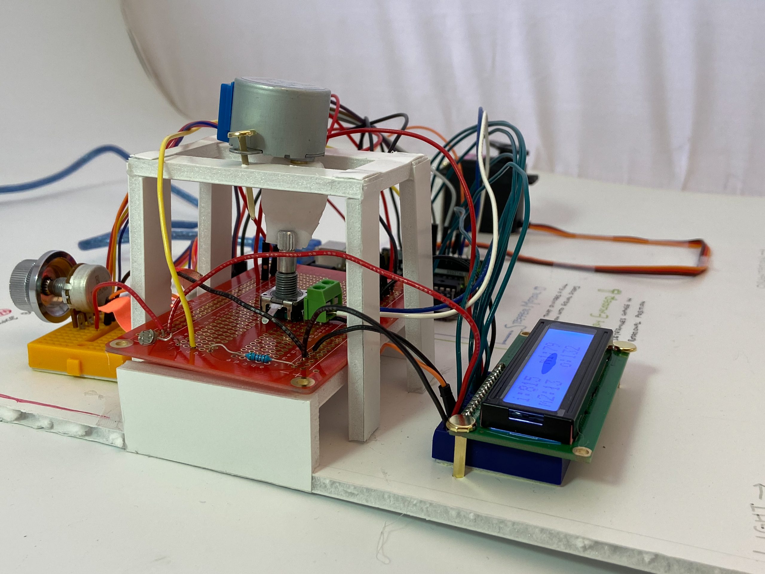
Kevin’s Final Double Transducer
Detail Photos:
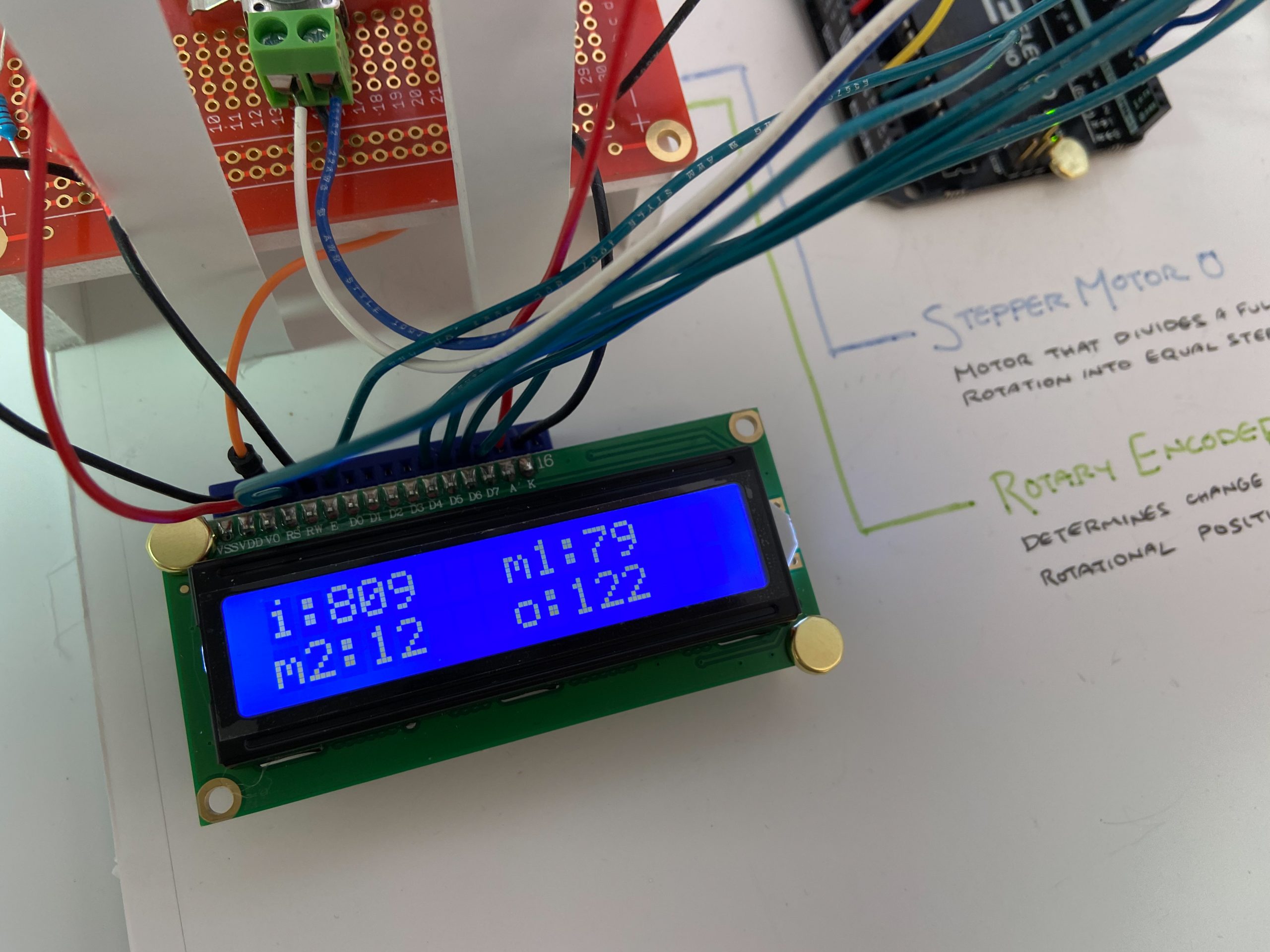
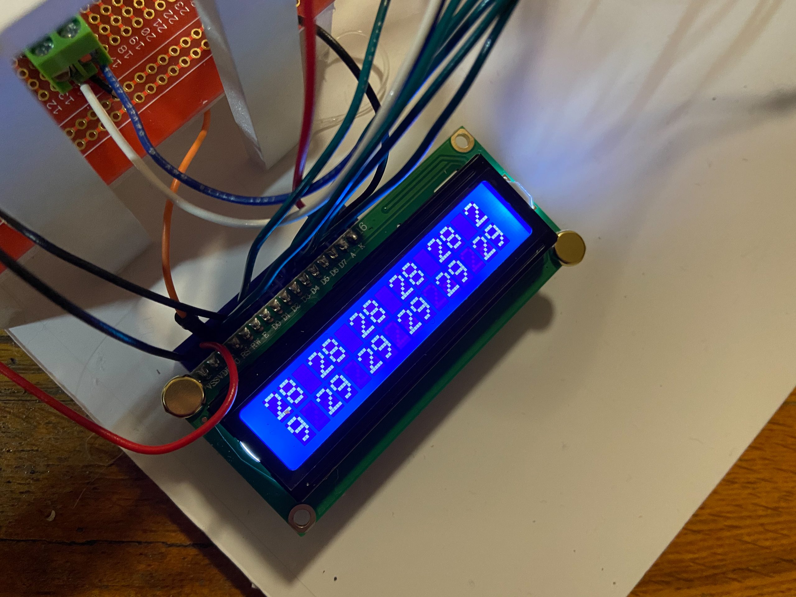
LCD input/output values
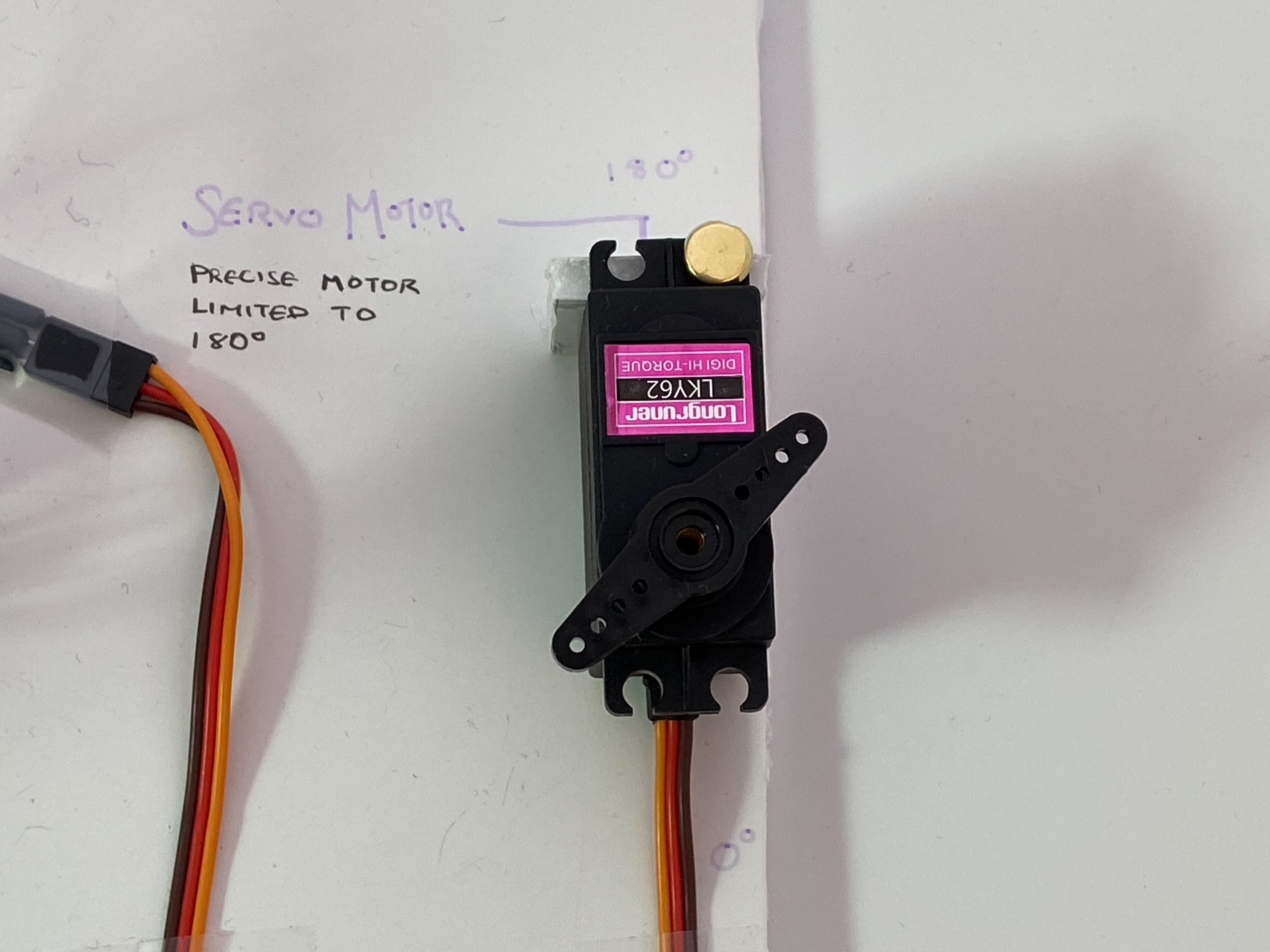
Servo motor “dial” (from 0º – 180º)
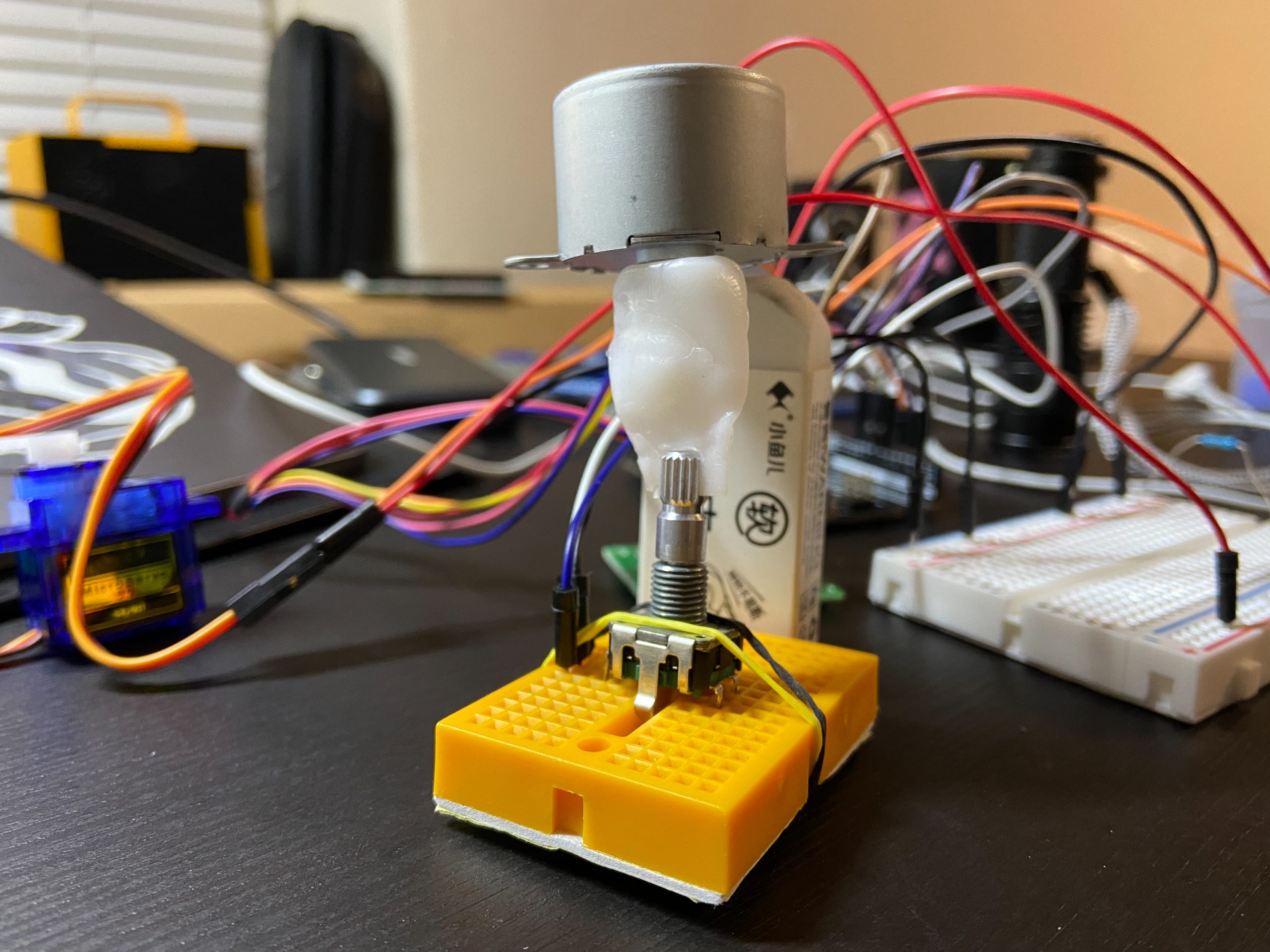
Close up of the connection between the stepper motor and rotary encoder
Final protoboard wiring
Brief Movies:
Description:
This device detects the amount of light through a photoresistor, and sends that signal to the stepper motor driver and stepper motor, which turns the rotary encoder at a certain speed. The rotary encoder determines how far it was rotated, and sends that data to the servo motor, which based on the data, turns to a certain angle (orientation).
Progress Images:
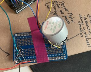
Figuring out the connection between the stepper motor and rotary encoder [Nicole]
An LCD that needs to be debugged [Nicole]
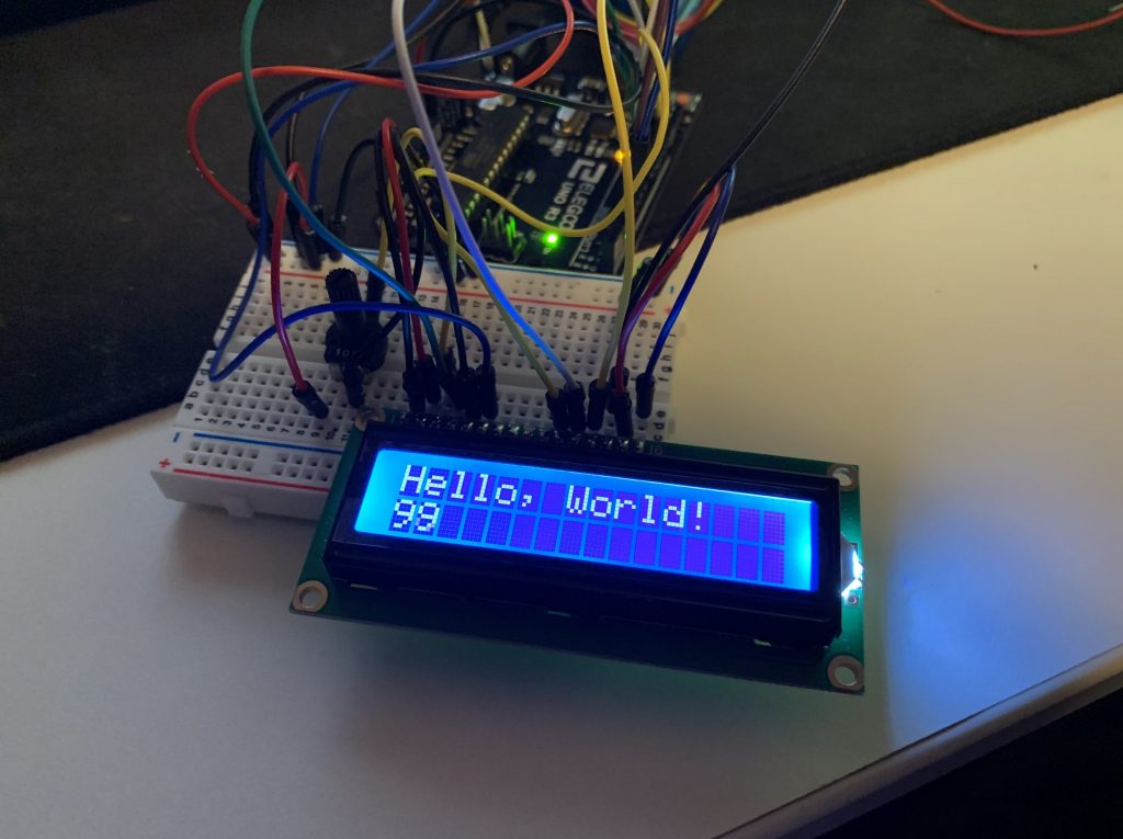
LCD setup with “Hello World” starter code from library [Kevin]
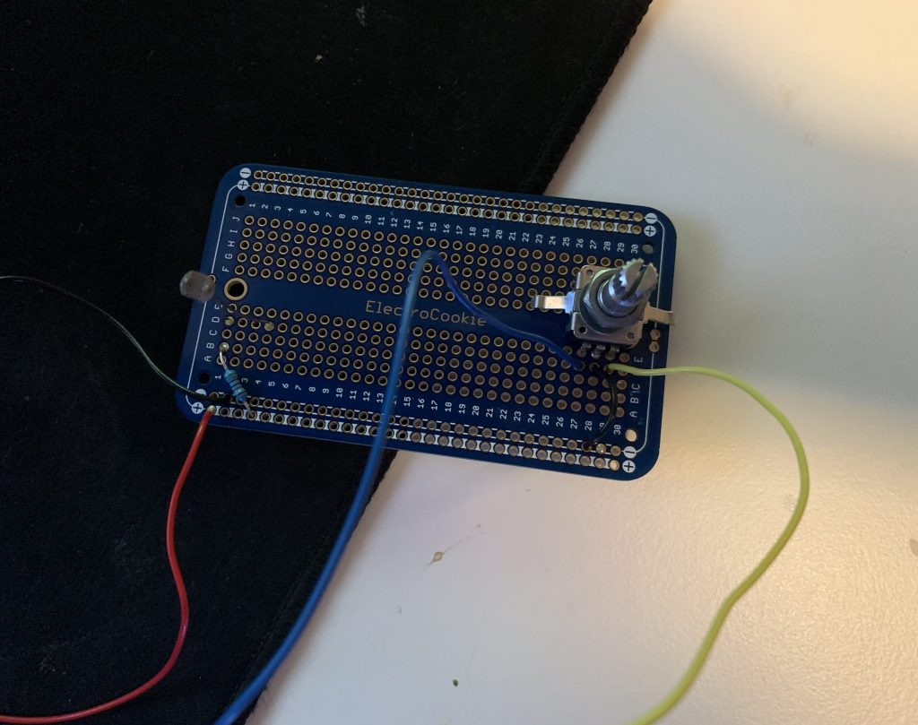
In-progress picture of soldering the photoresistor and encoder circuits onto a protoboard [Kevin]
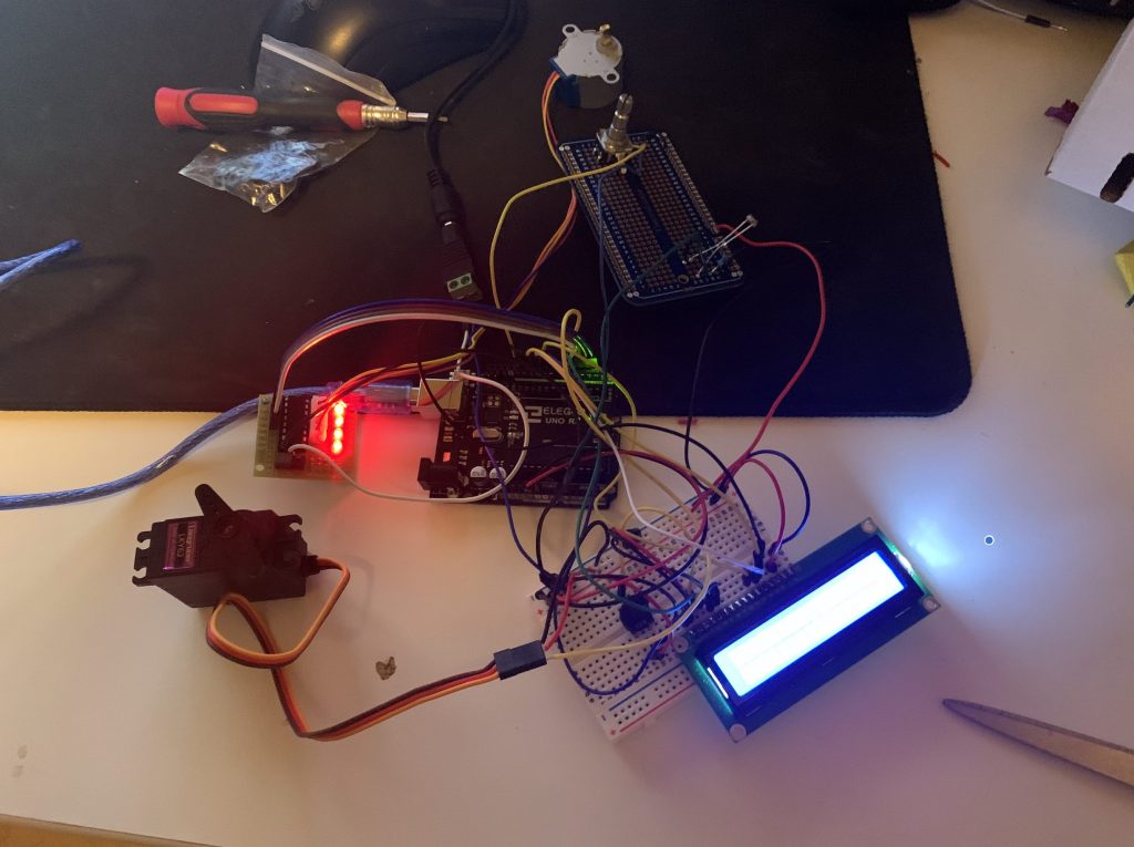
Testing all the individual components put together for the first time! [Kevin]
Discussion:
I think one of the biggest hurdles for us was dealing with the unknown. We chose to use a rotary encoder, something that we weren’t really familiar with, causing a lot of uncertainty. We also had no idea how we were going to connect the stepper motor and rotary encoder together, so we winged that as well. In hindsight, I think we should’ve fleshed out our plan to the smallest detail before starting rather than going in with a vague idea. That would’ve saved a lot of headaches. However, on the other hand, going in with vague idea was a great way to force one to solidify their idea, since planning can only do so much.
Nicole: Planning first would’ve also helped me with my wiring, since once the LCD Display came along with its 6 more pins, I was just sticking them wherever there was available space. Ideally, if I had planned it out, I would have the pins consecutive with each other.
One of our challenges was that we needed 12 digital pins, meaning that we were either forced to do some challenging wiring to use something like a shift register or sacrifice one of the TX/RX pins. At first neither of us knew exactly what the implications of that would be, but we found out that we could not upload code to the Arduino or use serial communication while using these pins. This ended up being a headache when we were debugging issues with our code and wiring as if we forgot to unplug the TX pin the code failed to upload. The wire ended up breaking inside the pin, although luckily some needle nose pliers saved the day. I will be trying my best to avoid using these pins in the future by using a shift register or investing in an Arduino board with more pins.
Diagrams:
Functional Block Diagram
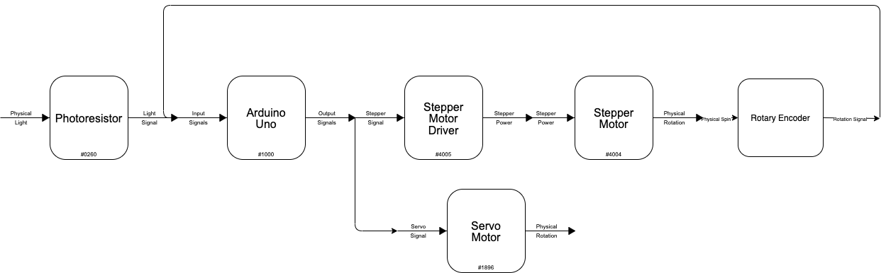
Functional Block Diagram
Schematic Diagrams
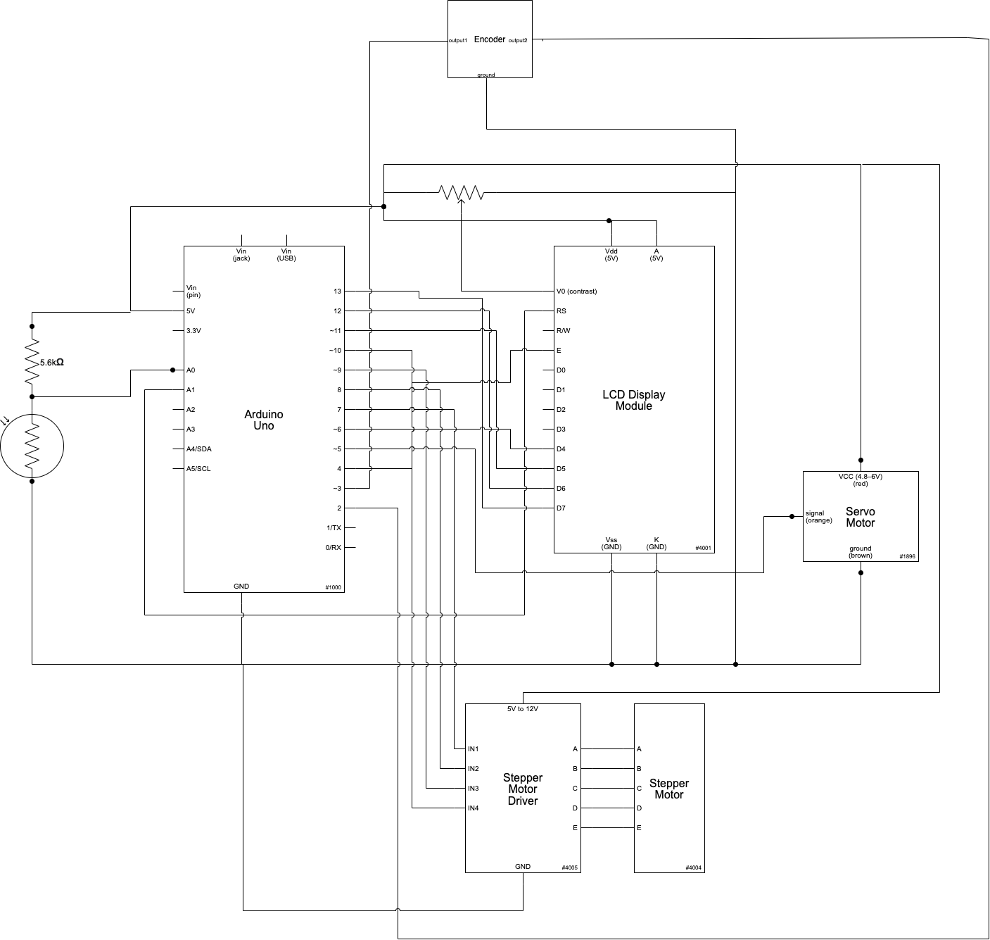
Nicole’s electrical schematic
*a few of Kevin’s pins are slightly different (see code), but the wiring is identical otherwise
Code:
Nicole’s Code
/*
   60-223, Project 1: Double Transducer
   Nicole Yu (nvy) Kevin Bender (kbender1)

   Description:
   This device detects the amount of light through a photoresistor, and
   sends that signal to the stepper motor driver and stepper motor,
   which turns the rotary encoder at a certain speed. The rotary encoder
   determines how far it was rotated in the span of 2 seconds, and sends
   that data to the servo motor, which based on the data, turns to a
   certain angle (orientation).


   Pin mapping:

   Arduino pin | type   | description
   ------------|--------|-------------
   A0            input     photoresistor
   2             input     rotary encoder pin A
   3             input     rotary encoder pin B
   5             output    servo motor
   7             input     stepper motor IN1
   8             input     stepper motor IN2
   9             input     stepper motor IN3
   10            input     stepper motor IN4
   A1            output    LCD RS
   4             output    LCD Enable
   6             output    LCD D4
   11            output    LCD D5
   12            output    LCD D6
   13            output    LCD D7

   Sources:
   1) How to wire and program the LCD from the Elgoo website:
   https://drive.google.com/drive/folders/1BUe40Ibb9Bzi1JwRKywO1PCXBMzkFXm7?usp=sharing
   2) I borrowed heavily from this Stepper motor library
   and code: https://www.arduino.cc/en/Tutorial/LibraryExamples/StepperSpeedControl
   3) I followed this tutorial and borrowed heavily its code:
   https://www.seeedstudio.com/blog/2020/01/19/rotary-encoders-how-it-works-how-to-use-with-arduino/
   4) I referenced the Canvas modules to refresh on how to wire and
   code for a photoresistor and servo
*/

// LIBRARIES
#include <Encoder.h>
#include <Stepper.h>
#include <Servo.h>
#include <LiquidCrystal.h>

// VARIABLES
const int PHOTOPIN = A0; // photoresistor pin
const int DOORMOTORPIN = 5; // servo motor pin
const int stepsPerRevolution = 200; // stepper motor's
const int WAIT = 2000; // 2 seconds
unsigned long timerVariable = 0;
int orientation;
long oldPosition  = -999;

// initialize library code
LiquidCrystal lcd(A1, 4, 6, 11, 12, 13);
Stepper myStepper(stepsPerRevolution, 7, 8, 9, 10);
Encoder myEnc(2, 3);
Servo doorMotor;


void setup() {

  // set up the LCD's number of columns and rows:
  lcd.begin(16, 2);

  // servo
  doorMotor.attach(DOORMOTORPIN);

}

void loop() {

  // PHOTORESISTOR
  int photoVal = analogRead(PHOTOPIN);

  // STEPPER MOTOR
  int motorSpeed = map(photoVal, 0, 1023, 0, 100);
  if (motorSpeed > 0) {

    myStepper.setSpeed(motorSpeed);
    myStepper.step(stepsPerRevolution / 100);

    // ROTARY ENCODER
    long newPosition = myEnc.read();

    // SERVO
    int orientation = map(newPosition, 0, 17, 10, 170); // the 17 is a placeholder,
    // I haven't seen the rotary encoder go past 16

    // Sees at 2 seconds how far rotary encoder turned
    if (millis() - timerVariable > WAIT) {

      doorMotor.write(orientation);
      myEnc.write(0); // resets encoder to 0

      // LCD
      // update LCD here
      lcd.setCursor(0, 0);
      lcd.print("i:"); // input
      lcd.print(photoVal);
      lcd.print(" "); // solution to non erasing problem

      lcd.setCursor(8, 0);
      lcd.print("m1:"); // middle step 1
      lcd.print(motorSpeed);
      lcd.print(" ");

      lcd.setCursor(0, 1);
      lcd.print("m2:"); // middle step 2
      lcd.print(newPosition);
      lcd.print("  ");

      lcd.setCursor(8, 1);
      lcd.print("o:"); // output
      lcd.print(orientation);
      lcd.print(" ");


      timerVariable = millis();

    }

    // not > 2 seconds, update the old position
    else {
      if (newPosition != oldPosition) {
        oldPosition = newPosition;
      }

    }
  }
}
/*
 * 60-223, Project 1
 * Kevin Bender (kbender1)
 * time spent: ~8 hours
 *
 * Collaboration and sources:
 * 1) Nicole Yu and I worked together on the idea and
 *  electrical design, coded separately (other than tinkercad)
 * 2) I borrowed from the Elegoo starter kit lesson 2.3 for the
 *    LCD
 * 3) I borrowed from the Encoder library examples
 * 6) I borrowed from the stepper library examples
 *
 * Challenge(s): This project took a lot of learning and research
 *  as it combined everything we had learned so far about
 *  Arduino and electronics. The challenges came in the form
 *  of trying to figure out how to use the LCD which didn't work
 *  with the manufacturer-recommended wiring of 3.3v and with the
 *  stepper motor which was much weaker than expected.
 *
 * Next time: I will try to learn more about potential inputs/outputs
 * and possibly try them out in advance. A lot of suffering could
 * have been saved by doing this with the stepper motor
 *
 * Description: Object detects light level, based on how intense light is it would cause a motor to spin fast/slow,
 * and that speed would then affect the orientation of the servo motor “dial” (from encoder)
 *
 * Pin mapping:
 *
 * Arduino pin | type   | description
 * ------------|--------|-------------
 * A0            input     Photoresistor as initial input
 * 1             input     rotary encoder pin A for middle step input
 * 13            input     rotary encoder pin B
 * 2             output    Stepper motor driver pin A as middle step output
 * 3             output    Stepper motor driver pin B
 * 4             output    Stepper motor driver pin C
 * 5             output    Stepper motor driver pin D
 * 6             output    servo motor for final output
 * 7             input     pushbutton to activate lights
 * 8             output    LCD pin A
 * 9             output    LCD pin B
 * 10             output    LCD pin C
 * 11             output    LCD pin D
 * 12             output    LCD pin E
 */

// include the library code:
#include <LiquidCrystal.h>
#include <Encoder.h>
#include <Stepper.h>
#include <Servo.h>

const int stepsPerRevolution = 200;

const int ENC1 = 1;
const int ENC2 = 13;

const int LCD1 = 7;
const int LCD2 = 8;
const int LCD3 = 9;
const int LCD4 = 10;
const int LCD5 = 11;
const int LCD6 = 12;

const int STEP1 = 2;
const int STEP2 = 3;
const int STEP3 = 4;
const int STEP4 = 5;

const int SERVOPIN = 6;

const int PHOTORESISTOR = A0;
// initialize the library with the numbers of the interface pins
LiquidCrystal lcd(LCD1, LCD2, LCD3, LCD4, LCD5, LCD6);
Encoder myEnc(ENC1, ENC2);
Stepper myStepper(stepsPerRevolution, STEP1, STEP2, STEP3, STEP4);
Servo myservo;

void setup() {
  myservo.attach(SERVOPIN);
  // put your setup code here, to run once:
  lcd.begin(16, 2);
  // Print a message to the LCD.
  pinMode(PHOTORESISTOR, INPUT);

}


void loop() {
  long t0 = millis();
  long speed = 0;
  long lastPos = myEnc.read();
  while (true) {
    long t = millis();
    myEnc.read();
     int motorSpeed = map(analogRead(PHOTORESISTOR), 0, 1023, 0, 100);
    // set the motor speed:
    if (motorSpeed > 0) {
    myStepper.setSpeed(motorSpeed);
    // step 1/100 of a revolution:
    myStepper.step(stepsPerRevolution / 100);
  }
    if (t - t0 > 1000) {
      long curPos = myEnc.read();
      speed = abs(curPos-lastPos);
      long pos = map(speed,0,15,0,180);
      myservo.write(pos);
      lastPos = curPos;
      lcd.setCursor(0, 0);
      lcd.print( "i: " + String(map(analogRead(PHOTORESISTOR), 0, 1023, 0, 99)) + " m: "+String(motorSpeed));
      lcd.setCursor(0, 1);

      lcd.print("  " + String(speed)+ "  o: " +  String(map(pos,0,180,0,99)));
      // print the number of seconds since reset:
      t0 = t;
    }
  }

}