
Initial Sketches and Block Diagram:
![]()
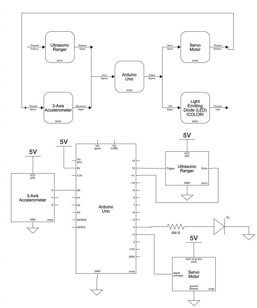
For the middle step on our transducer, we were deciding between having a servo drive a potentiometer, having a servo drive a platform with an accelerometer, and having a speaker output measured by a microphone. We ended up deciding on the servo – accelerometer pair, but also made a servo – potentiometer prototype as an initial version to test various components on.
TinkerCAD Exploration
Ultrasonic to Potentiometer to LED
Erica’s Version
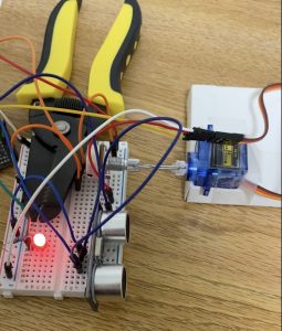
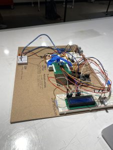
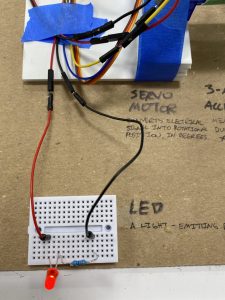
This was the initial double transducer design we had. My project was barely held together. I had to tape the micro servo to the Maker Cards and used the wire cutter to hold the breadboard down so that the board wouldn’t lift when the servo motor turned the potentiometer.
Using an ultrasonic ranger, I detected the distance from the build. The ranger determined the angle of the servo motor which was attached to the potentiometer. This potentiometer then determined the brightness of the LED.
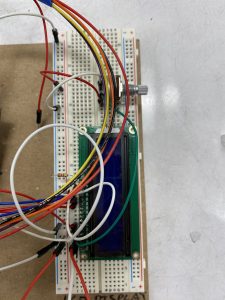
By replacing the small breadboard with a bigger version, I was able to make a less cluttered double transducer.
Here is a video of my working double transducer. I displayed the input and output values using the Serial Monitor on Arduino. Through the video, you can see that the light turns brighter when the box is closer to the ultrasonic sensor and dimmer when the box is further away.
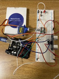
Eric’s Version
![]()
Similar to Erica’s version, I connected the servo to the potentiometer through a paperclip and servo mount.
Due to the noisiness of the ultrasonic data, I added a moving average filter to smooth that out. Also, I found out the analog input pins do not have PWM capabilities which was a helpful reference for later.
Ultrasonic to Accelerometer to LED
Erica’s Contribution
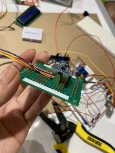
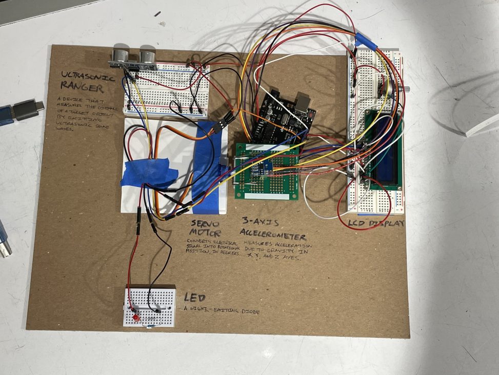
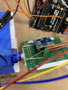
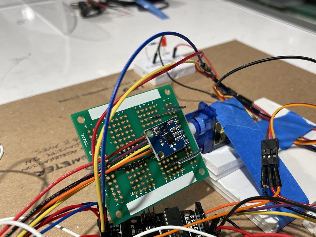
We soldered the 3-axis accelerometer and a terminal, ensuring a strong connection for our middle step in the transducer. The final configuration of the objects on the board was tightly put together, with the 3-axis accelerometer acting like a protective hood over the terminal.
For the final project, I also configured the LCD to display the outputs. Working with the LCD was difficult because of the intense amount of wiring, but through following tutorials online, I was able to successfully have the LCD display our input and output values.
Eric’s Contribution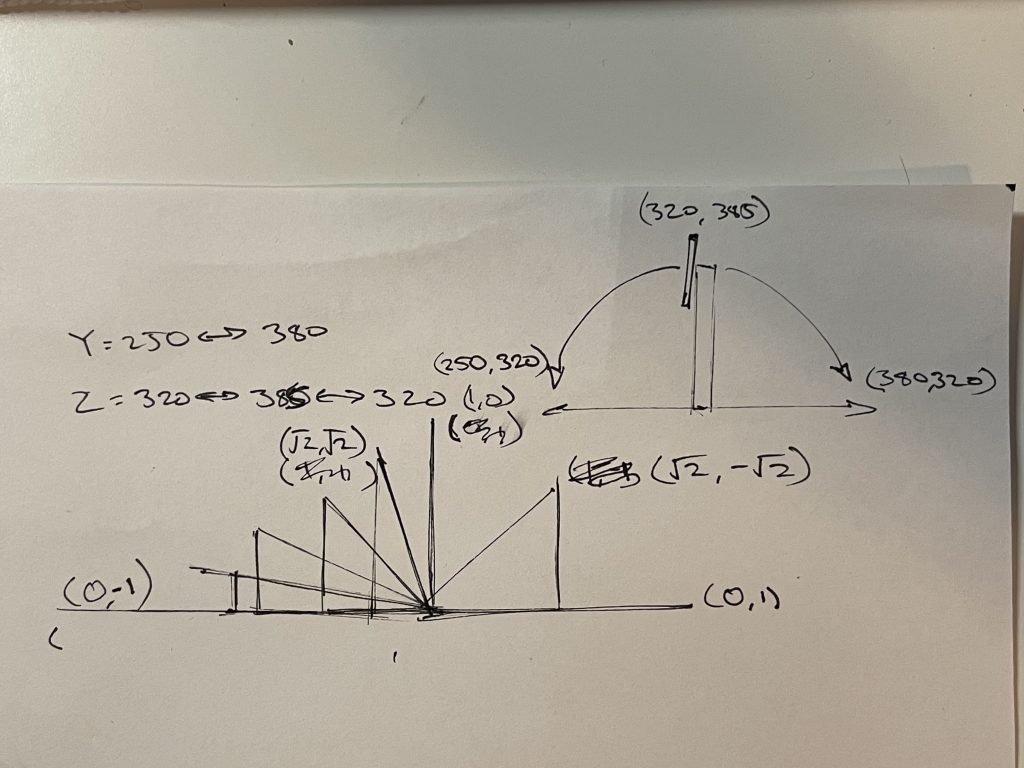
To convert the accelerometer’s 3-axis acceleration readings into an angle value that could be interpreted as a parallel to the servo’s rotation, there was a little trig involved (taking an inverse tangent of two axes, modeled after the unit circle). The above clip is me testing the accelerometer’s analog inputs and figuring out the range of raw inputs to map to -1 and 1 for both x and y values on the unit circle.
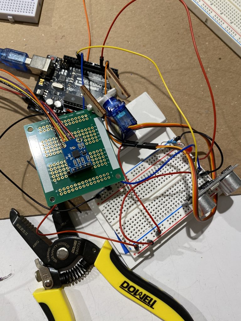
For the final transducer, I soldered part of the proto-board that the accelerometer attaches to and mounted the the board onto the servo arm via paper clips.
Detail Shots of Final Project
Code
/*
 * 60-223, Project 1
 * Eric Zhao (ezhao2), Erica Fu (efu)
 * time spent: 20 hours
 *
 * Collaboration and sources:
 * 1) Eric and Erica worked together from planning, coding, to building the final project
 * 2) Zach assisted many times throughout the process
 * 3) We borrowed heavily from the Arduino guide to use the LiquidCrystal library
 * website link: https://www.arduino.cc/en/Tutorial/LibraryExamples/HelloWorld
 * 4) We implemented this moving average filter to smooth out ultrasonic data values:
 * https://courses.ideate.cmu.edu/60-223/s2021/tutorials/code-bites#exponential-moving-average-filter
 * Challenge(s): Since there are many wires, the wiring often became jumbled and confusing.
 * Also, the LCD display could only use certain pins, causing us to have to rewire the whole project.
 * The connection from the servo motor to the 3-axis-accelerometer was also quite difficult since
 * we had to customize parts and eventually settle for using a paperclip to make a mechanical connection.
 *
 * Next time: We will organize wiring better so that the circut is clearer so that any change
 * of wiring will be less confusing.
 *To prevent breaking any more Arduinos, Erica will double check the wiring to ensure that
 * there is minimal damage caused in the future.
 *
 * Description: The entire breadboard is mounted to a servo motor whose output shaft is connected to a
 * rigid vertical structure. Depending on the input voltage from the ultrasonic sensor, the servo motor
 * will output a corresponding angle, causing the entire breadboard to rotate. An accelerometer attached
 * to the breadboard will read the tilt angle of the breadboard caused by the servo. The input voltage
 * will determine the output voltage of the LED.
 *
 * Pin mapping:
 *
 * Arduino pin | type   | description
 * ------------|--------|-------------
 * A0            input     xInput of the 3-axis accelerometer
 * A1            input     yInput of the 3-axis accelerometer
 * A2            input     zInput of the 3-axis accelerometer
 * 9             output    mini servo motor
 * 6             output    red LED
 * 12            output    rs pin for the LCD monitor
 * 11            output    en pin for the LCD monitor
 * 5             output    d4 pin for the LCD monitor
 * 4             output    d5 pin for the LCD monitor
 * 3             output    d6 pin for the LCD monitor
 * 2             output    d7 pin for the LCD monitor
 *
 */

#include <Servo.h>
#include <NewPing.h>
#include <LiquidCrystal.h>

#define TRIGGER_PIN 8
#define ECHO_PIN 7
#define MAX_DISTANCE 75

NewPing sonar(TRIGGER_PIN, ECHO_PIN, MAX_DISTANCE);

const int waitTime = 250;
long prevTime = 0;

const int xInput = A0;
const int yInput = A1;
const int zInput = A2;
const int SERVOPIN = 9;
const int LED = 6;
Servo SERVO;

float filtered_val = 0;  // this variable, of type float (decimal), holds the filtered sensor value
const float PREV_WEIGHT = 0.8; // this variable, of type float (decimal), determines the previously filtered value's weight.
const float CUR_WEIGHT = 1 - PREV_WEIGHT; // this variable, of type float (decimal), determines the current sample's weight.
const int SENSOR_PIN = A0; // this variable, of type int, determines the sensor's pin.

// initialize the library by associating any needed LCD interface pin
// with the arduino pin number it is connected to
const int rs = 12, en = 11, d4 = 5, d5 = 4, d6 = 3, d7 = 2;
LiquidCrystal lcd(rs, en, d4, d5, d6, d7);

void setup() {
  // put your setup code here, to run once:
  pinMode(xInput, INPUT);
  pinMode(yInput, INPUT);
  pinMode(zInput, INPUT);
  pinMode(LED, OUTPUT);
  SERVO.attach(SERVOPIN);
  Serial.begin(115200);

  // set up the LCD's number of columns and rows:
  lcd.begin(16, 2);
}

void loop() {
  // put your main code here, to run repeatedly:

  delay(50);
  //raw data by axis from accelerometer
  int x = analogRead(xInput);
  int y = analogRead(yInput);
  int z = analogRead(zInput);
  //data from accelerometer, mapped to units -1000 to 1000
  int xVect = map(x, 260, 390, -1000, 1000);
  int yVect = map(y, 250, 380, -1000, 1000);
  int zVect = map(z, 320, 385, 0, 1000);
  //below variables are the above vars but divided by 1000 to achieve unit circle
  float xVectUnbound = xVect/1000.0;
  float yVectUnbound = yVect/1000.0;
  float zVectUnbound = zVect/1000.0;
  //constraining final readings to unit circle -1 to 1
  float xVectFinal = constrain(xVectUnbound, -1, 1);
  float yVectFinal = constrain(yVectUnbound, -1, 1);
  float zVectFinal = constrain(zVectUnbound, 0, 1);
  //final arctan value (takes two axes and converts into degrees)
  float degreeVal = atan2(xVectFinal, zVectFinal) * 180/PI;

  //creates a weighted reading
  float cur_reading = sonar.ping_cm();
  if(cur_reading != 0){
    filtered_val = filtered_val * PREV_WEIGHT + cur_reading * CUR_WEIGHT;
  }

  //takes a smoothed out sonar reading and converts to servo degrees
  int servoVal = map(filtered_val, 0, 75, 0, 180);
  //takes accelerometer degree reading and converts to
  int outputVal = map(degreeVal, -55, 90, 0, 255);
  if(cur_reading != 0 && servoVal > 0){
    SERVO.write(servoVal);
  }

  if(outputVal > 0){
    analogWrite(LED, outputVal);
  }

  int inputDisplay = map(filtered_val, 0, 75, 0, 100);
  int middleActDisplay = map(servoVal, 0, 180, 0, 100);
  int middleSensorDisplay = map(outputVal, 0, 255, 0, 100);

  if(millis() - prevTime > waitTime){
    //outputs data to LCD display 4 times a second
    lcd.setCursor(0,0);
    lcd.print((String)"i:"+ inputDisplay);
    lcd.setCursor(5,0);
    lcd.print((String)"m:" + middleActDisplay);
    lcd.setCursor(7,1);
    lcd.print(middleSensorDisplay);
    lcd.setCursor(11,1);
    lcd.print((String)"o:" + middleSensorDisplay);

    prevTime = millis();
  }

}
Reflection
We found a lot more issues throughout the span of this project than either of us imagined would happen! Different libraries conflicted with each other (for example, the Servo library shut down certain pins that the NewPing ultrasonic library utilized). Mechanical connections between certain parts were difficult to make robust enough to handle the servo’s torque; we ended up using paperclips for a lot of these as compared to tape, which was a lot weaker.