Tinkercad Video:
Tinkercad does not have a lot of components that are present in the real life version, so there are some fake data simulation. In real life, our first sensor is an accelerometer, but we simulated it with a potentiometer. The values are mapped to be in between 0-100 to mimic values we could get from our accelerometer. From there, the data is mapped to a value between 130-180 so serve as an angle for the servo motor. In real life, the servo motor would move an object in front of an ultrasonic ranger, but instead, we have to fake the simulation. The distance output from the ultrasonic ranger is then mapped to a value between 100 and 600 to serve as tone for the buzzer.
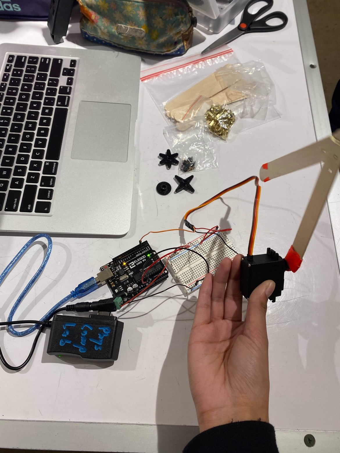
Photos for Scale:
Shuyu:
Vishnu:
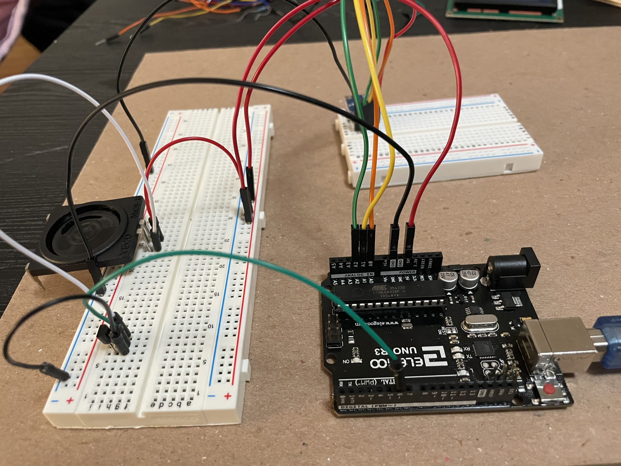
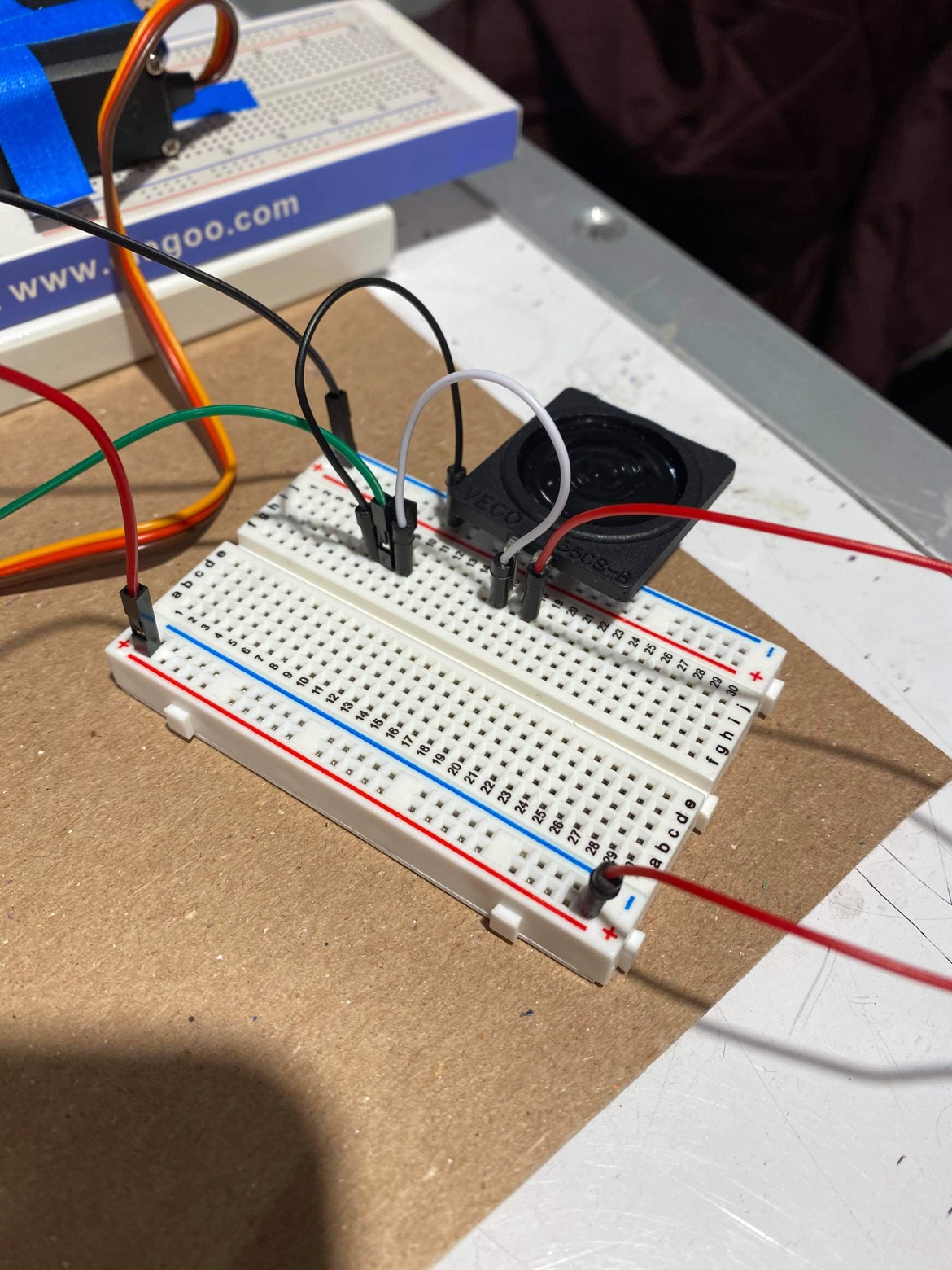
Detail Photos
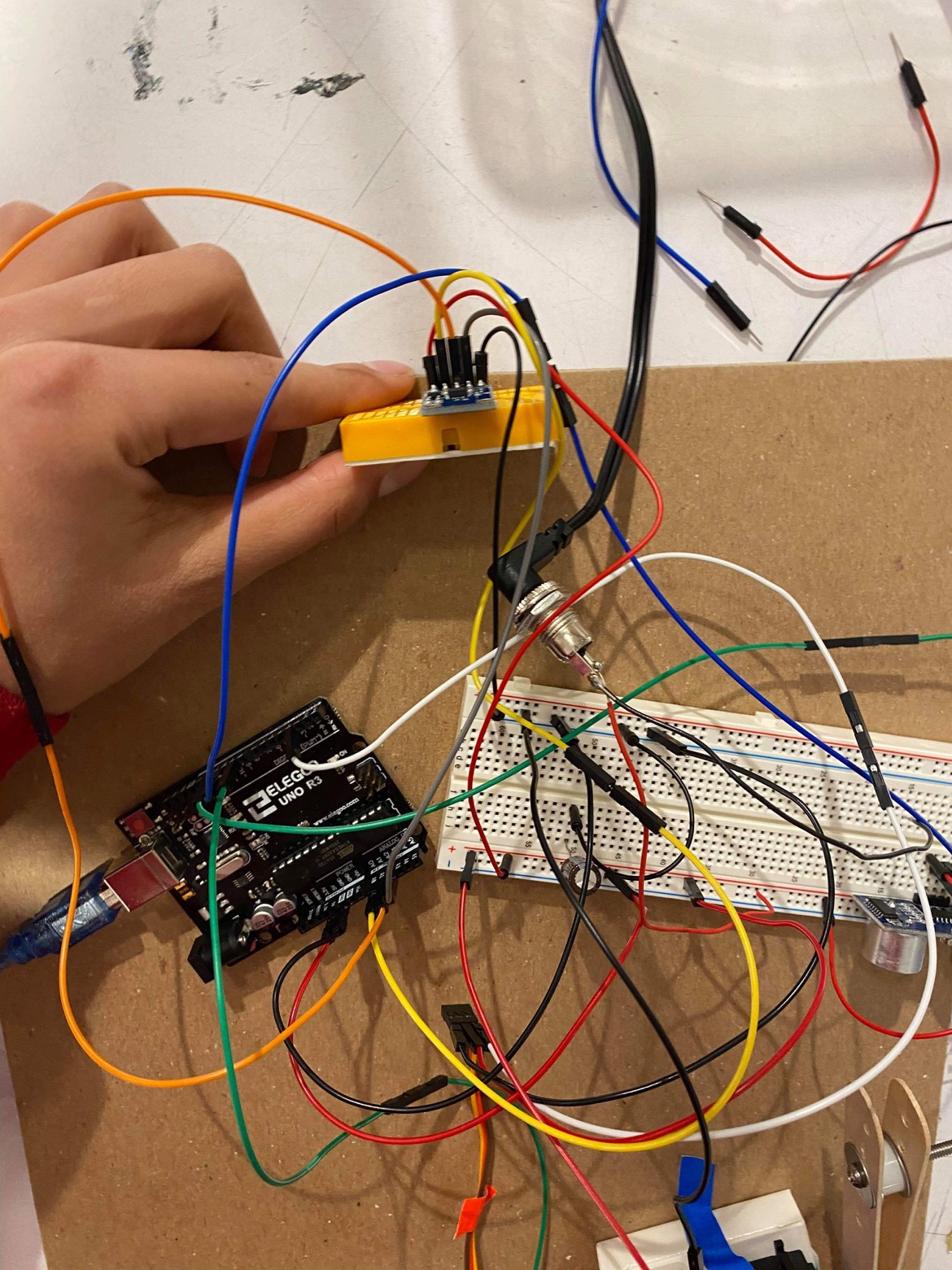
Initially, getting data from the accelerometer was a little foreign, so it took some thinking on how we would utilize the data.
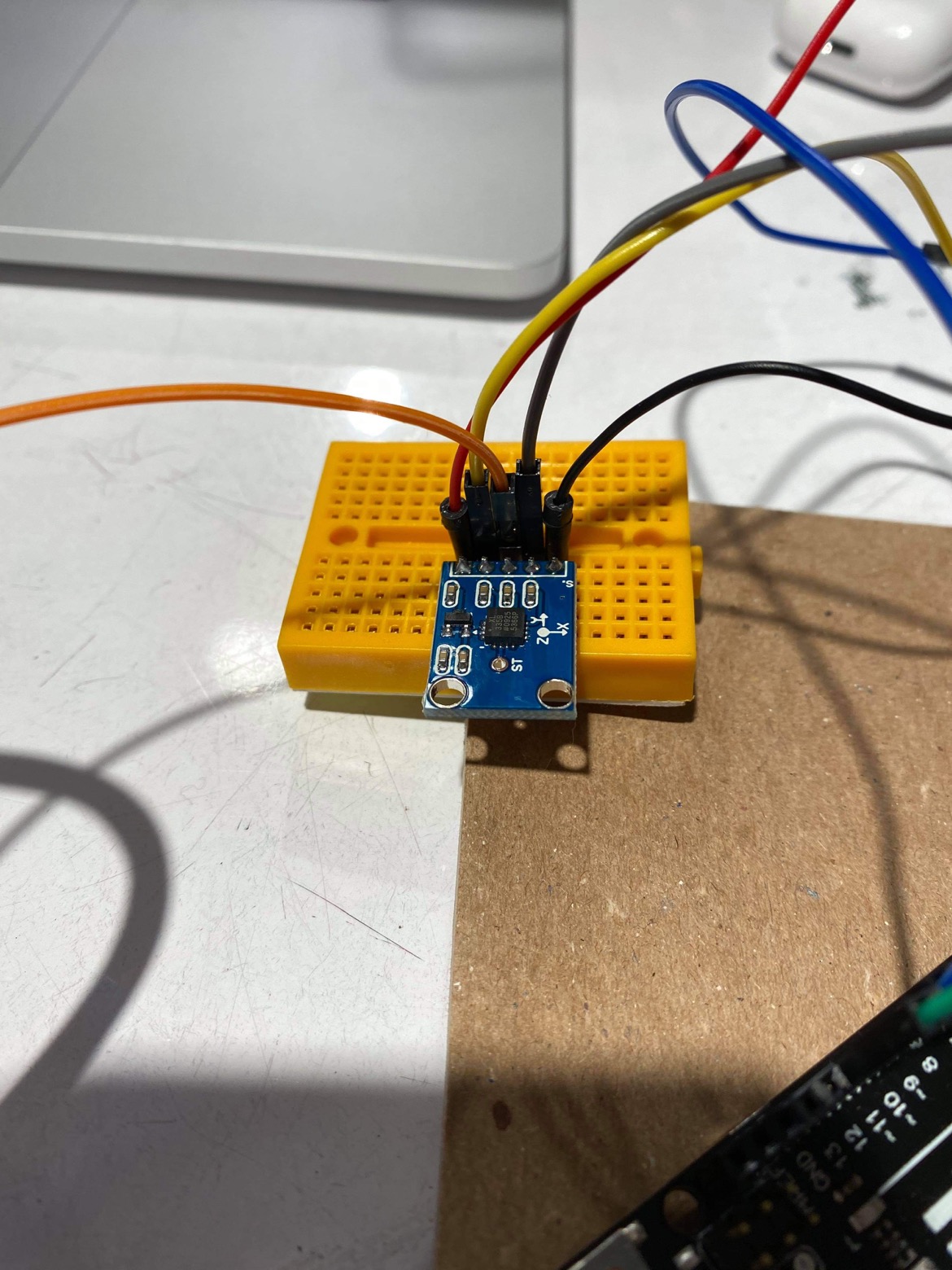
The accelerometer was a new tool to us, so we had to research on how to wire and write code for it.
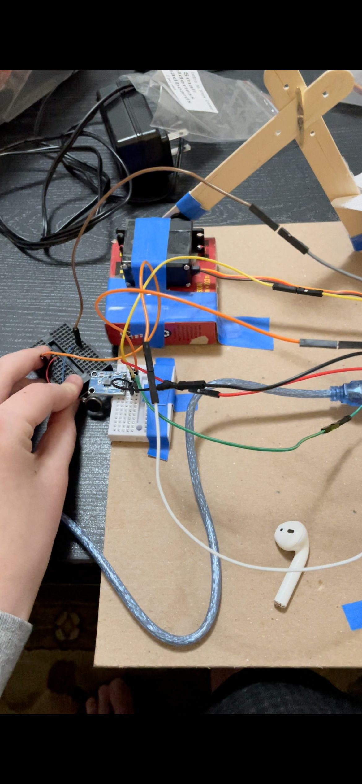
Testing everything with a pancake motor at the end.
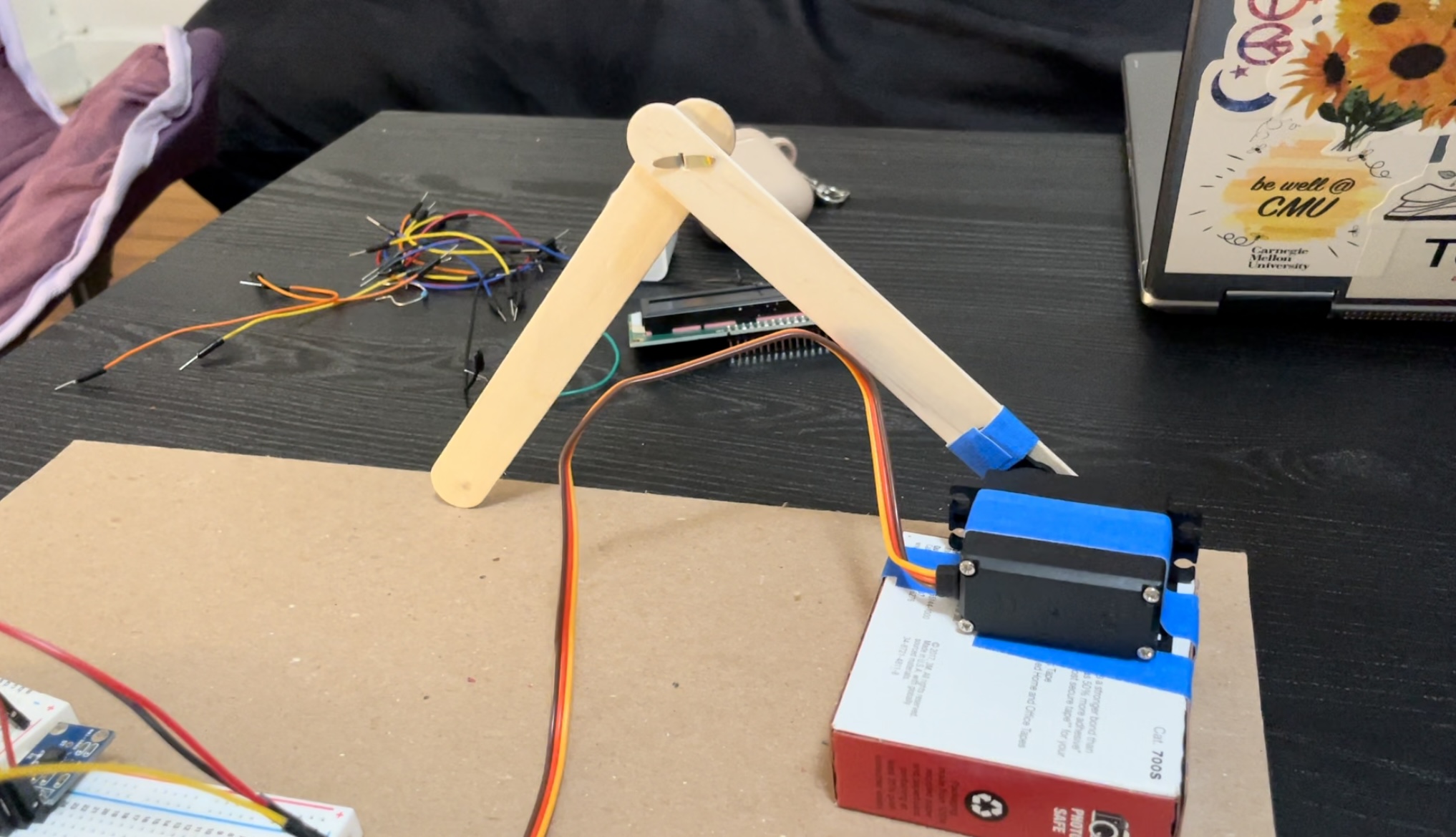
Building the arm that extend back and forth had its mechanical difficulties. It took a while to troubleshoot how far the arm could extend.
Videos:
Shuyu:
Vishnu:
Narrative Description:
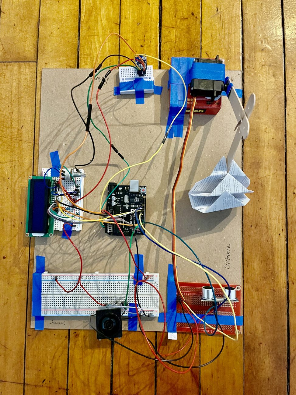
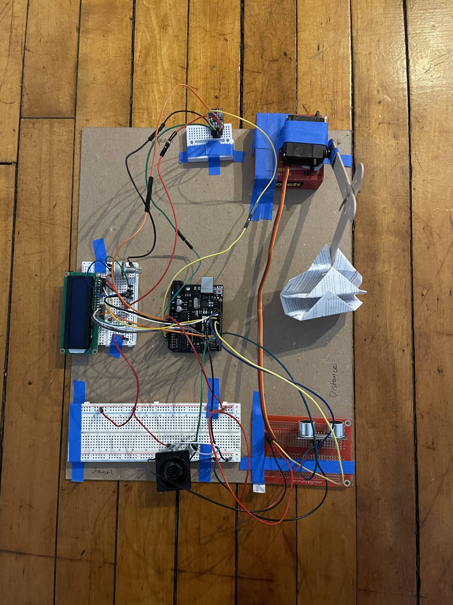
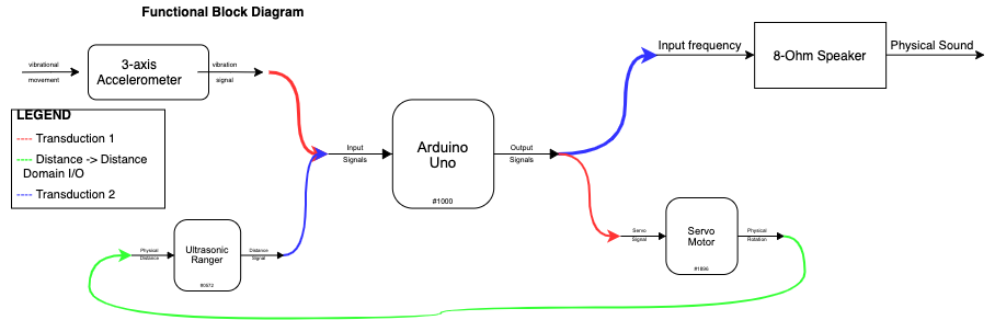
Our double transducer takes in vibration as an input (via a 3-axis accelerometer), and converts that input to an angle for a servo motor. The servo motor is attached to a popsicle stick “arm” that extends based on the angle. An ultrasonic ranger detects how far the popsicle sticks are from it and the resulting distance (cm) is converted into a tone for an 8-ohm speaker.
Progress Photos:
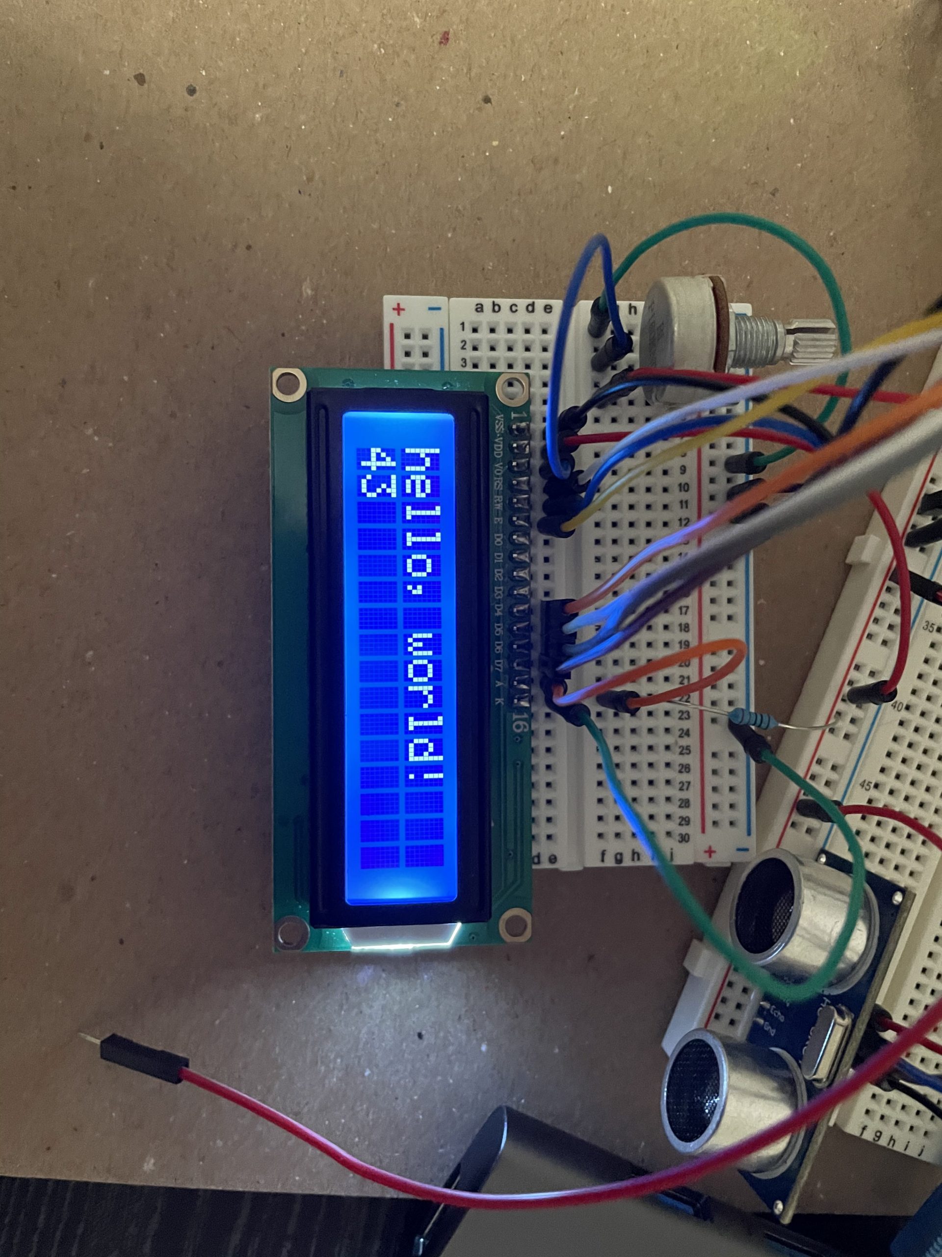
Shuyu: This was when I first successfully wired and ran some code through the LCD display. It was super exciting because the wiring was a little intense and something could have easily gone wrong.
Shuyu: Using a transistor to wire a speaker was a new concept and wiring it correctly was a major step in the overall project.
Vishnu: Troubleshooting the popsicle arm and trying to find a good angle range. I ended up building barriers for it.
Vishnu: Wiring the speaker had some challenges because wires were not connected into the right ports.
Discussion:
The entire process of brainstorming, planning, and creating the double transducer was filled with its unique set of problems and triumphs. From the beginning, we were not familiar with vibration as an input and we were not sure how ambitious we should be with our middle step. We played around with a couple of ideas, including a basic vibration to light to sound workflow. Excluding the vibration portion, we were confident we could get the “light” middle step (LED + photoresistor) to work and output sound; this would serve as a good backup plan in case a more ambitious setup failed.
The ambitious idea we settled on was a system of vibration to movement to sound. We decided to split the “movement” into two parts: One part performing the movement (a Servo motor with a lever attached), and the other part sensing proximity and outputting a distance value (via an ultrasonic ranger). We found that while the idea was simple enough, the middle step ran into significant challenges.
Most notably, we had to restrict the servo motor from its total range, in order to constrain it to the board as well as prevent it from ripping out of its supports. This was mainly achieved through trial and error, and each of us had slightly different ranges based on the physical layout of our board and device.
With help from Zach, we realized that a good stand-in for a vibration sensor was a 3-axis accelerometer. The accelerometer senses the position (X,Y, Z) of the device if it is even slightly shifted. We realized that this could work to our advantage, although we needed to manually manipulate it to achieve the output. We found that because we had to twist the accelerometer around, we had to make sure to bolt the apparatus down through soldering and tape.
This project definitely pushed us to understand the real-world limitations of theoretical concepts. While there were chunks of the project we could neatly resolve in software, there were other parts we simply had to stress-test through empirical trials (such as the servo extension). Overall, we came away with a solid understanding of the relationship between different mediums, as well as the interlocking nature of software and hardware in electronics.
Functional Block Diagram:
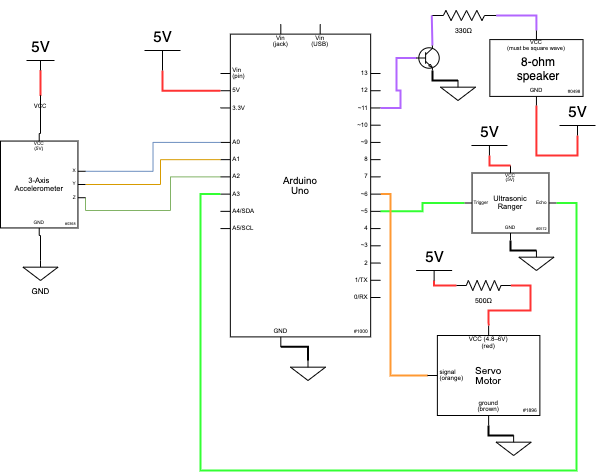
Schematic:
Code:
/*
   60-223, Double Transducer : Vibration to Movement to Sound
   Shuyu Zhang, Vishnu Raghavan

   Description: Our doubel transducer takes in vibration as an input.
   The input is measured by a 3-axis accelerometer. The difference between
   the input from the x-axis and y-axis is then mapped to an angle
   for a servo motor (130-180 degrees). In real life, the servo motor is
   attached to a popsicle arm that will extend based on the angle the servo
   motor moves to. An ultrasonic ranger sits in front of the popsicle arm
   and measures how close or far the arm is from it. The data from the
   ultrasonic ranger is then mapped to a tone (100-600) which is the output
   for a speaker.

   Sources:
   1) Heavily referenced the program on the maker cards website when programming the
   accelerometer
   2) Incorporated some of the code of an example from the HCSR04 library in order
   to read distance with the ultrasonic ranger
   3) Referenced the Servo Motor example from class to program the servo motor
   4) Used LCD Display wiring and program from Arudino Website to program the
   LCD Display


   Pin mapping:

   Arduino pin | type   | description
   ------------|--------|-------------
   12     LCD Pin  Used to initialize the LiquidCrystal Library
   11     LCD Pin  Used to initialize the LiquidCrystal Library
   5      LCD Pin  Used to initialize the LiquidCrystal Library
   4      LCD Pin  Used to initialize the LiquidCrystal Library
   3      LCD Pin  Used to initialize the LiquidCrystal Library
   2      LCD Pin  Used to initialize the LiquidCrystal Library
   9      Output   Servo Motor pin
   6      Output   Buzzer pin
   13     Input    Trigger Pin in the Ultrasonic ranger
   7      Input    Echo Pin in the Unltrasonic ranger
   A0     Input    Analog input pin for X movement
   A1     Input .  Analog input pin for Y movement
   A2     Input    Analog input pin for Z movement

*/

#include <HCSR04.h>
#include <Servo.h>
#include <LiquidCrystal.h>

const int rs = 12, en = 11, d4 = 5, d5 = 4, d6 = 3, d7 = 2;
LiquidCrystal lcd(rs, en, d4, d5, d6, d7);

Servo motor;
byte triggerPin = 13;
byte echoPin = 7;
const int SERVOPIN = 9; //Analog
const int BUZZER = 6; //Analog output in for 8Ω Speaker
const int ACCELXPIN = A0; // Analog input pin for X movement
const int ACCELYPIN = A1; // Analog input pin for Y movement
const int ACCELZPIN = A2; // Analog input pin for Z movement
const int TIMERWAIT = 1000;
const int MOTORWAIT = 200;

// Variables to keep track of the current positions
int accelXPos = 0;
int accelYPos = 0;
int accelZPos = 0;
int dist;
int angle;
int currTone;
int accelData;
unsigned long timer = 0;
unsigned long motorTimer = 0;

void setup() {
  Serial.begin(9600);

  //Set up for ultrasonic ranger
  HCSR04.begin(triggerPin, echoPin);

  //Set up for servo motor
  motor.attach(SERVOPIN);

  // Setup the accelerometer inputs
  pinMode(ACCELXPIN, INPUT);
  pinMode(ACCELYPIN, INPUT);
  pinMode(ACCELZPIN, INPUT);

  //Setup for buzzer output
  pinMode(BUZZER, OUTPUT);

  // set up the LCD's number of columns and rows:
  lcd.begin(16, 2);

}

void loop() {

  // Get the current states
  accelXPos = analogRead(ACCELXPIN);
  accelYPos = analogRead(ACCELYPIN);
  accelZPos = analogRead(ACCELZPIN);

  //declares a variable to read distance for ultrasonic ranger
  double* distances = HCSR04.measureDistanceCm();

  accelData = abs(accelXPos - accelYPos); //Gives range of (0-90)

  //Mapping Accelerometer data to an angle
  angle = map(accelData, 0, 90, 130, 180);


  //Set at a delay of 200 milliseconds
  //c
  if (millis() - motorTimer > MOTORWAIT) {
    motorTimer = millis();

    dist = (int)(distances[0]);
    currTone = map(dist, 0, 30, 100, 600);
    tone(BUZZER, currTone);

    //changes angle based on accelerometer input
    //changes tone based on distance
    motor.write(angle);
    delay(200);
    tone(BUZZER, currTone);
    motor.write(angle);
    delay(200);

  }


  //LCD Display Code
  if (millis() - timer > TIMERWAIT) {
    timer = millis();

    lcd.setCursor(8, 1);
    int midSen = map(dist, 0, 30, 0, 99);
    lcd.print(midSen);
    if (midSen > 100) {
      lcd.clear();
    }

    //First Row on LCD
    lcd.setCursor(0, 0);
    lcd.print("i:");
    int input = map(accelData, 0, 90, 0, 99);
    lcd.print(input);
    lcd.setCursor(7, 0);
    lcd.print("m:");
    int midAct = map(angle, 130, 180, 0, 99);
    lcd.print(midAct);

    //Second Row on LCD
    lcd.setCursor(12, 1);
    lcd.print("o:");
    int output = map(currTone, 200, 600, 0, 99);
    lcd.print(output);
  }


}