
Double Transducer
Images
Overall Photos
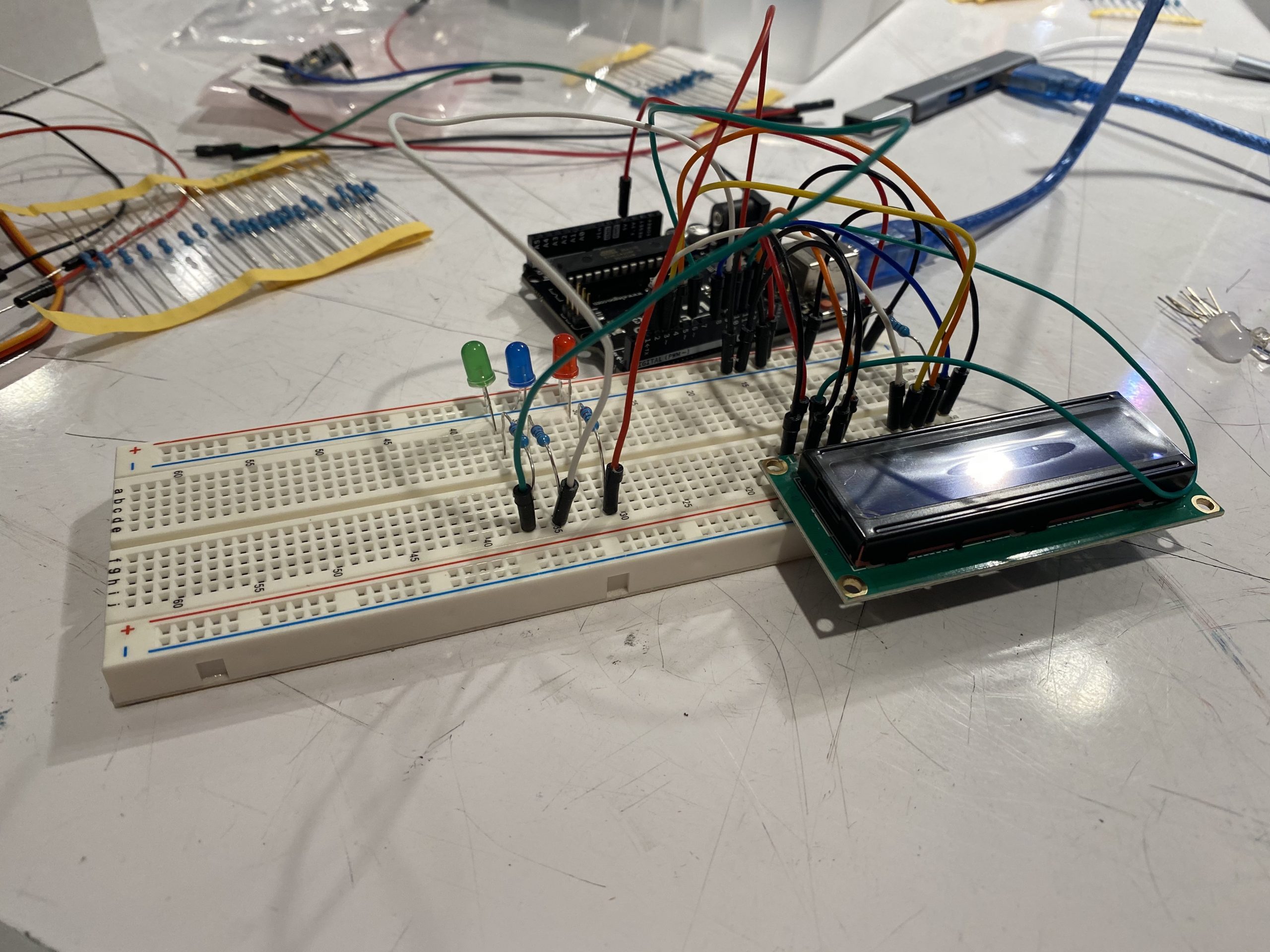
(Jud)
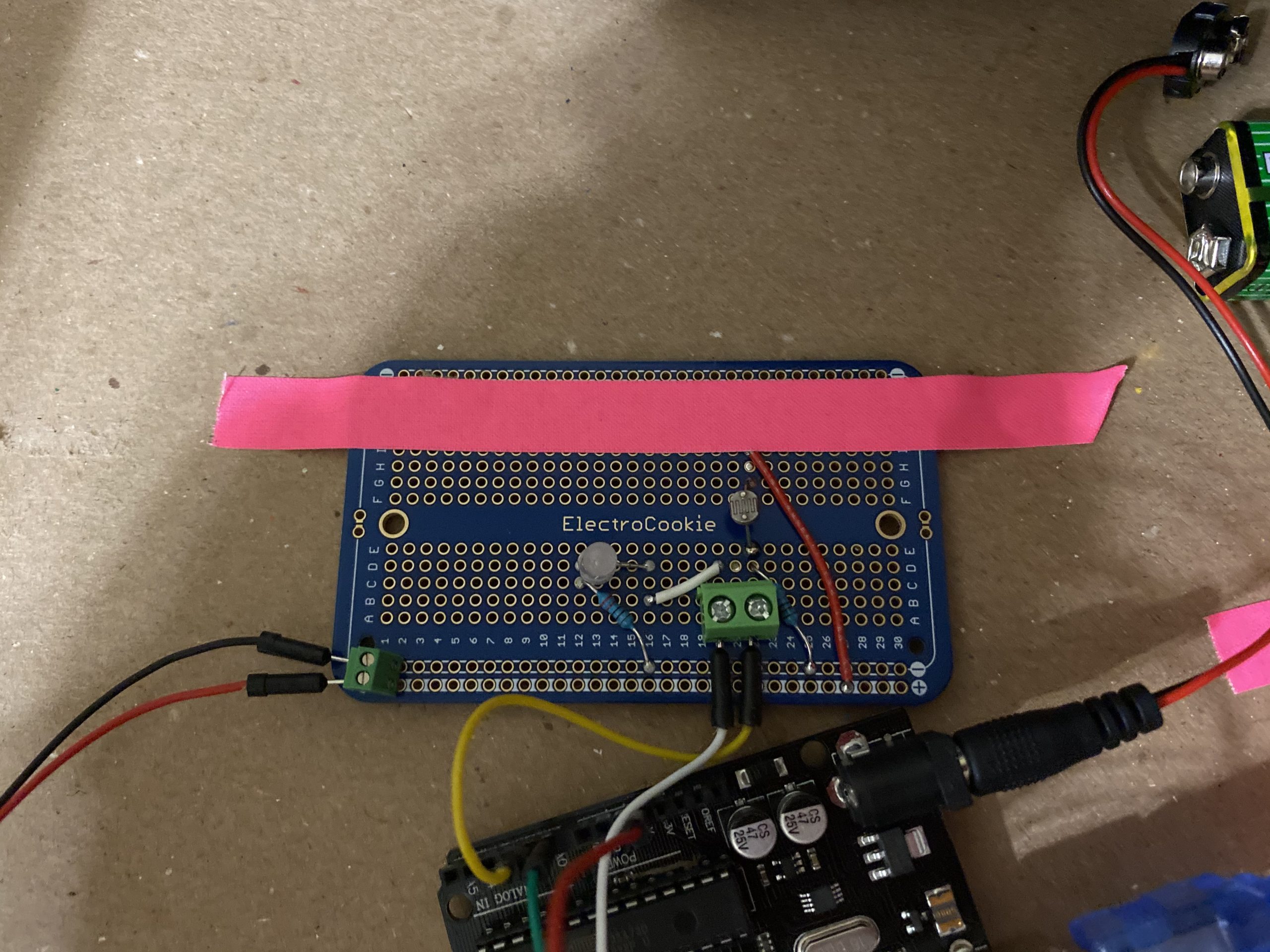
(Jun)
Detail Photos
Transducers in Action
TinkerCAD Simulation
Narrative Description
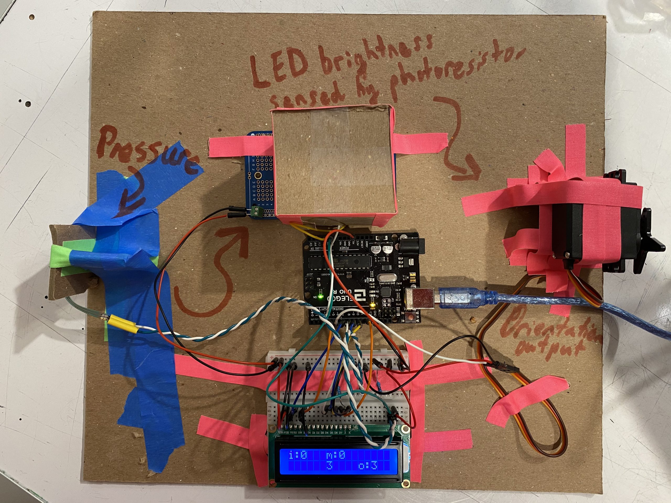
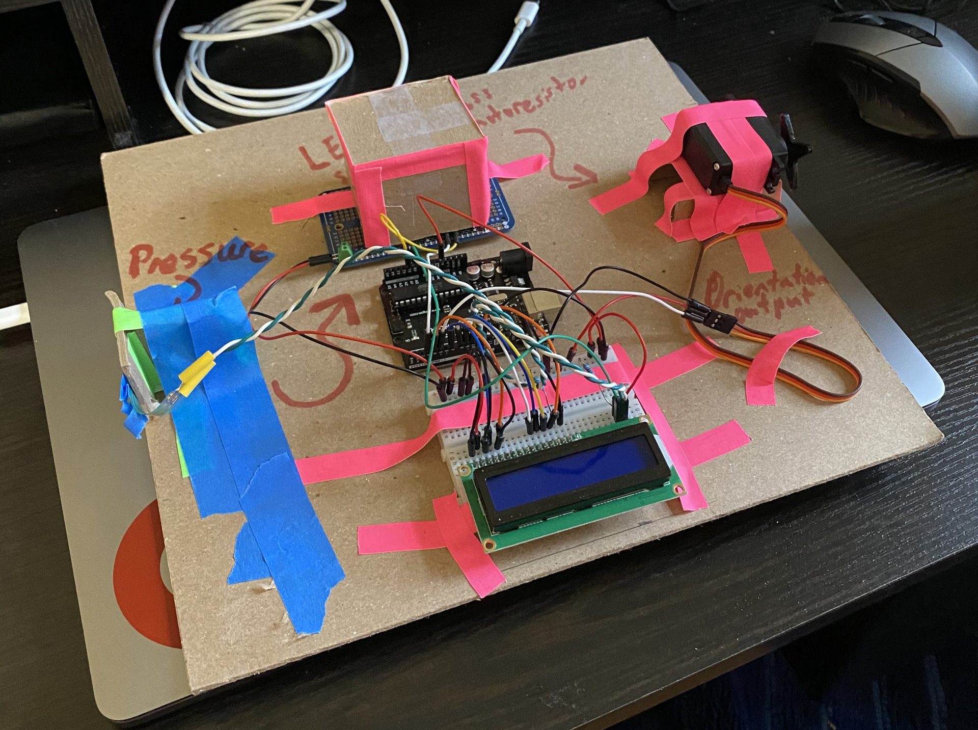
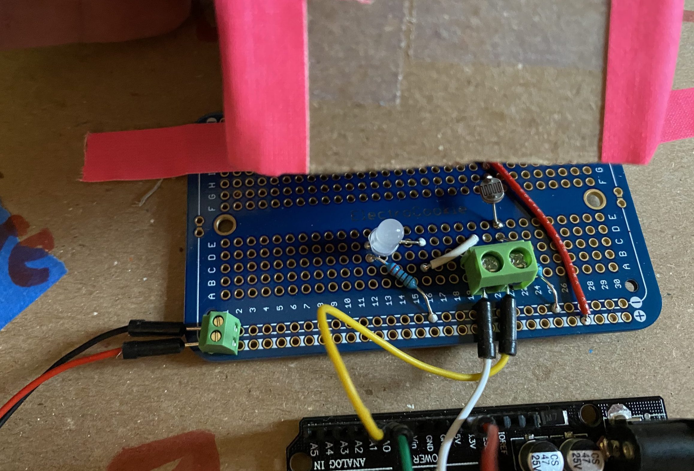
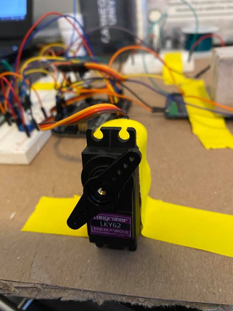
The cardboard stand on the left of the transducer has a pressure sensor attached to it which senses how hard it is pressed. Based off of this pressure, a light inside of the cardboard box turns on to a specific brightness. If the pressure sensor is pushed hard, then the light turns on very bright, and if it is pressed lightly, then the light is very dim. Inside of this box is also a light sensor that senses this change in the clear light’s brightness. According to the amount of change that occurs, a servo on the left side of the mechanism turns around. If the amount of light in the box increases, then the servo rotates counter-clockwise to match this amount of change. As all of this is happening, a display at the bottom of the machine shows the numeric values of all of these actions starting with the pressure sensor in the top left and ending with the servo in the bottom right of the screen.
Process
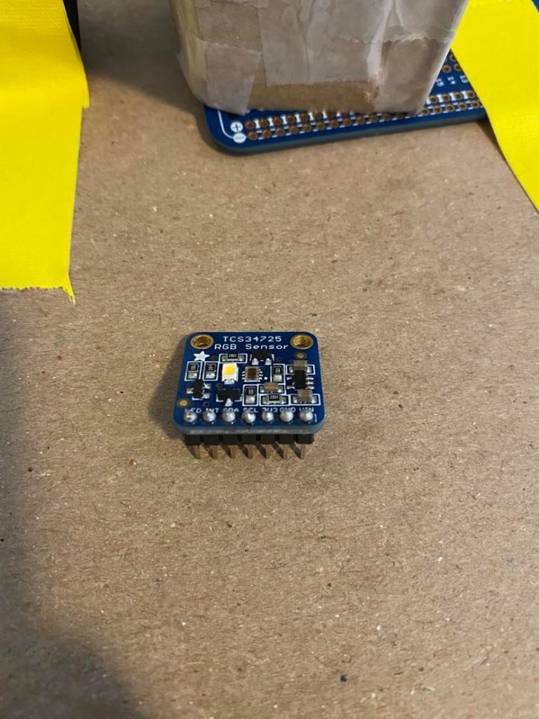
This image shows the soldering of the color sensor that we were originally going to use. The soldering was successfully done, and the device was working, but we decided not to use this sensor.
This image depicts the testing of the color output using three different color LED’s to see what was causing our multi-colored LED issue discussed later on.
This image shows the final step of the soldering process where our switch from color sensing to brightness became permanent.
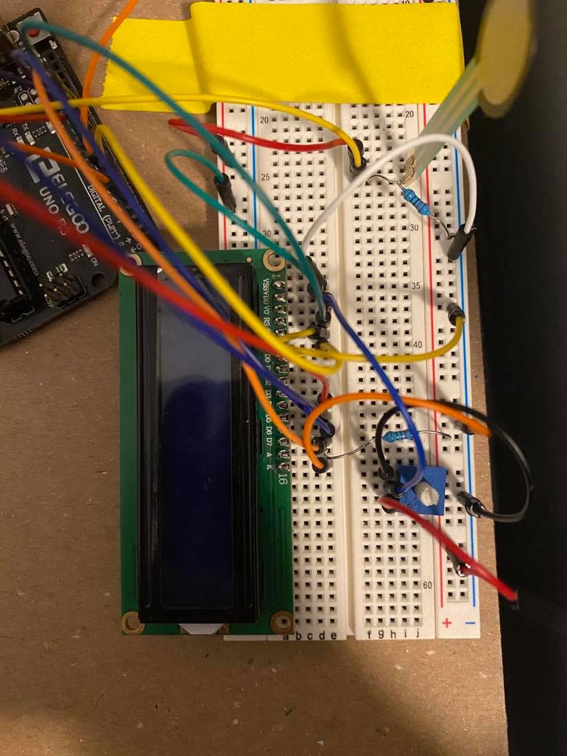
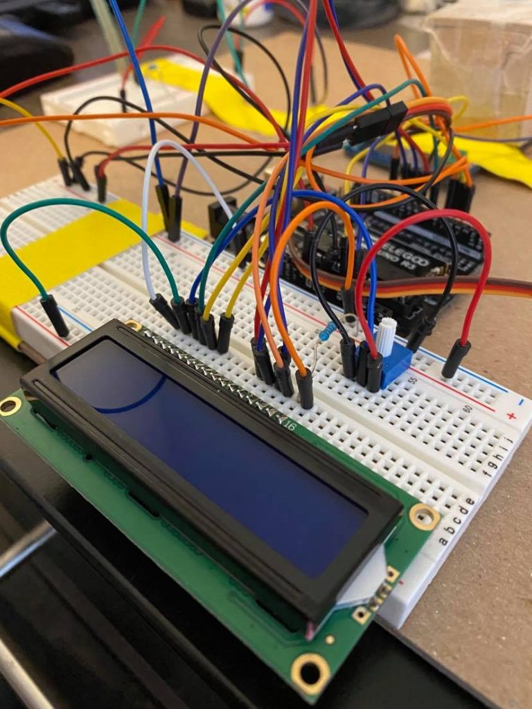
This image shows the process of adding the potentiometer to the LCD in order to adjust its brightness. Initially, the v0 was connected to the ground instead of the potentiometer, and we were not able to adjust its brightness.
Discussion
The hardest part about this project was understanding how to use each of the components and figure out accurate mapping functions to make sure each component was being used to its full potential. The hardest component accomplish this with was the color sensor because of its 3 inputs. Since the color sensor has red, green, and blue inputs, the Force Sensitive Resistor’s (FSR) single output made connecting these two elements very challenging. In the end, after relentlessly searching for algorithms that would accomplish this goal for us, we decided to pursue an alternative method utilizing brightness instead. Reflecting back on this decision, however, it would’ve been a better idea to start out with trying to understand this conversion process and write our own algorithm as opposed to searching the internet for one we could implement. This could have possibly improved our ability to understand these converting algorithms later on if we needed to use them which may have resulted in the final product including this middle sensor.
Apart from this color sensing dilemma, we also ran into issues while trying to use the servo library and analogWrite functionality together. During our first testing stages of the different components, we had the multi-colored LED wired in such a way that it would receive PWM signals from pins 6, 9, and 10. Upon plugging everything in and trying to change the color of the LED, only the LED plugged into pin 6 would produce the desired effect. After lots of time spent trying to debug the circuit, we finally figured out that the issue existed with the way that the servo library interacts with the Arduino. In order for the servo library to function, part of the code disables the analogWrite function for pins 9 and 10 making our original circuit diagram invalid. Just switching the input pin placement for these LED’s fixed our problem entirely.
Reflecting back on the creativity of the project, it would’ve been both easier and more exciting/interesting to only use the red and blue LED’s for the middle step of the transducer. This would not only make the code simpler by removing the need to map one input to three values and back, but it would also have a more physical meaning aligning closer to traditional ways of depicting pressure. Adding this element could have made the transducer a little bit more interactive helping to produce a more meaningful interaction than what this final version creates.
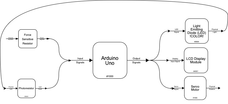
Functional Block Diagram
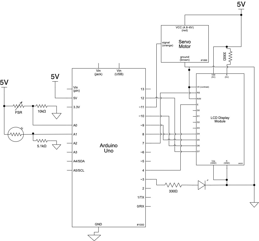
Electrical Schematic
Code
/*
   60-223, Double Transducer
   Judson Kyle  (judsonk)
   Hyojun Jeong (hyojunj)

   Collaboration and sources:
   1) Used sample from Code Bites page on the 60-223 Intro to Physical
      Computing website for serial communication to the MQTT bridge application

   Description: This double transducer will convert pressure to light
   to orientation through the use of a Force Sensitive Resistor (FSR),
   a photoresistor, and a servo. The input of the FSR will drive the
   brightness of an LED which is in an enclosed box with the photoresistor.
   The photoresistor will read the LED brghtness and map it to an angle
   which the servo can travel to. This will continuously happen until
   the system is turned off. In addition, the input and output values for
   each sensor and output will be mapped to a value from 0-99 and then
   displayed in an LCD screen with the FSR reading on the top left, the
   LED birghtness in the middle top, the photoresistor reading in the bottom
   middle, and the servo output in the bottom right.

   Pin mapping:

   Arduino pin | type   | description
   ------------|--------|-------------
   A0            input     Force Sensitive Resistor for sensing pressure
   A1            input     Photoresistor for sensing birhgtness ofLED
   3             output    LED pin for controlling brightness
   4             output    LCD enable pin
   7             output    LCD register select pin
   8             output    LCD pin D4
   9             output    LCD pin D3
   10            output    LCD pin D6
   11            output    Servo pin for control of servo's angle
   12            output    LCD pin D7
*/

//Include Libraries for LCD and Servo Motor
#include <LiquidCrystal.h>
#include <Servo.h>

//FSR pins
const int FSRPIN = A0;

//Photoresistor and LED pins
const int PHOTOPIN = A1, LEDPIN = 3;

//Servo object and variable creation
Servo gauge;              //Create servo object "gauge"
int pos = 0;              //Set pos varible to 0 (stores position of servo)
const int SERVOPIN = 5;   //Variable holding servo pin number

//LCD object creation and pin attachment
const int en = 4, rs = 7, d7 = 12, d6 = 10, d5 = 9, d4 = 8;
LiquidCrystal lcd(rs, en, d4, d5, d6, d7);

//Prepare timing values to reduce delay of writing to LCD
const int waitingValue = 100; // Time delay between readings
unsigned long lastTime = 0;   // Variable to store the most recent time

//MQTT Variables
const unsigned long WAIT = 250; //25sec
unsigned long timer;

int inVal, outVal;

//Code to run once
void setup() {

  //LCD Initialization
  lcd.begin(16, 2);
  lcd.print("Hello");

  //Define inputs
  pinMode(FSRPIN, INPUT);
  pinMode(PHOTOPIN, INPUT);

  //Define outputs
  pinMode(LEDPIN, OUTPUT);

  //Set gauge object to read from SERVOPIN
  gauge.attach(SERVOPIN);

  Serial.begin(115200); // qt_arduino_mqtt_bridge uses this rate
  Serial.setTimeout(50); // wait ≤ 50 milliseconds to parse incoming data

}

//Code to loop through
void loop() {

//  //Recieve input from previous transducer
//  int ledVal = map(inVal, 0, 99, 0, 255);

  //Convert pressure into light
  int fsrValue = analogRead(FSRPIN); //Read FSR value and sotre in fsrValue

  int ledVal = map(fsrValue, 0, 1000, 0, 255); //convert pressure to PWM signal

  analogWrite(LEDPIN, ledVal); //Display brightness
  //Convert light into servo orientation
  int photoVal = analogRead(PHOTOPIN); //Read photoresistor to get brightness
  int servoAngle = map(photoVal, 0, 750, 0, 180); //Convert brightss to degreeof rotation

  //Rotate servo to correct angle and wait for it to get there
  gauge.write(servoAngle);
  delay(15);

  //Output to LCD after every time interval
  if (millis() - lastTime > waitingValue) {
    lcd.clear();
    lcd.print("i:" + String(map(fsrValue, 0, 1000, 0, 99))); //Print FSR input value in 0-99 range

    //Set location of next print line to middle of the first row
    lcd.setCursor(6, 0);
    lcd.print("m:" + String(map(ledVal, 0, 255, 0, 99))); // Print LED value in 0-99 range

    //Set location of next print to be the bottom middle of the LCD
    lcd.setCursor(6, 1);
    lcd.print(String(map(photoVal, 0, 750, 0, 99))); //color sensor output value in 0-99 range

    //Set location of next print to be the bottom right of the LCD
    lcd.setCursor(11, 1);
    lcd.print("o:" + String(map(servoAngle, 0, 170, 0, 99))); // Print servo output value in 0-99 range
    lastTime = millis();
  }

  //Transmit output data to next device
  if (millis() - timer > WAIT){
    outVal = map(servoAngle, 0, 170, 0, 99);
    transmitSerialSignal();
    timer = millis();
  }
}

void serialEvent(){
  /*  You do *not* need to call this function in your loop;
      it is a special function that will run whenever serial
      data flows into the Arduino. */

  /*  The function assumes your machine's input value
      is called "inVal" (change that variable name as needed) */

  // if there is incoming serial data, read it
  while (Serial.available() > 0){
    // interpret incoming digits as integer and save into inVal
    inVal = Serial.read();
  }
}

void transmitSerialSignal(){
  /* You should call this function 2-4 times/second in your
     main loop to transmit information to the next Arduino
     in the transmission chain. */

  /* Assumes your machine's outgoing value is called outVal
     (change that variable name as needed) */
  Serial.println(outVal);
}