1. Introduction:
In this project, each group in our class was assigned to work with a client with a physical disability to create a prototype of a product that could potentially improve some aspect of their daily life. Our group worked with Amy, a woman who is paralyzed from the shoulders down with the goal of creating a TV remote that utilizes a method of interaction she is able to comfortably control for a greater degree of autonomy. Here’s a link to our previous interview documentation.
2. What we built:
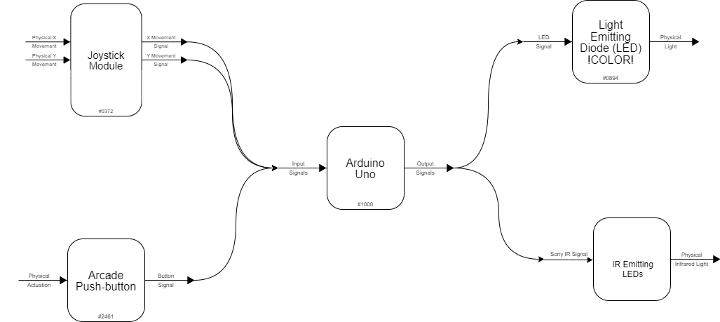
Our project is a TV remote that uses a joystick as the method of input rather than the traditional grid of small and soft buttons. First, we narrowed down the essential functions of the TV to a power button, volume up/down, and channel up/down. We mapped the volume up/down to the cardinal up/down directions on the joystick then mapped channel up/down to left/right on the joystick. We also enlarged the size of the power button to make it easier to push. These controls are processed and converted into IR wavelengths that matches that of Amy’s TV and broadcasted to the TV through an array of IR LEDs.
Final Product: Joystick Handle
Final Product: TV Control Box
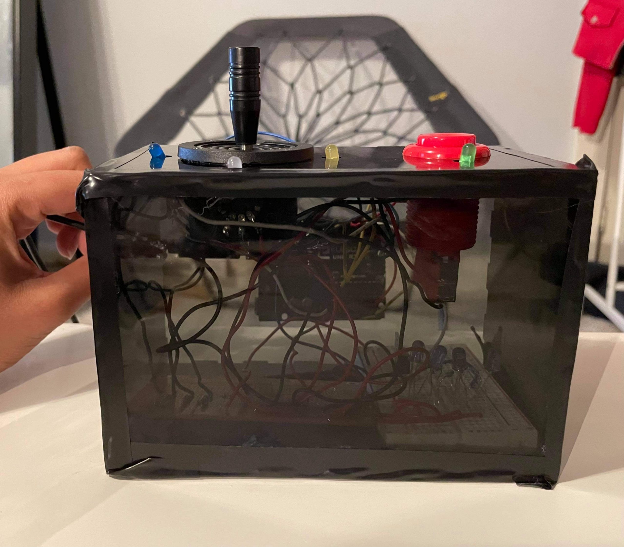
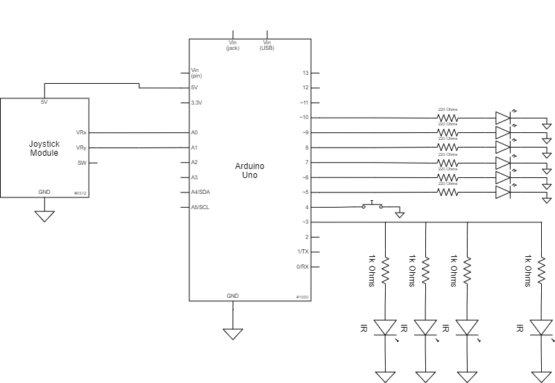
A view of the inside of the box, specifically showing the LED configuration (4 super bright IR LEDs in parallel with each other, each with 1000 ohms, and connected to the same MOSFET that connects to a pin on the Arduino.
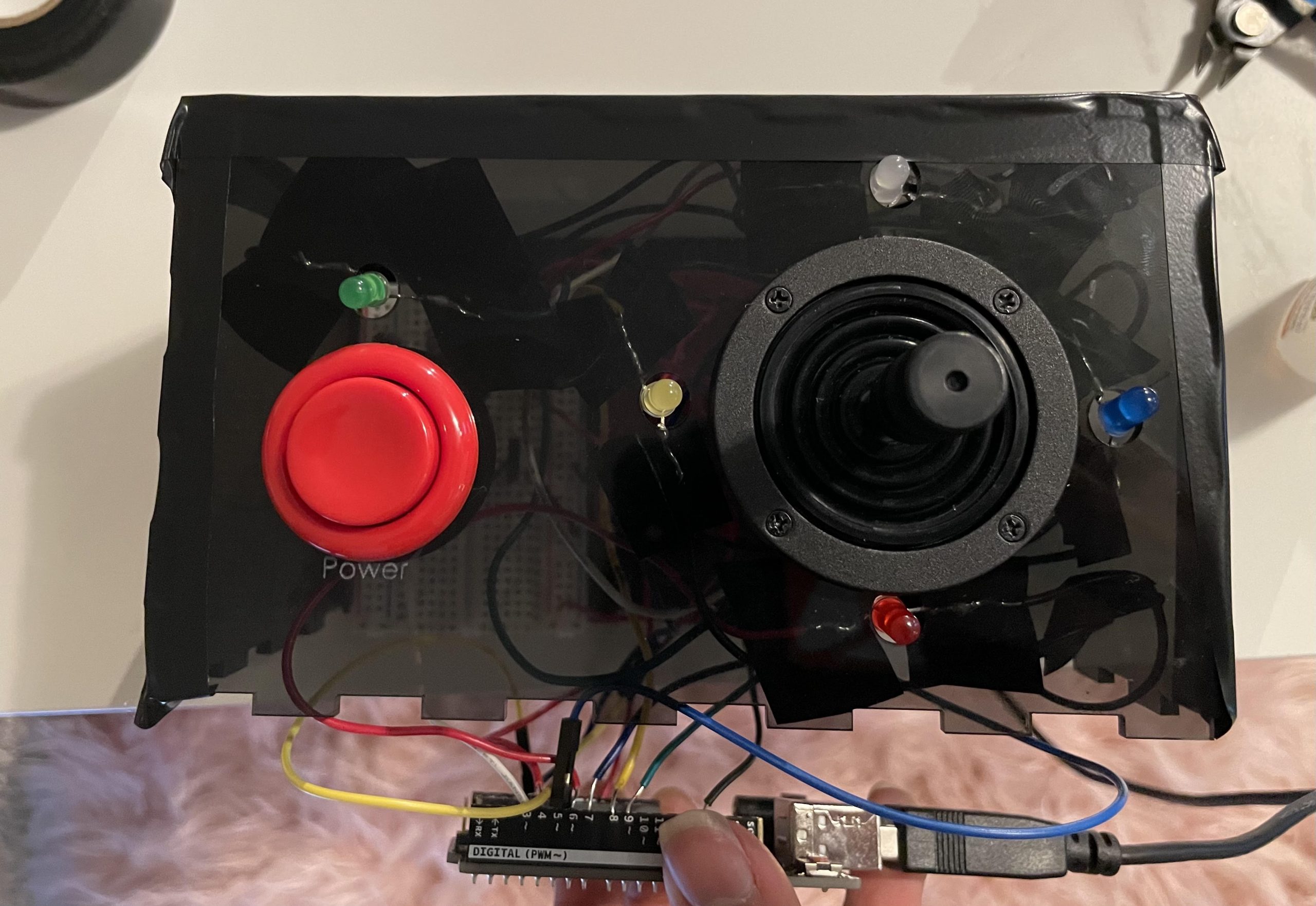
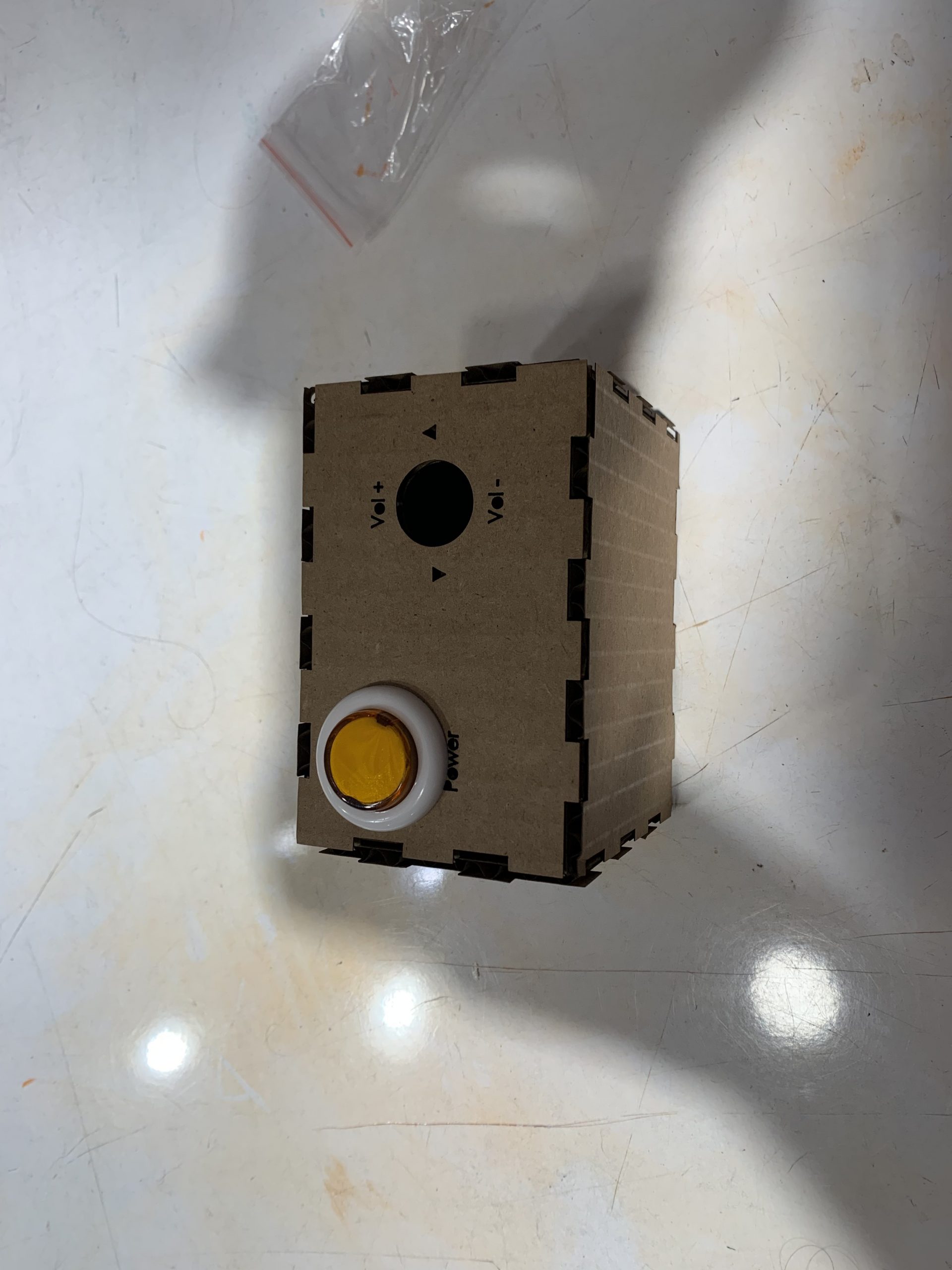
A top-view of the control box. The LEDs corresponding to different instructions can be seen here. These indicator LEDs show Amy what button was actually pressed, to make sure she knows whether she actually pressed the power button or accidentally changed the channel instead of the volume, in case her muscles don’t do exactly as she desires.
Unfortunately, we were not able to attach the joystick handle to the wiring of the final product because the parts for the joystick itself arrived too late. Ideally, we would quickly drill a hole in the bottom of the grip that fit the diameter of the joystick and find the optimal hole depth to provide stability but not bring the grip too close to the surface of the box.
Narrative
Amy gets home and is bored of browsing Facebook, so she decides to watch TV! Luckily, her new joystick actuated TV remote is here for her! Her father mounts it to her lapboard and she can use her TV without assistance! After watching a movie, she decides she wants to switch the channel to watch HGTV and moves the joystick to change the channel. Unfortunately the host’s voice on HGTV is quiet, but she can fix that by using the joystick to turn up the volume! Eventually she decides to stop watching television, so instead of having to ask for assistance like she normally would, Amy simply presses the power button and can enjoy the rest of her day.
3. How we got here (prototype and process):
Part 1: Joystick Form Development (Daniel Zhu)
Question: How can we optimize the form of the joystick itself to make it comfortable and easy for Amy to use?
During the interview we learned that Amy had limited movement in her arms due to muscle atrophy that she had developed over the years after her accident due to bedrest. To begin the prototyping process, I started by brainstorming a number of different shapes that focused of limiting the amount of work that Amy would need to do with different parts of her hand.
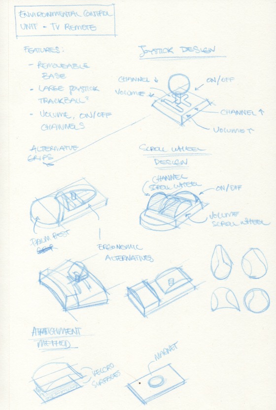
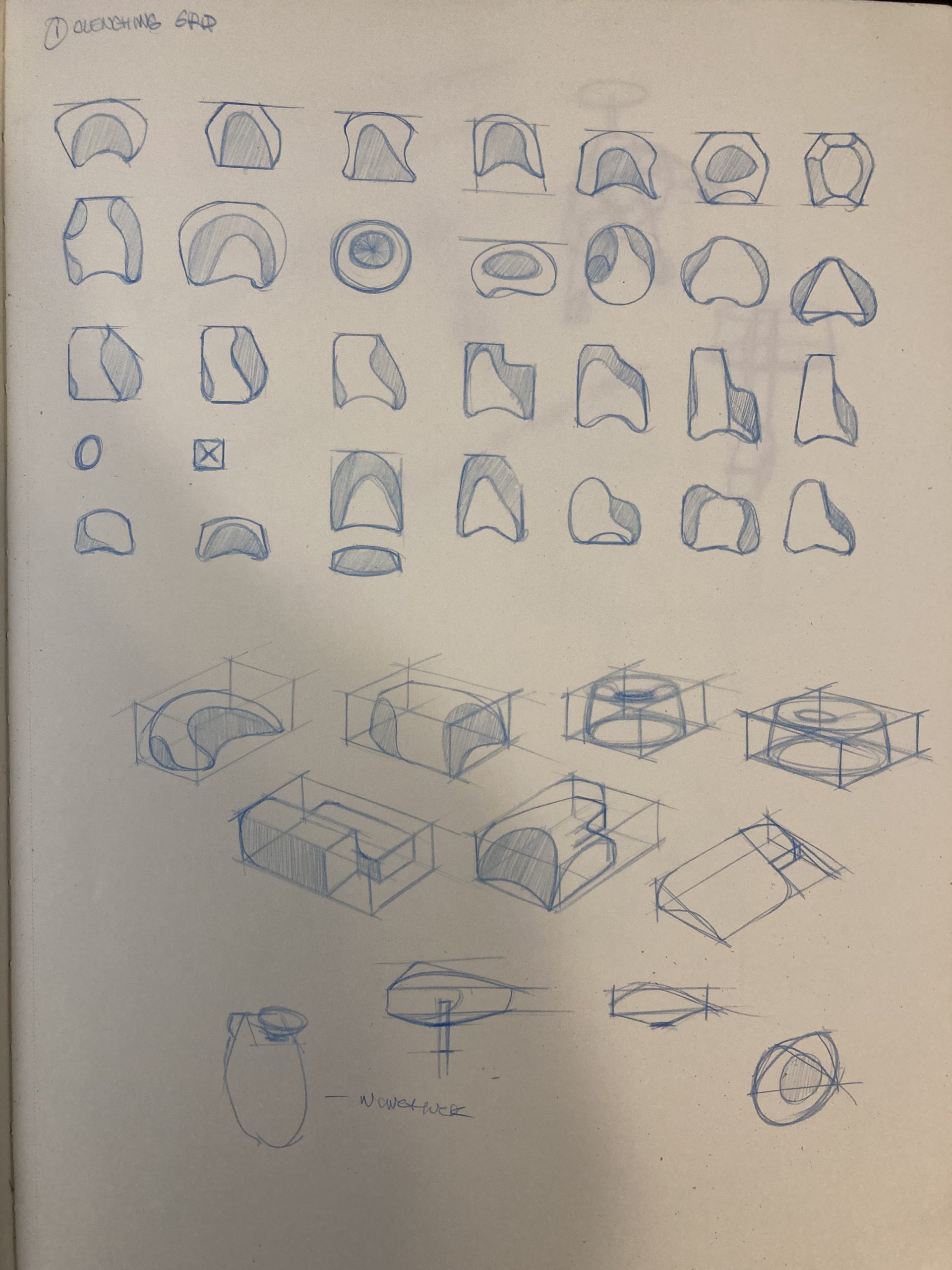 Each of the forms in these sketches focused on methods of gripping the joystick. At this point, I was thinking about how Amy’s posture sitting or laying down on the bed would affect her posture and the muscles she would use to move her arms, wrist, and hand against gravity and what support she would have in either situation from the bed or wheelchair. Eventually, I narrowed down these sketches to three broad approaches based on the part or arm or hand it demanded the most fine motor movement from. My plan was to present each of these approaches to Amy during our feedback session and further develop the one that she felt would best fit her needs.
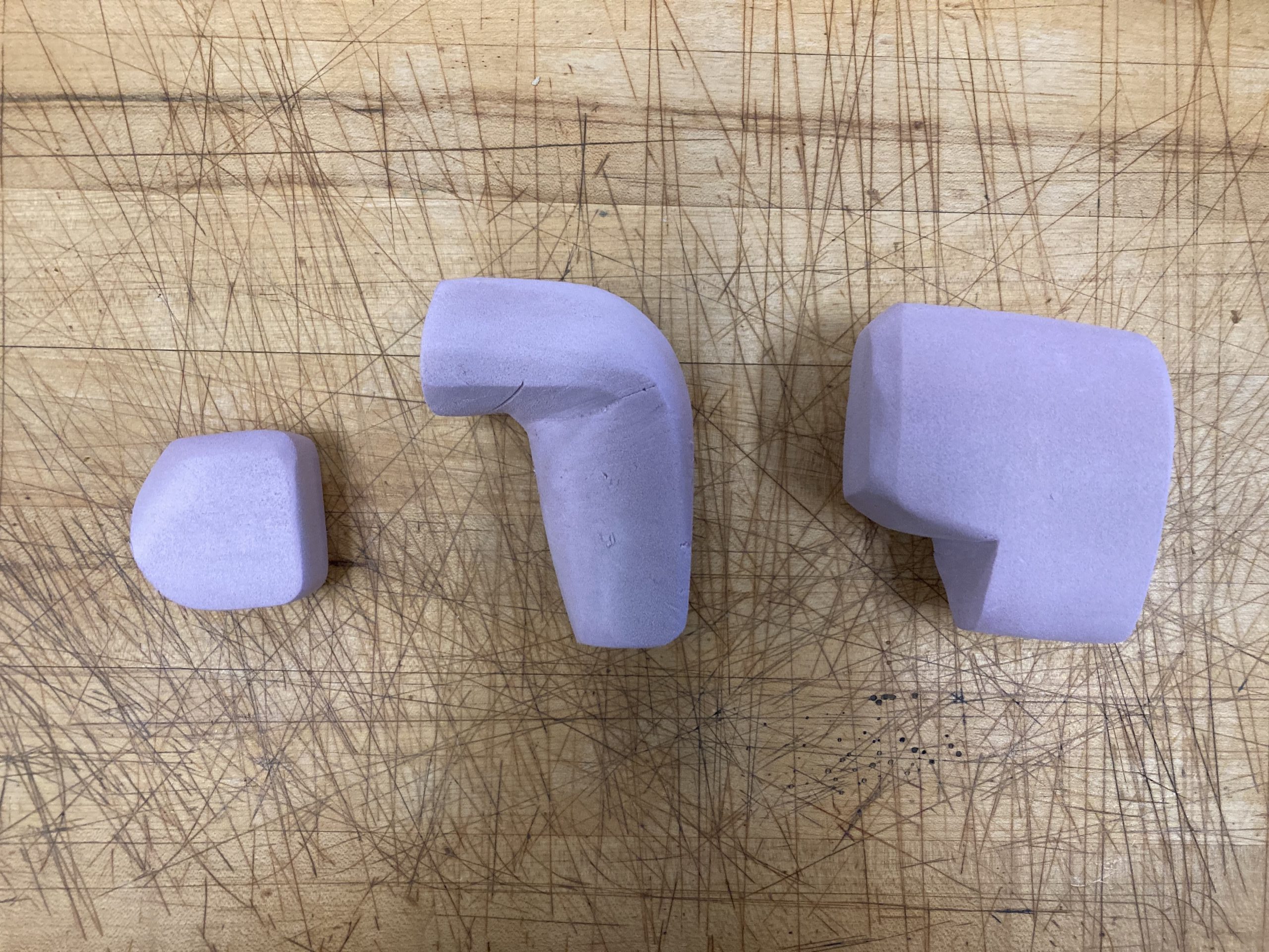
From left to right, the prototypes emphasized movement in the: fingers with the hand and palm static, the thumb and forefinger with everything else static, and the hand static with the wrist or arm providing movement. I tried to target parts of the arm and hand with a decreasing level of fine motor control required from left to right. I carved each of these prototypes from block of foam I cut in half then composited with wood glue. Detailed images of how each model is held are shown below:
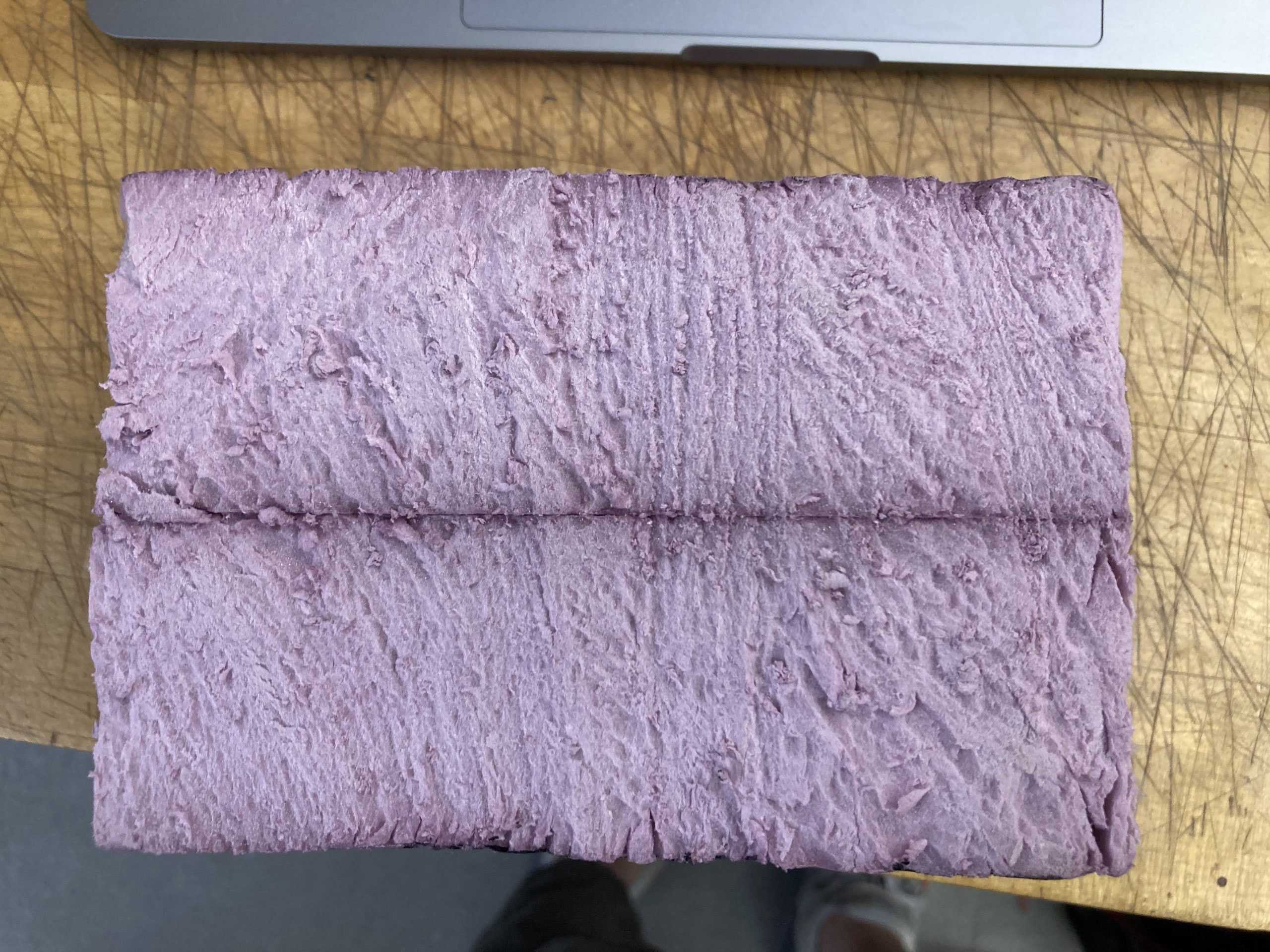
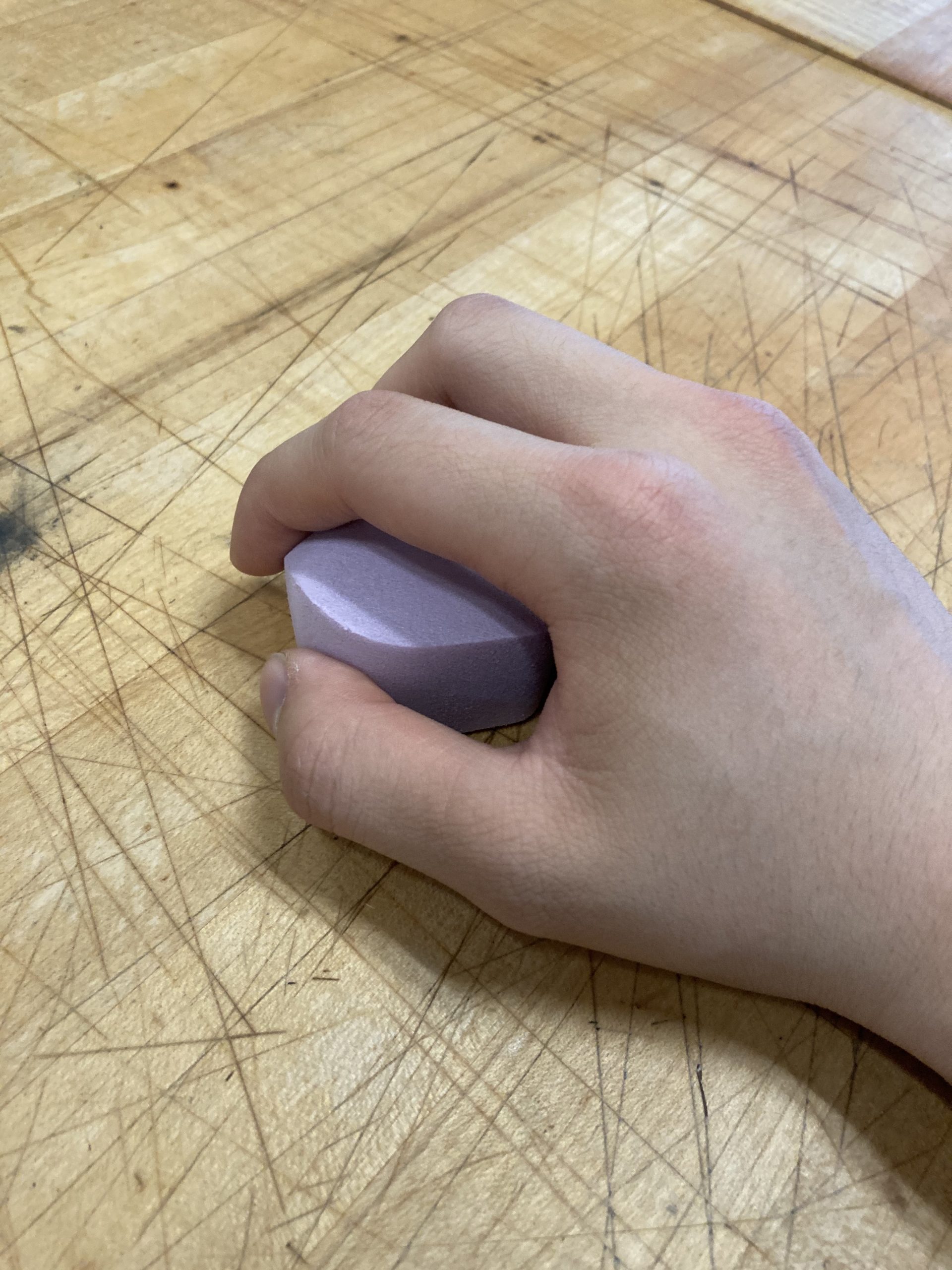
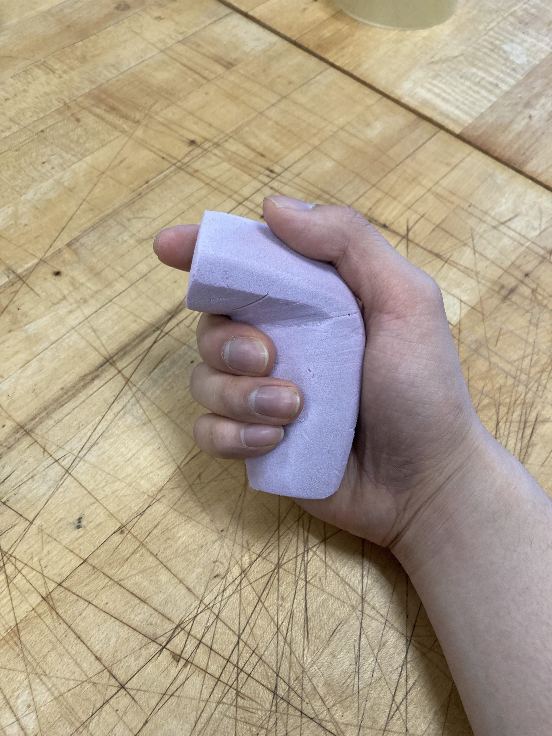
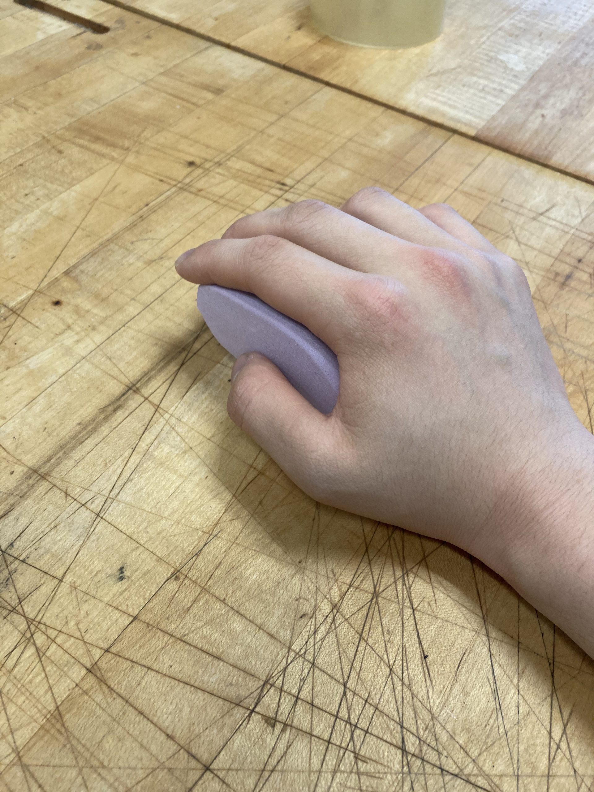
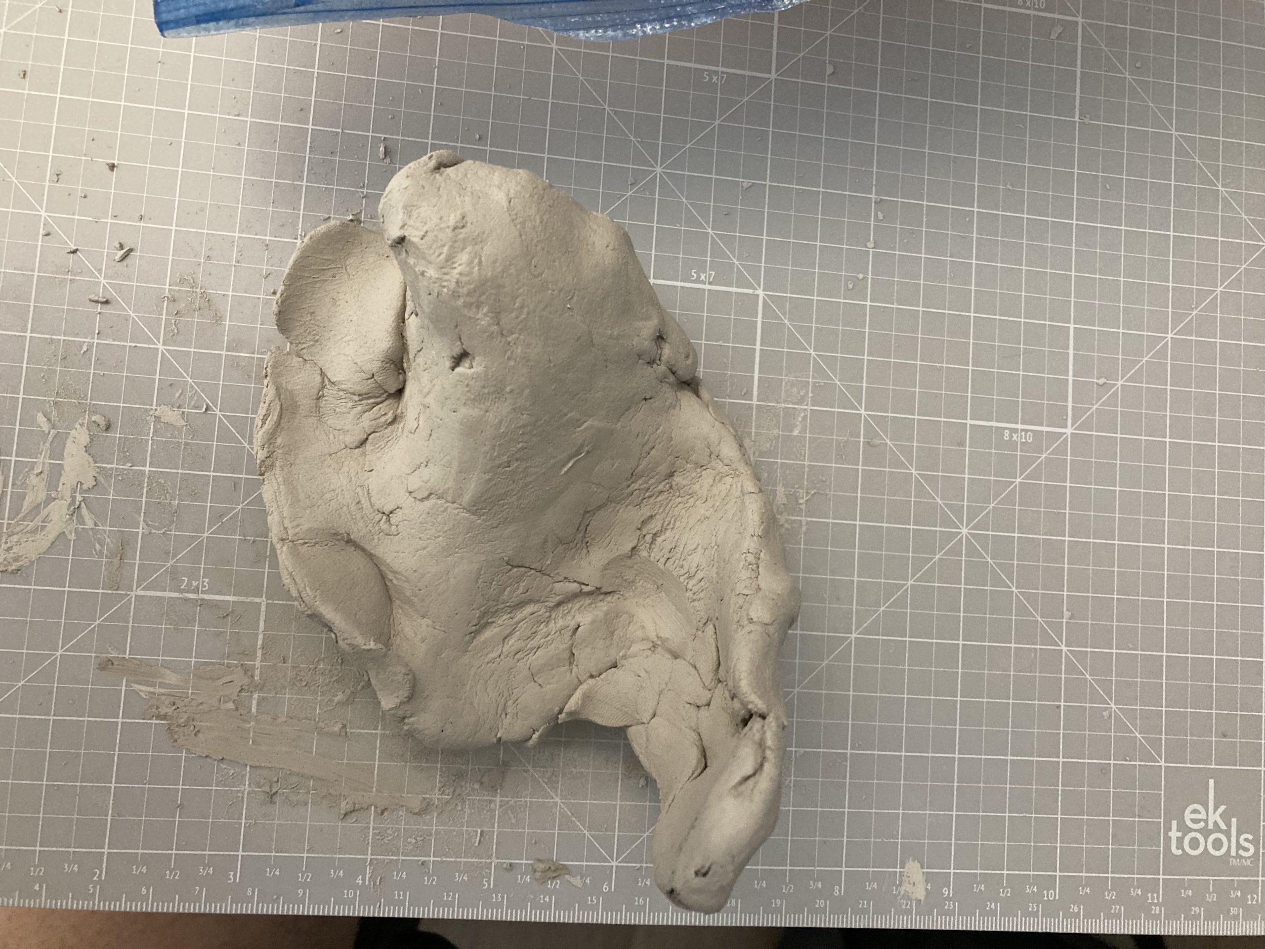
I also did additional rough exploration in clay to get an idea of how each grip would feel in hand before I fully fleshed out the idea in foam. I roughly shaped the clay into a shape approximating the grip to see how it would fit into my hand. The picture below shows one of such models I created to help me narrow down the forms of the three foam models I eventually made.
Prototype 2:
Question: How large should the enclosure be and how should we lay out the input devices to be most easy to use for Amy? In addition, how well would a scroll wheel input work versus a joystick?
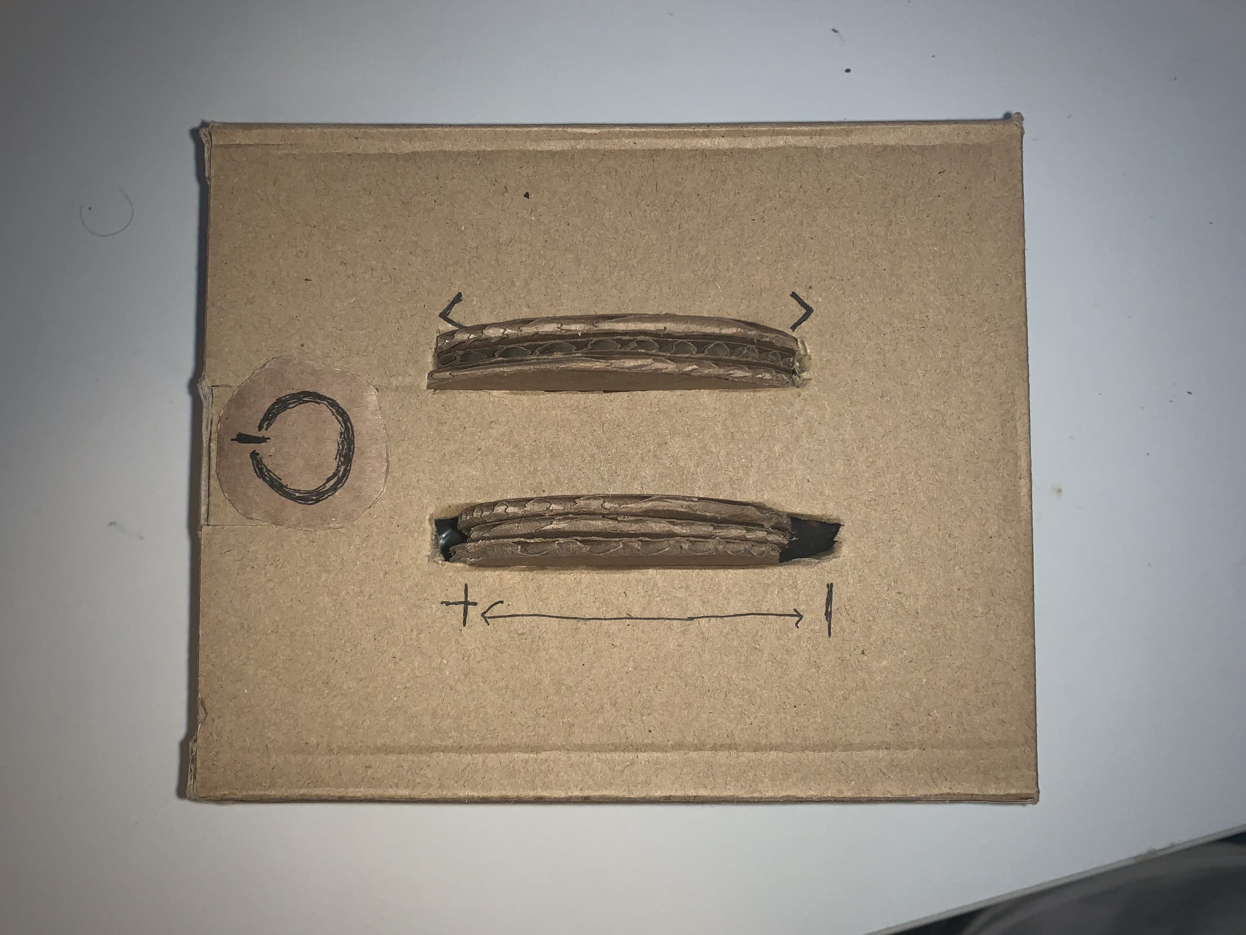
Prototype Enclosure
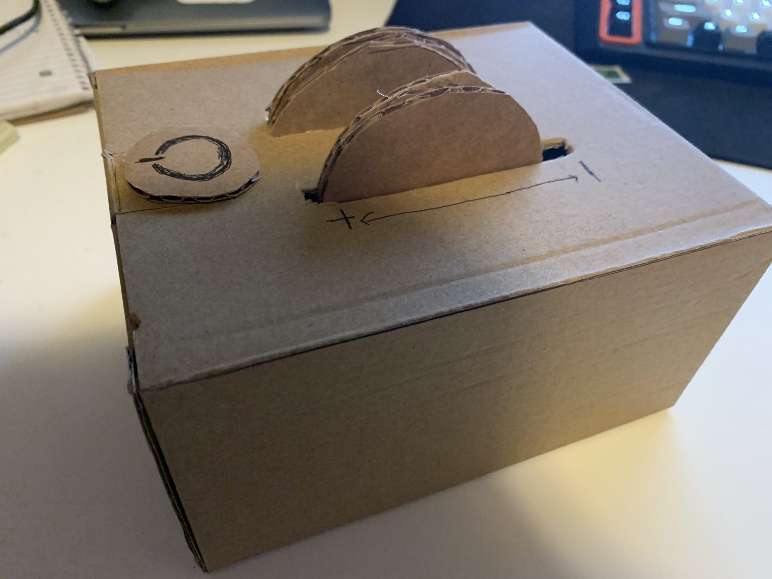
For the enclosure prototype, we used a cardboard box with mock scroll wheels and a power button to indicate what the layout would be for Amy so that we could get feedback on the design. During the prototype meeting, we got the valuable feedback that we needed about a hand-width between input devices to ensure that Amy wouldn’t accidentally press any buttons. We also decided against the scroll wheel as it would have required the device to be much wider since the input devices need to be very far apart, as well as more technically difficult to implement.
Prototype 3:
This prototype was designed to investigate how the IR LEDs should be designed to communicate between the box and the TV.
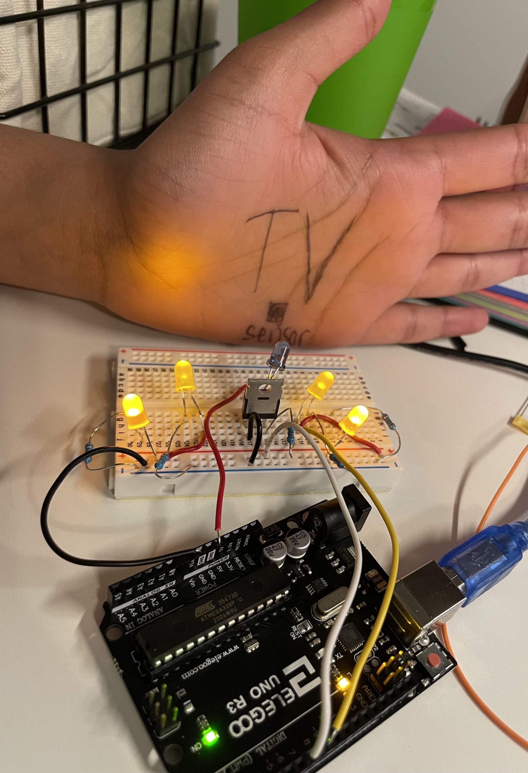
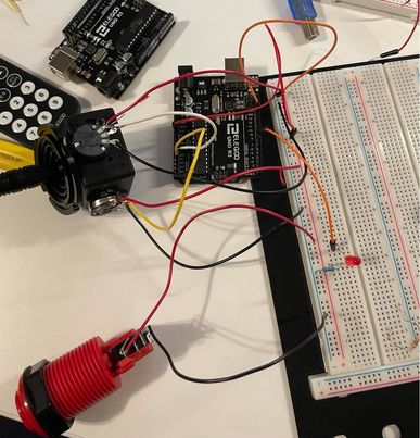
The first configuration here, with one IR LED pointing directly to the TV. I was able to test with an IR receiver that it was accurately positioned and had some leeway even if this apparatus got shifted slightly left, right, or backwards.
This is the second configuration. These would all be IR LEDs, powered by a MOSFET (this configuration was actually made first, so I had moved the MOSFET and actual IR LED to the other configuration, so it’s not featured in this picture).
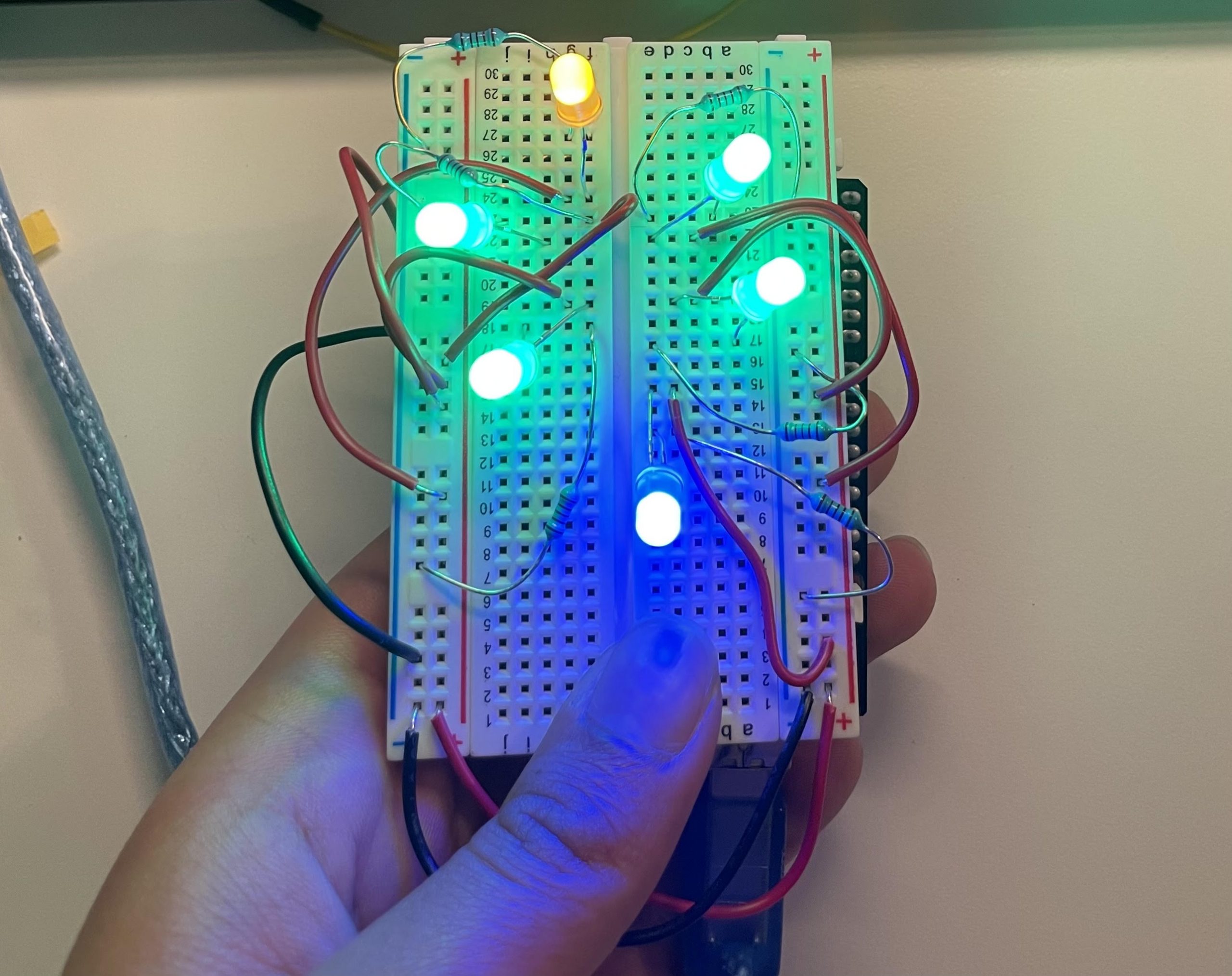
My prototype involved creating two mini configurations and comparing them. In the first one, the LEDs are aligned in a semi-circle, and would be stationary in front of the TV so that the IR signal would be aimed directly at the TV receiver at all times. In the second one, the LEDs are in a full circle and represent surrounding/moving with the joystick.
While designing the first configuration, we thought we could use a radio transmitter to get the signal from Amy to the IR LED, which would then translate and transmit the requested instruction to the TV, making sure it always hits the receiver. Since only 1 LED needs to be pointed to the TV, the other LEDs could be used to make sure the right request (power, channel up/down, volume up/down) was received by the IR, by flashing a corresponding color. In the second configuration, the IR LEDs are in a full-circle, to represent being attached to the joystick (shown in the ideation sketch). If Amy was moving around and the chair with the control box was facing different directions in the room, having the IR LEDs move with the joystick, and many of them, would make it more likely that the signal gets to the TV no matter what direction she’s facing. Since I only had one super bright IR LED, I had to make observations by using colored LEDs and seeing if there was any space where the color didn’t reach on the perimeter of my configuration when I moved the breadboard around. It would have been more helpful to be able to test this by using actual super bright IR LEDs and seeing if my IR receiver got the signal, and got the right signal, when the breadboard was being moved at different angles.
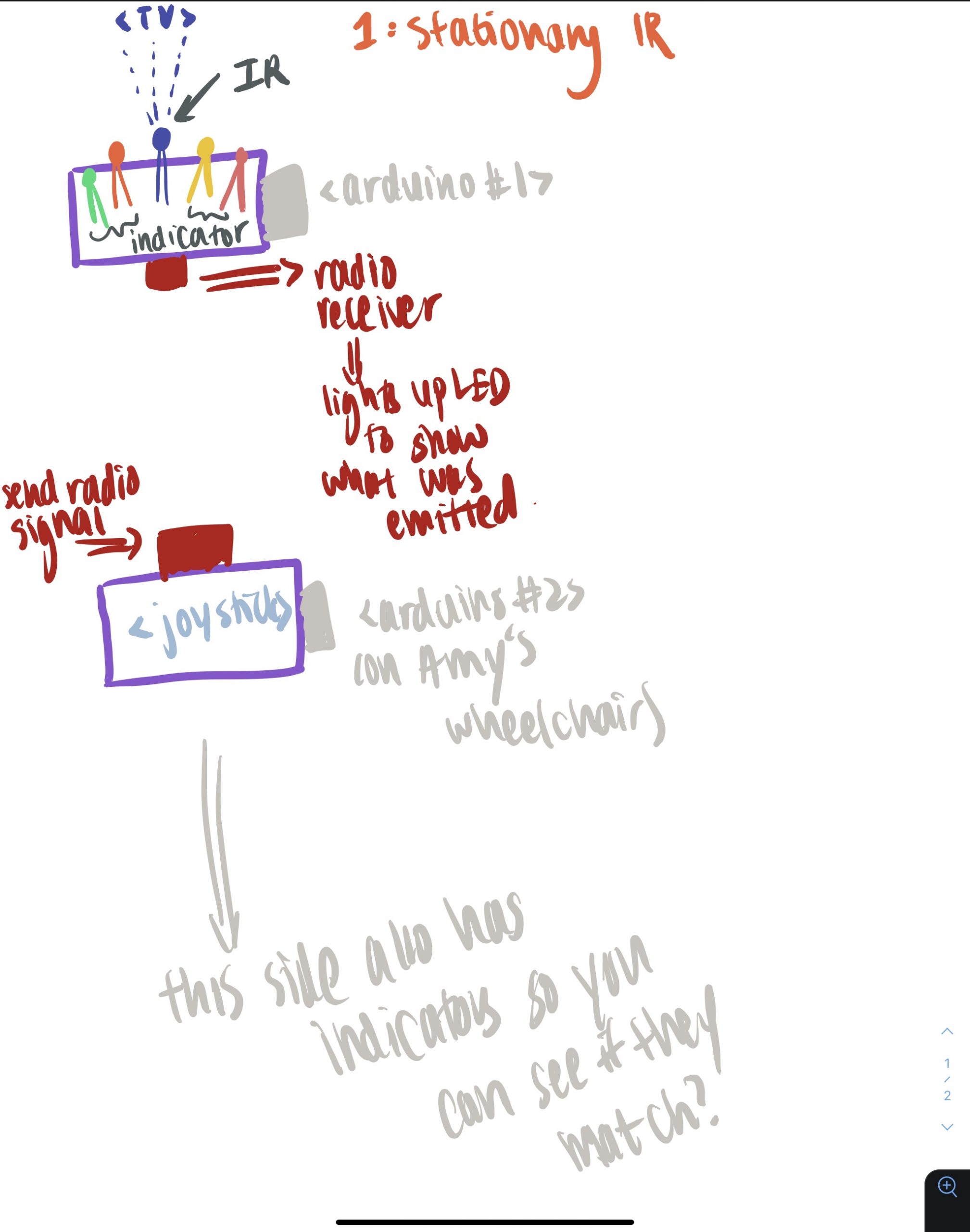
An ideation sketch for the first configuration. It would require two Arduinos, and also the radio module, if we were to pursue it. If were to use an IR receiver instead (another thing I considered), that would be stupid, because then we might as well send the IR signal directly to the TV, whereas a radio signal might be able to go further from any angle Amy faces.
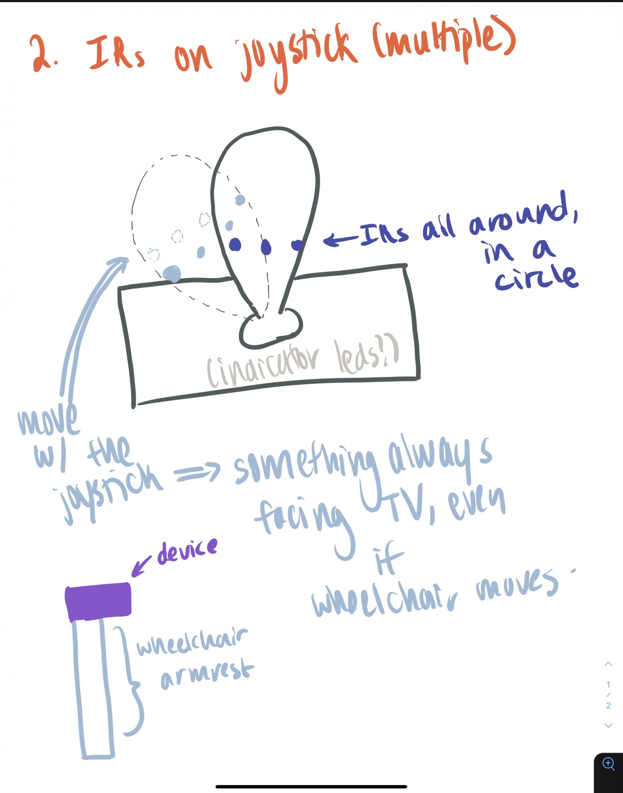
This sketch better shows how the LEDs would fit onto the joystick and move with the joystick. It would be more beneficial than using radio to get the instruction to an IR LED because two Arduinos would not be needed/supplied with power, making it easier to take care of in case something malfunctioned on either end of the sender/receiver in the previous configuration.
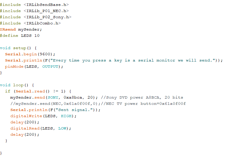
Simple code to make the IR led send a signal on demand so I could see how far it would transmit from. I also used an IR receiver to see the signal it was receiving. This code was adapting from the example IRLib2 code for “send.” I didn’t think much about whether we were using SONY or NEC at the time, so I experimented with both signals to see if they did anything different other than sending different numbers (they didn’t, although the Sony code seemed be received by the receiver more times than the NEC code).
- Your findings from the prototyping process. In essence—what was/were the answer(s) to your question(s)? Or if you didn’t find answers to your questions, then say so and explain what didn’t go to plan.
Although I couldn’t fully experiment with the IR LED configurations given that I only had one LED, by observing where the light falls and mimicking how the device would be used by rotating the board, I was able to come up with some conclusions. I observed that there was a tradeoff between consistency of the IR signal being received by the TV and from what angles Amy would be able to send the signals, as the second configuration’s transmitting signals wouldn’t necessarily always hit the receiver from *any* angle, but it allowed for more movement than if you only had one IR LED that always needed to face front. If we used the radio module with configuration 1, then perhaps this could be solved such that there’s both accuracy and range of motion, but the need for two Arduinos would be quite annoying for the user, especially if one dies or starts malfunctioning. I found this to be a problem throughout this processes when trying to emit signals from one Arduino and receive them from another, where sometimes the program would just stop running after a while. Also, the LED could send the exact same signal everytime, but if the IR receiver was facing different angles, it would sometimes receive different codes, which was odd. However, after speaking with Amy and asking her about how she moves around her, we learned that she’s pretty much always facing in the general direction of the TV when she’s in her wheelchair. Therefore, the IR LEDs don’t need to span a whole range of space and be in a circular configuration. Rather, if several of them face one general direction (forward), the signal should accurately reach the TV, without need for the radio module/second Arduino since we would be using super bright IR LEDs. Since Amy would be using a lap desk to place the TV controller on top of, the LEDs really wouldn’t need to be in a special configuration, as long as they could emit through the box. One type of positive feedback was the use of indicator lights as in configuration one. We decided to invoke this aspect in our final product, which also helped debug our final product a lot since we integrated the corresponding LEDs/colors while working and building the circuits.
Note: the configurations were disassembled and LEDs/resistors/Arduinos were reused in the final product and I didn’t save a video, but all that happened was the LEDs flashed when I typed in a letter to the Serial port. I also just moved around the breadboard as if it was on a joystick and made qualitative observations as best as I could, but you can’t see anything happening in that either.
Prototype to Process: Joystick (Daniel)
With these prototypes completed, we went in for the feedback session with Amy. During this feedback session, we learned that Amy not only had atrophied muscles but also was unable to move or feel anything below the elbow. On the one hand, this was a pretty big shock because we had somehow failed to learn this pretty critical factor during our first meeting. However, it also presented a good learning opportunity to correct that mistake by making sure we had clear picture of what she could and could not do for the final prototype. Luckily, while the first two prototypes were unusable, the prototype that involved keeping the hand static was similar to a product she already used and could be further developed. During the feedback session, Amy shared a link to an ergonomic joystick she already used for her wheelchair that worked well for her. Because this already was confirmed to work well for her, and we wouldn’t be able to test other designs with her in person before the final model, we decided to base the final joystick design off of the one she linked. Based on the design of the Panther joystick, I identified the key factors behind what made it work and created a few sketches to carve into a final wooden model:
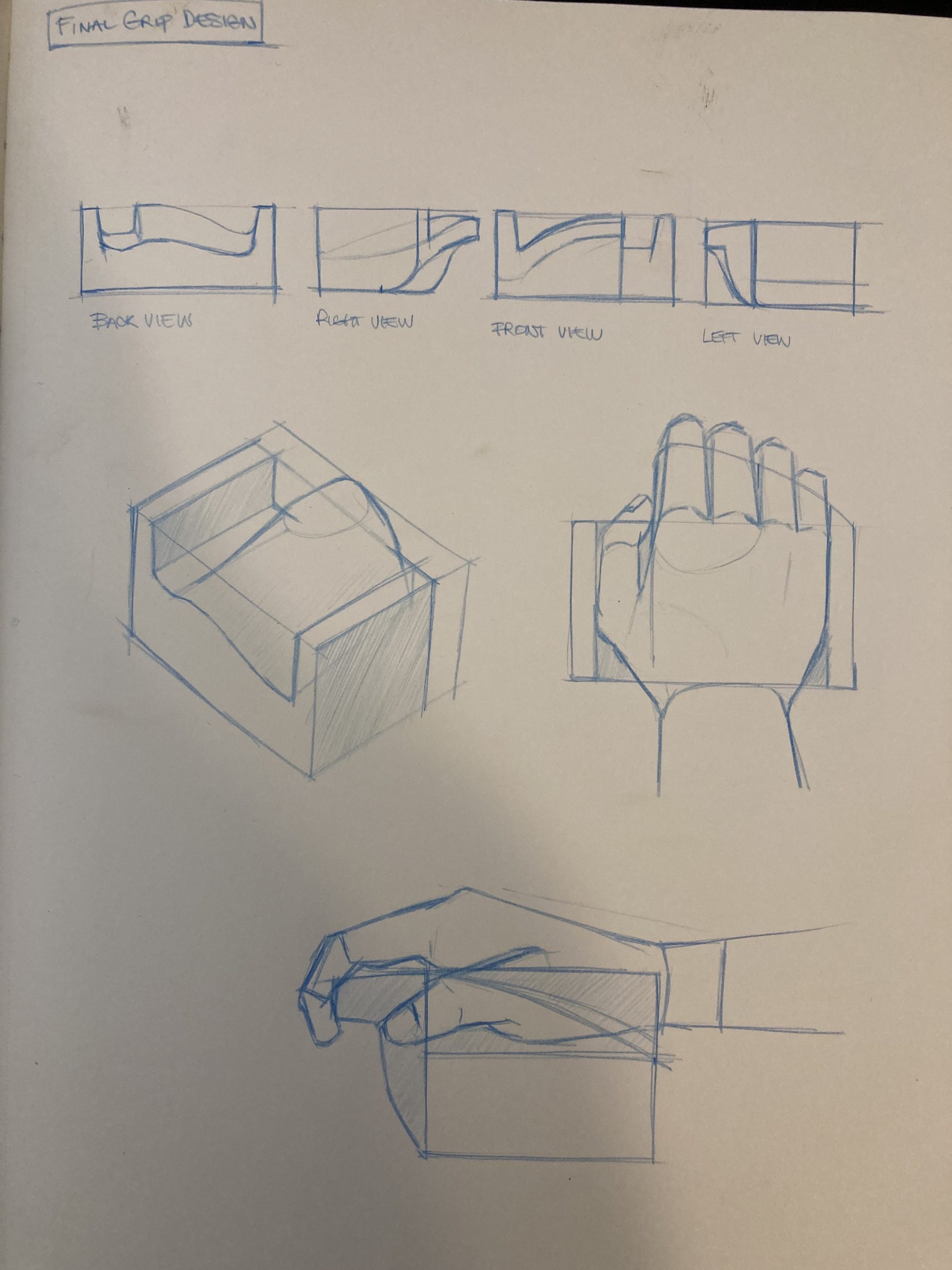
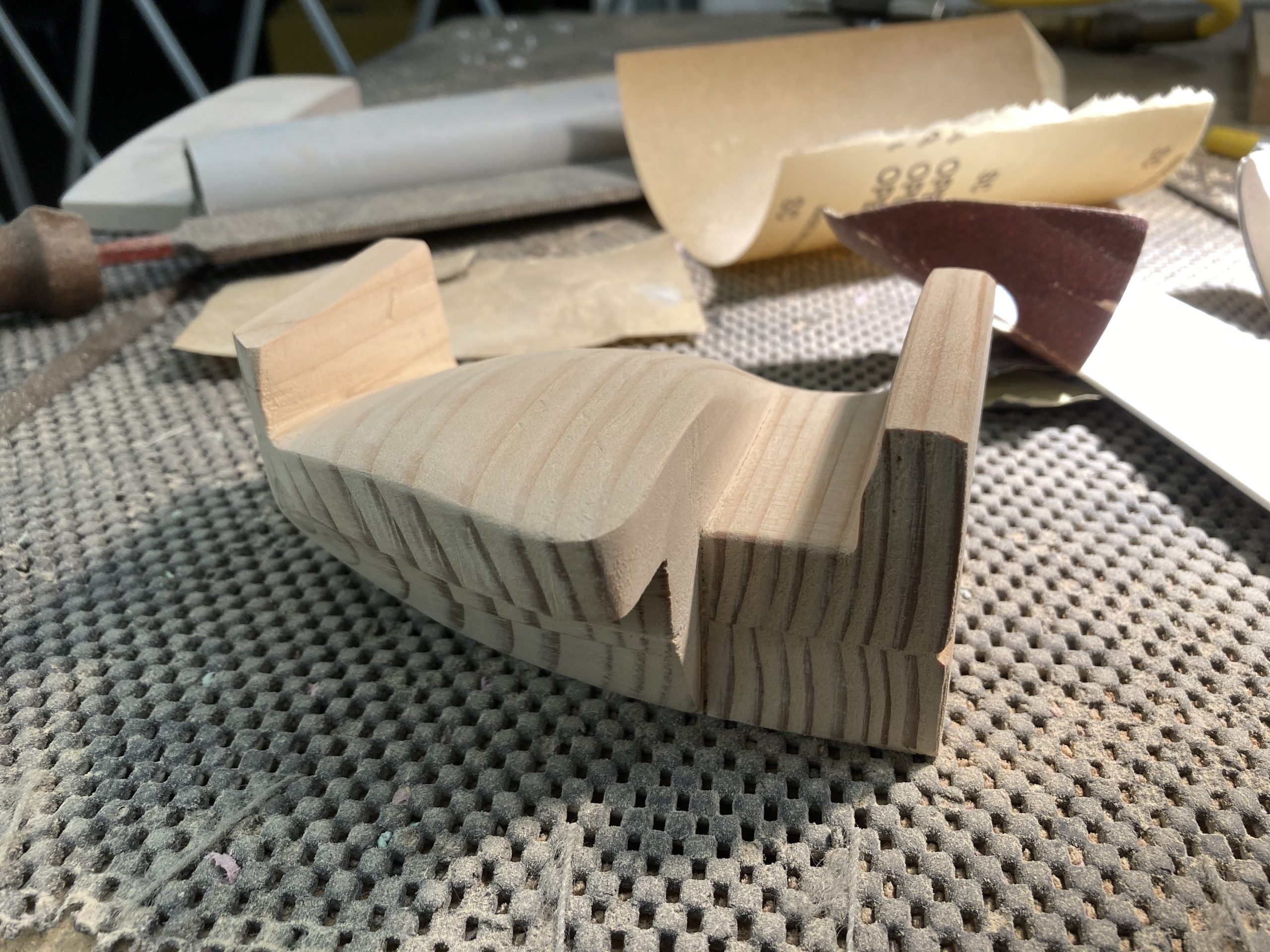
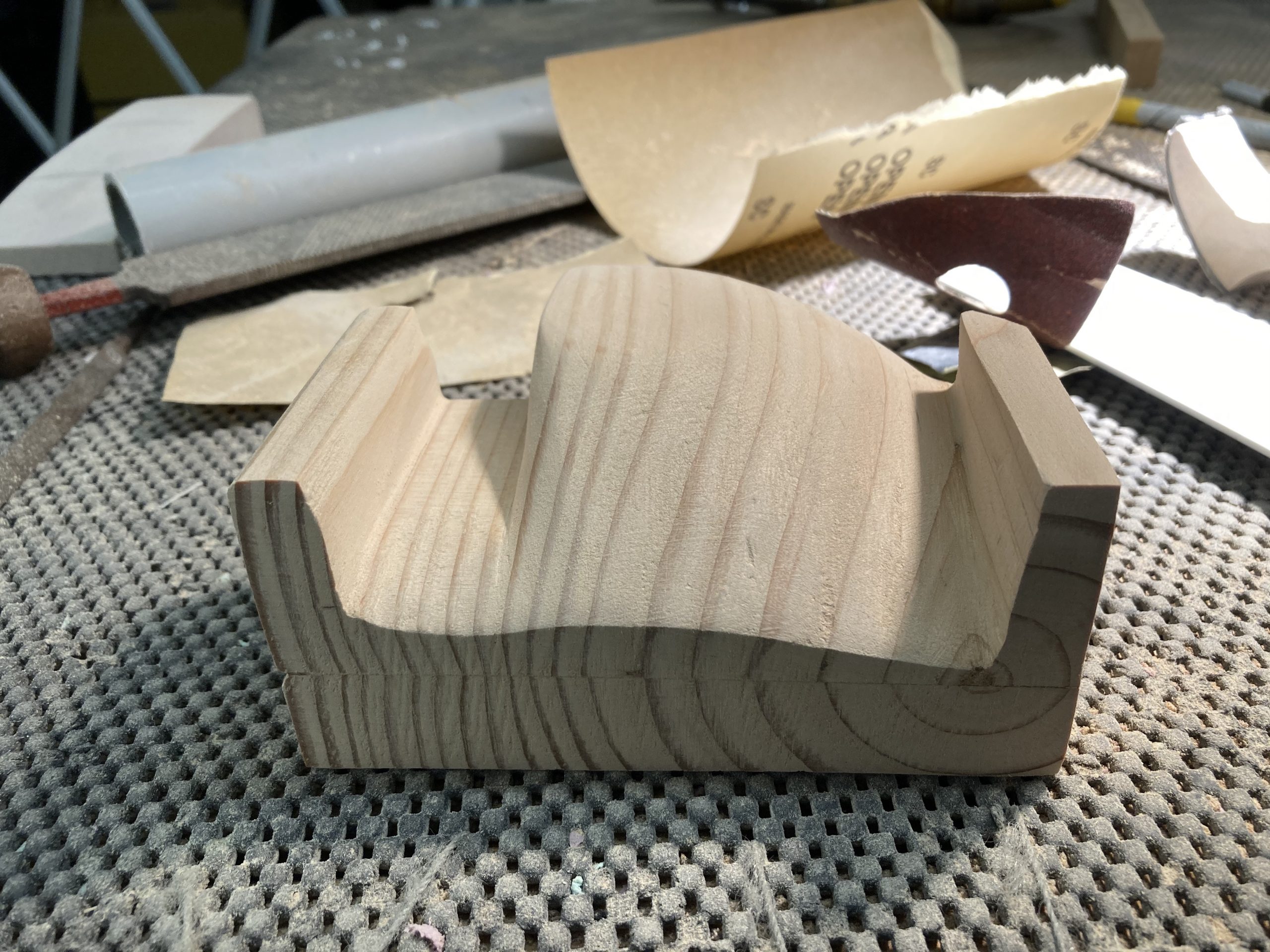
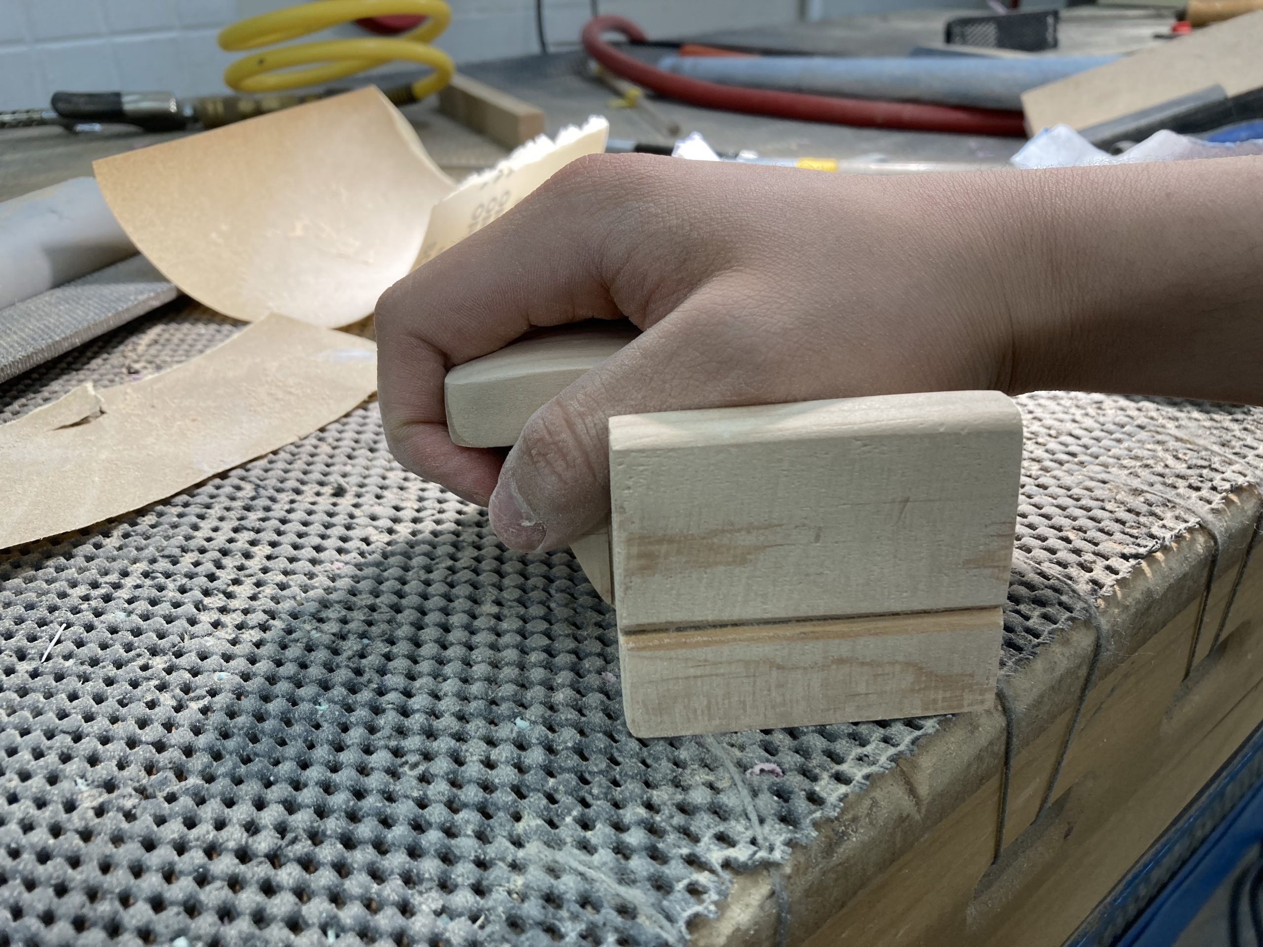
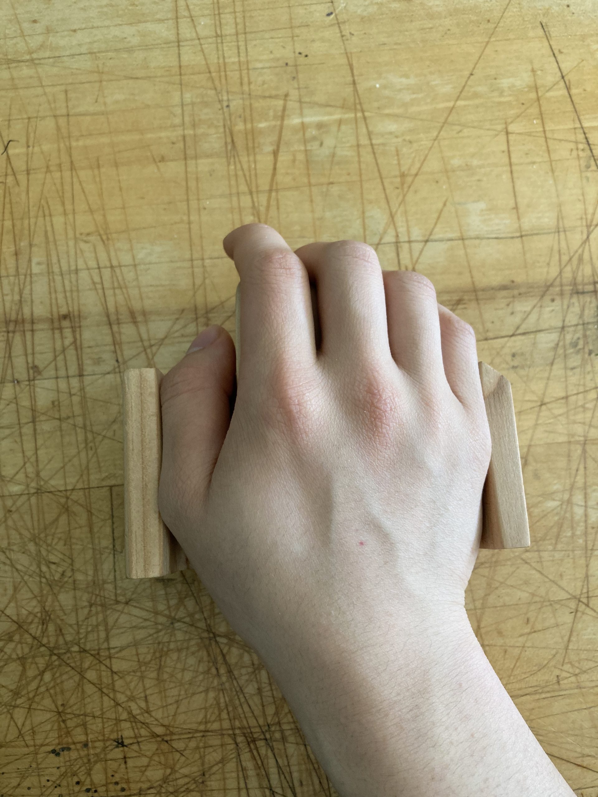
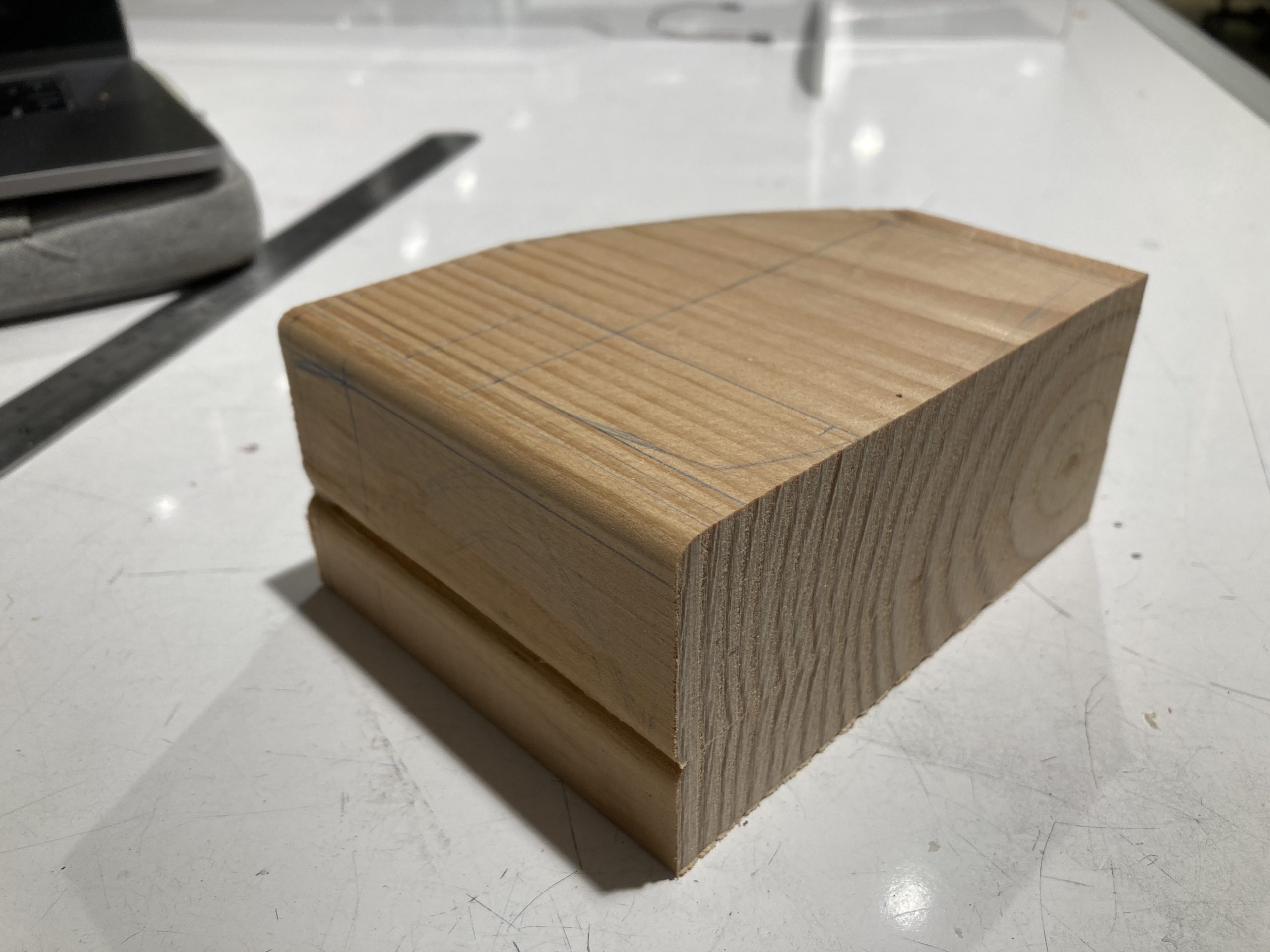
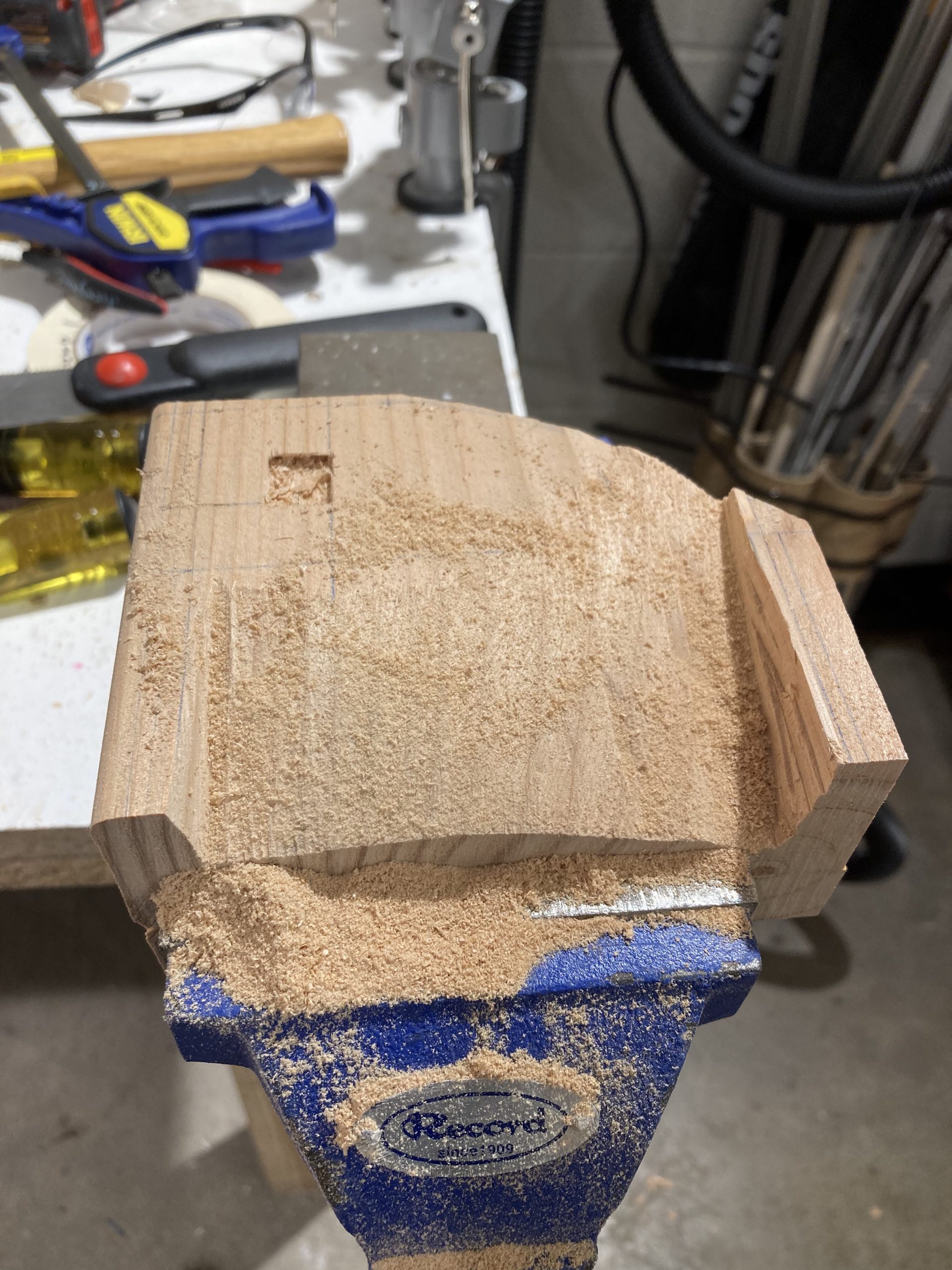
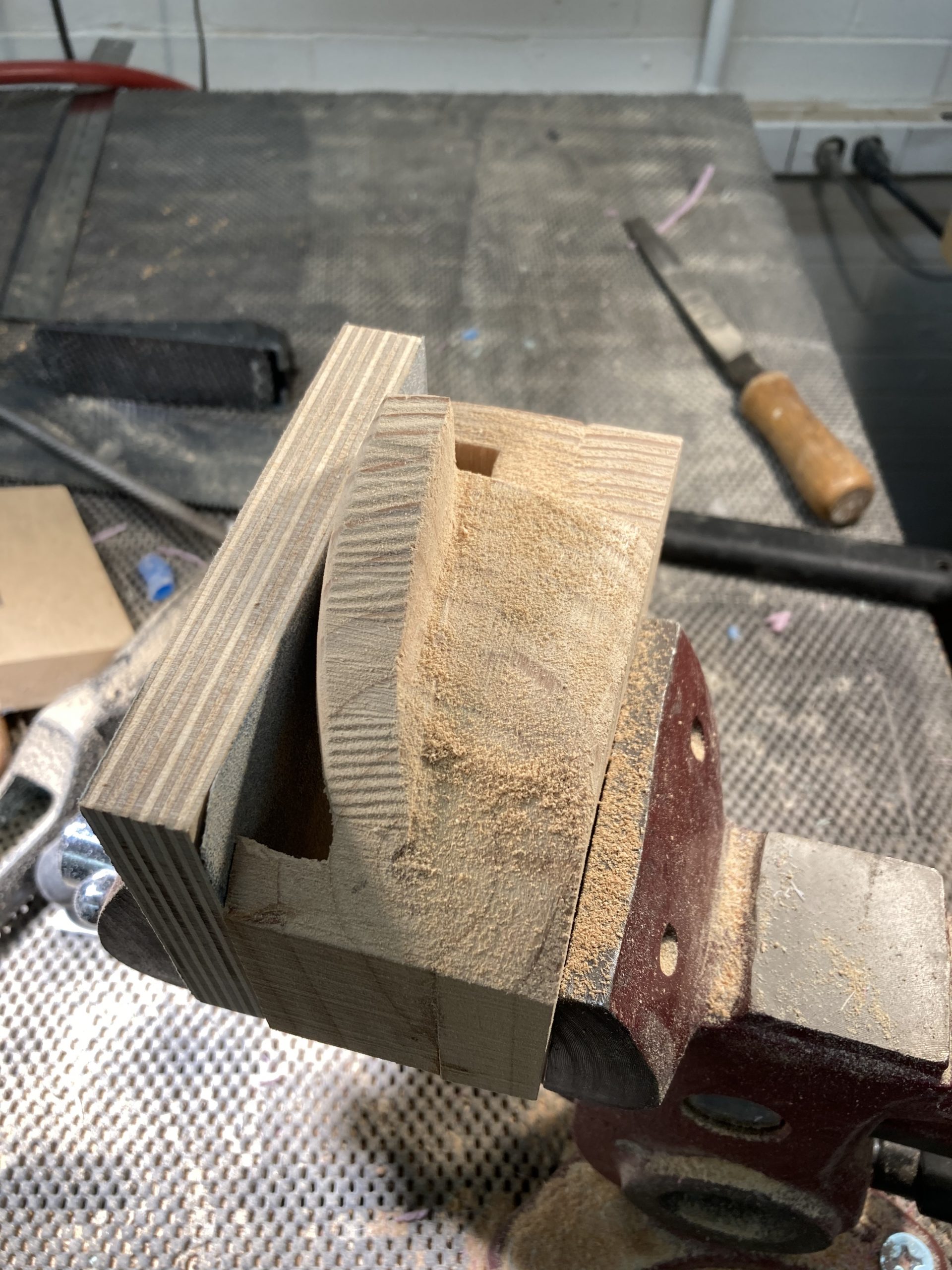
With the sketches complete and a set of measurements mapped out, I glued a piece of wood split in half together and carved out the final form, checking the ergonomics roughly against my own hand as a went while leaving space for tolerance to approximate how Amy’s hand might fit. I traced outlines of the form on the surface of the block before carving away or cutting with the band saw. Process pictures of the carving process are shown below:
Process of TV Box (Nish/Kevin)
We had several iterations of our enclosure, using the prototype enclosure as a baseline. The second iteration of our enclosure (above) was a learning experience for us. We thought the prototype was a little bulky, but after having the second iteration in hand, we realized it would be too small to meet the design requirements that inputs should be far enough apart that Amy could press buttons or move the joystick without a mistaken input.
Third/Final Enclosure
The final enclosure worked out great! It had sufficient spaces for all the electronics and was we intentionally made it with clear acrylic so that the IR signals could pass through the walls of the enclosure so it could control the TV. Due to the rushed timeline of putting together the box, it is functional but not fine-tuned. In the future, we would adjust the wires so that they are an appropriate length and all soldered into the protoboard, which would be attached to the box securely, and the LEDs would also be soldered into the base. Coverings on the LEDs would make the box more aesthetic. A more opaque material would have been preferred, but we found we needed this level of transparency for the IR LEDs to transmit accurately. Also, we would ideally have closed back and battery-powered Arduino, so that the box can be moved independently of being plugged into a computer.
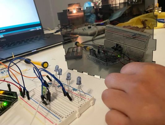
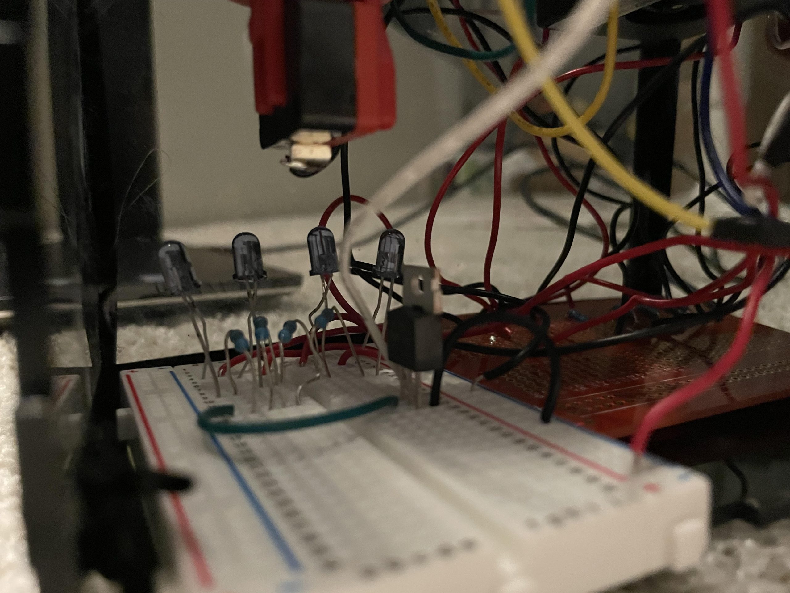
Here, we are testing the line up of LEDs to make sure the signal goes through our chosen material and that the signal is received correctly.
In this image, we tested the interaction between the button/joystick together, and making sure it lit up the LED when the joytick was pushed to the correct direction as in our code. I ran into some errors in this portion, finding that our joystick was coding oppositely to how we we wanted it to and not lighting up the right portion, and it turns out this was a mistake in the code where we were accidentally always calling the X parameters of the joystick instead of the Y parameters to test for channel up or down. Also, I was short-circuited the button for a while, and this caused the Arduino to malfunction for a while and I thought it was because it couldn’t take both the new joystick and the button at the same time, but that was not the issue. I repeatedly moved where the LED was plugged into, as well, in order to test for the different controls.
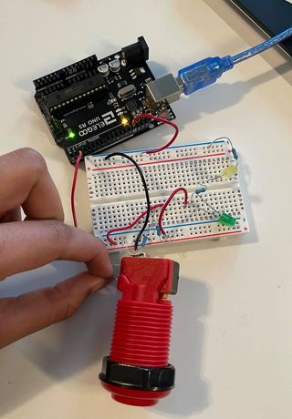
Even though this button was quite straightforward, I still tested it out to make sure it was working and that I wired it up correctly (always-on versus always-off), since this button has three prongs and I needed to ensure I was using the right ones. I ran into an issue where it was printing all 1s until held at a certain angle, and it turns out this was due to ground not being plugged in. I tested the button, once I fixed that issue, to make sure it was debounced in our code, and then tested it with the joystick.
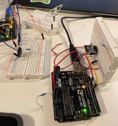
Here, I’m testing out the MOSFET with a smaller LED to make sure my wiring is correct and the signal is going through. I started with a smaller MOSFET from the Arduino kit and the regular IR LEDs, switched out and reconfigured the circuit with the bigger MOSFET once the smaller circuit was working. At this time, I wasn’t sure if we would be getting enough super bright LEDs for the project, and was confused as to why the one super bright LED I did have wasn’t working. After a couple of hours, it turns out that as previously described, I had plugged the power into ground :D. After figuring out the error, I then proceeded to add more LEDs (using the super bright ones now) and resistors in parallel, making sure to maintain a low enough overall resistance such that enough current still flows through the LED while also making sure I didn’t blow the LED (although I later learned that it was very unlikely I would blow the LED anyway).
What didn’t go to plan
In general, we didn’t run into any unexpected issues we were responsible for. Our circuit design and code seemed to work fine and we budgeted enough time to make several iterations to improve the design of our box. The main issue we ran into was that our parts order took a very long time to ship due to the lithium-ion battery we ordered. This was meant to be a nice feature for our project, as it would be rechargeable with a common USB cable, but because LiPo batteries need to be shipped by ground only all of the parts for our project including the joystick did not arrive until the day before our final presentation and demo. This made every part of our project more difficult as we were unable to test-fit any of our manufactured parts with the ordered parts and because of time constraints could not adapt our ergonomic joystick handle to the joystick. Another small issue we had was because we were unable to test-fit all of the components, the ergonomic joystick handle would have blocked some our indicator LEDs for when we activated volume up/down or channel up/down if we had time to attach it to the joystick as was noted in our final crit feedback. However, the light would still shine through and reflect enough to be seen even underneath the final handle apparatus.
4. Conclusions and lessons learned:
We received lots of feedback about our joystick handle, first and foremost: “The joystick handle seems really ergonomic,” and “The wooden joystick handle also adds a nice natural aesthetic to the whole device!” As seen above, the thought process and creation of the joystick handle was a huge part of our project, and it was a unique experience to model after someone’s discontinued product/something that Amy already owned, and produce that in a different material. A large reason that the handle “seems really ergonomic,” even in wood, was probably the emphasis on not only Amy’s resting position, but also that it requires no pressure from her fingers to pull the joystick back. It would have been really cool to actually get the handle on the controller and see if Amy could properly use it.
Someone brought up that the height of the box + the height of the handle may make it difficult for Amy to actually maneuver in real life if it’s sitting on top of her lap desk: “Does the added height of the box+joystick+handle hurt the ergonomics due to the higher arm position needed to manipulate it? Or would the box be mounted to a lower surface?” Indeed, looking back, Amy’s current joystick is set below her wheelchair so she doesn’t need to move her arm up in order to place it on the joystick. Although we specifically talked with Amy about putting the device on top of her lap desk, this definitely could have been a problem, and to solve it, we may need to create an entire extension that lets the box attach out of the side of her wheelchair so the handle is below her armrest level. In fact, throughout the process, we found that sometimes even items we did discuss with Amy sometimes didn’t tell the full story, or we were missing part of the picture with her disabilities. For example, even during the interview, although we asked directly what her disability was, we didn’t know she was paralyzed from the neck down until about halfway through, as she initially only mentioned the bed sores, which was most recent to her. This is interesting to note when working with people with disabilities, specifically people that have had them for a long time: in the same way we don’t realize small things a disabled person might not be able to do, they also may not realize that regular portions of the way they’ve been running their lives for years is different than us, and may require special consideration. Even when you think you’ve gotten a direct answer, it might not capture the full story or context because details that seem trivial to the client may be left out initially. It’s also not their job in this scenario to think of everything that’s viable, though. Even though Amy made many suggestions on possible ways to have the device, we could have done a better job of analyzing it from her perspective to see if her suggestions would still be viable after the necessary modifications (e.g. putting the device on the lap desk, but our device is much taller than her tracking ball). If we had perhaps done a fake run-through as if we were Amy using the box (if we were able to combine our box together, as neither part individually looked too big), we could have maybe caught something like this earlier in our process.
It was also noted that the indicator lights were helpful: “Love the light indicators, the little things make a big difference.” I was initially surprised that many people commented on its utility, as it was initially a component that seemed like “something extra” to add to our device. Instead, the feedback helped us realized that these small add-ons that initially seem trivial can actually be quite useful when designing for people with disabilities. It was a good lesson to use something that arose from our own debugging process (our need to see what was being pressed and sent) and see it through to the final product, since normally we may not have seen the need to add something like that because if we make a mistake pressing the wrong button, it’s really easy to just quickly move our fingers and undo our action. However, if every action requires an extreme movement which is not as easy to do (pushing a joystick all the way to the left or right), it’s difficult to know, when you do multiple movements, what was received correctly or not. There was also a concern regarding how the lights and LEDs would work together: “It seems like the handle is blocking the LEDs?” Although it seems like the furthest LED light woulodn’t be able to be seen when the handle was placed on top, we believed the light woud scatter enough that even if something is on top of it (but not touching, as the handle would hover above the light), the light could still be seen as the color would illuminate the bottom of the wood just enough to know if it’s on or off. Perhaps we could have made that furthest LED, on the side of the TV controller closest to the TV and farthest from Amy, a more intense color than white, so the light would show better. Or, we could have altered the box so the lights are all in a row facing Amy on the side closest to her, and still correspond to the same actions
We received several pieces of feedback verbally that were also helpful. For example, several people brought up that Amy’s arm sometimes has spasms, and if there was anything in place to make sure that the device isn’t knocked over. A rubberized mat was suggested, such that the acrylic box could properly sit atop her own lap desk. We were initially thinking about using Velcro for this purpose, but the rubberized bottom would perhaps be better as it allows the mat to be moved from the lap desk if Amy doesn’t want a Velcro attaching patch to always be taking up space. The TV controller would be knocked over if necessary so as to not prevent an emergency, but typically, the rubberized mat would stop it from just slipping around regularly. Further, we also realized we need to make the back panel, if we added it, able to open on a hinge so that someone could open the enclosure to fix anything or change the battery, which we had intended to include.
As touched on above, it was a little difficult working remotely with our client on this project. We had trouble initially understanding what her disability was, and it was slightly difficult for her to show us over Zoom precisely because of the disability where someone else would need to angle the laptop camera for us to see anything, which was not always very clear. Most importantly, we were never able to truly gauge Amy’s range of motion and strength to know what she could do in terms of range of motion and also strength. We still don’t know if this is a device she could continue to use for a while or if, even though she might have the range of motion to, she would get tired very quickly. I think we did a good job trying to overcome this by modeling our device after mechanisms she already had, such as the ergonomic design and asking her about her comfort with buttons/joysticks, but it would have been extremely helpful to test a range of motion in our prototype stage.
One of the biggest lessons that we learned from the experience was to make sure that we made as few assumptions as possible and made sure we confirmed everything with our client. During the first interview, when we were discussing the physical aspects of Amy’s disability, we followed a line of questioning where we asked about how it impacted her life. Through this part of the interview, we learned a lot about various anecdotes about her daily life, such as her schedule, how she moved around, what she needed help with, and so on. However, this approach ended up not being thorough enough, and we ended up missing a critical detail of her disability: that she was also paralyzed below her elbow. While, the variety of approaches we generated for the joystick handle ended up being broad enough to still develop into a usable product, we learned this major detail much later than we perhaps should have.
We also learned to overestimate the size you need in your enclosure, then scale down. We initially thought that the first prototype enclosure was larger than it needed to be, so we took off a few inches on each dimension of the box to save some space. This resulted in our second enclosure iteration being much smaller than it should have been, requiring a complete redesign.
5. Technical details:
Schematic and Block Diagram:
/*
   60-223, Project 3 (Firs): Joystick Actuated TV Remote for Amy
   Daniel Zhu (dszhu), Nish Nilakantan (anilakan), Kevin Bender (kbender1)
   time spent: ~50 hours

   Description: This code is for a project that uses a joystick and large pushbutton to actuate a high-power
   IR LED using an adaptive design met to fit the needs of our client Amy who is mostly paralyzed below her
   shoulders with limited use of her right hand


   Collaboration and sources:
   1) Our joystick design was inspired by the ergojoystick
      Panther
   Pin mapping:

   Arduino pin | type   | description
   ------------|--------|-------------
   A0           Input     Joystick X-axis pin
   A1           Input     Joystick Y-axis pin
   3            Output    IR LED Output
   4            Input     Power Button Input
   5            Output    Volume Up Indicator LED
   6            Output    Volume Down Indicator LED
   7            Output    Channel Up Indicator LED
   8            Output    Channel Down Indicator LED
   9            Output    Power Button Indicator LED
*/
#include <IRLibAll.h>

// Pin mappings (changeme)
const int JOYSTICKXPIN = A0;
const int JOYSTICKYPIN = A1;
const int IRLEDS = 3;
const int POWERBUTTON = 4;
const int VOLUPLED = 5;
const int VOLDOWNLED = 6;
const int CHANUPLED = 7;
const int CHANDOWNLED = 8;
const int POWERLED = 9;

IRsend mySender;
// ir codes for sony tv
const int POWER = 0xa90;
const int BITS = 12;
const int VOLUP = 0x490;
const int VOLDOWN = 0xc90;
const int CHANUP = 0x90;
const int CHANDOWN = 0x890;

// initialize state variables
int chanUpState = 0;
int chanDownState = 0;
int volUpState = 0;
int volDownState = 0;
int powerState = 0;

//initialize last state variables
int lastChanUpState = 0;
int lastChanDownState = 0;
int lastVolUpState = 0;
int lastVolDownState = 0;
int lastPowerState = 0;

//initialize debouncing timers
unsigned long lastChanUpDebounce = 0;
unsigned long lastChanDownDebounce = 0;
unsigned long lastVolUpDebounce = 0;
unsigned long lastVolDownDebounce = 0;
unsigned long lastPowerDebounce = 0;

const unsigned long DEBOUNCEDELAY = 50;
const unsigned long LEDTIME = 2000;

const int CHANUPTHRESH = -350;
const int CHANDOWNTHRESH = 350;
const int VOLUPTHRESH = 350;
const int VOLDOWNTHRESH = -350;

unsigned long chanUpLEDLimit = 0;
unsigned long chanDownLEDLimit = 0;
unsigned long volUpLEDLimit = 0;
unsigned long volDownLEDLimit = 0;
unsigned long powerLEDLimit = 0;

int getJoystickX() {
  return map(analogRead(JOYSTICKXPIN), 0, 1023, -512, 512);
}

int getJoystickY() {
  return map(analogRead(JOYSTICKYPIN), 0, 1023, -512, 512);
}

int isChanUp() { //less than -512
  return getJoystickX() < CHANUPTHRESH;
}

int isChanDown() { // greater than 512
  return getJoystickX() > CHANDOWNTHRESH;
}

int isVolUp() { // greater than 512
  return getJoystickY() > VOLUPTHRESH;
}

int isVolDown() { // less than -512
  return getJoystickY() < VOLDOWNTHRESH;
}


void setup() {
  // put your setup code here, to run once:
  pinMode(JOYSTICKXPIN, INPUT);
  pinMode(JOYSTICKYPIN, INPUT);
  pinMode(POWERBUTTON, INPUT_PULLUP);

  pinMode(IRLEDS, OUTPUT);
  pinMode(VOLUPLED, OUTPUT);
  pinMode(VOLDOWNLED, OUTPUT);
  pinMode(CHANUPLED, OUTPUT);
  pinMode(CHANDOWNLED, OUTPUT);

  Serial.begin(9600);

}

void loop() {
  // put your main code here, to run repeatedly:
  int power = digitalRead(POWERBUTTON);
  int chanUp = isChanUp();
  int chanDown = isChanDown();
  int volDown = isVolDown();
  int volUp = isVolUp();


  //Serial.println("Y: %d \n X: %d", getJoystickY(), getJoystickX());
  Serial.print("Y: "); Serial.print(getJoystickY()); Serial.print(" X: "); Serial.println(getJoystickX());
  if (lastVolUpState != volUp) {
    lastVolUpDebounce = millis();
  }
  if (lastVolDownState != volDown) {
    lastVolDownDebounce = millis();
  }
  if (lastChanUpState != chanUp) {
    lastChanUpDebounce = millis();
  }
  if (lastChanDownState != chanDown) {
    lastChanDownDebounce = millis();
  }
  if (lastPowerState != power) {
    lastPowerDebounce = millis();
  }


  //check if button state changed and act accordingly
  unsigned long curTime = millis();
  if (curTime - lastVolUpDebounce > DEBOUNCEDELAY) {
    if (volUp != volUpState) {
      volUpState = volUp;
      if (!volUpState) {
        mySender.send(SONY, VOLUP, BITS);
        digitalWrite(VOLUPLED, HIGH);
        volUpLEDLimit = curTime + LEDTIME;
      }
    }
  }
  lastVolUpState = volUp;

  if (curTime - lastVolDownDebounce > DEBOUNCEDELAY) {
    if (volDown != volDownState) {
      volDownState = volDown;
      if (!volDownState) {
        mySender.send(SONY, VOLDOWN, BITS);
        digitalWrite(VOLDOWNLED, HIGH);
        volDownLEDLimit = curTime + LEDTIME;
      }
    }
  }
  lastVolDownState = volDown;

  if (curTime - lastChanUpDebounce > DEBOUNCEDELAY) {
    if (chanUp != chanUpState) {
      chanUpState = chanUp;
      if (!chanUpState) {
        mySender.send(SONY, CHANUP, BITS);
        digitalWrite(CHANUPLED, HIGH);
        chanUpLEDLimit = curTime + LEDTIME;
      }
    }
  }
  lastChanUpState = chanUp;

  if (curTime - lastChanDownDebounce > DEBOUNCEDELAY) {
    if (chanDown != chanDownState) {
      chanDownState = chanDown;
      if (!chanDownState) {
        mySender.send(SONY, CHANDOWN, BITS);
        digitalWrite(CHANDOWNLED, HIGH);
        chanDownLEDLimit = curTime + LEDTIME;
      }
    }
  }
  lastChanDownState = chanDown;

  if (curTime - lastPowerDebounce > DEBOUNCEDELAY) {
    if (power != powerState) {
      powerState = power;
      if (!powerState) {
        mySender.send(SONY, POWER, BITS);
        digitalWrite(POWERLED, HIGH);
        powerLEDLimit = curTime + LEDTIME;
      }
    }
  }
  lastPowerState = power;


  //turn off LED based on timer set
  if (curTime > chanUpLEDLimit) {
    digitalWrite(CHANUPLED, LOW);
  }
  if (curTime > chanDownLEDLimit) {
    digitalWrite(CHANDOWNLED, LOW);
  }
  if (curTime > volUpLEDLimit) {
    digitalWrite(VOLUPLED, LOW);
  }
  if (curTime > volDownLEDLimit) {
    digitalWrite(VOLDOWNLED, LOW);
  }
  if (curTime > powerLEDLimit) {
    digitalWrite(POWERLED, LOW);
  }
}
Solidworks Files
https://drive.google.com/drive/folders/1fAkqj0hCjyJDRPstvaO8WQSeJH48L45u?usp=sharing