
By: Nicole Yu
Overview
Description:
A remote controlled device that switches the light on and off from anywhere in the room.
Device In Motion:
The user is turning the light on and off far away from the light switch.
Here, you can see how the device’s pulley moves the plate up and down to flip the switch. The plate also centers itself after, allowing the user to flip the switch without the remote.
Overall Photo:
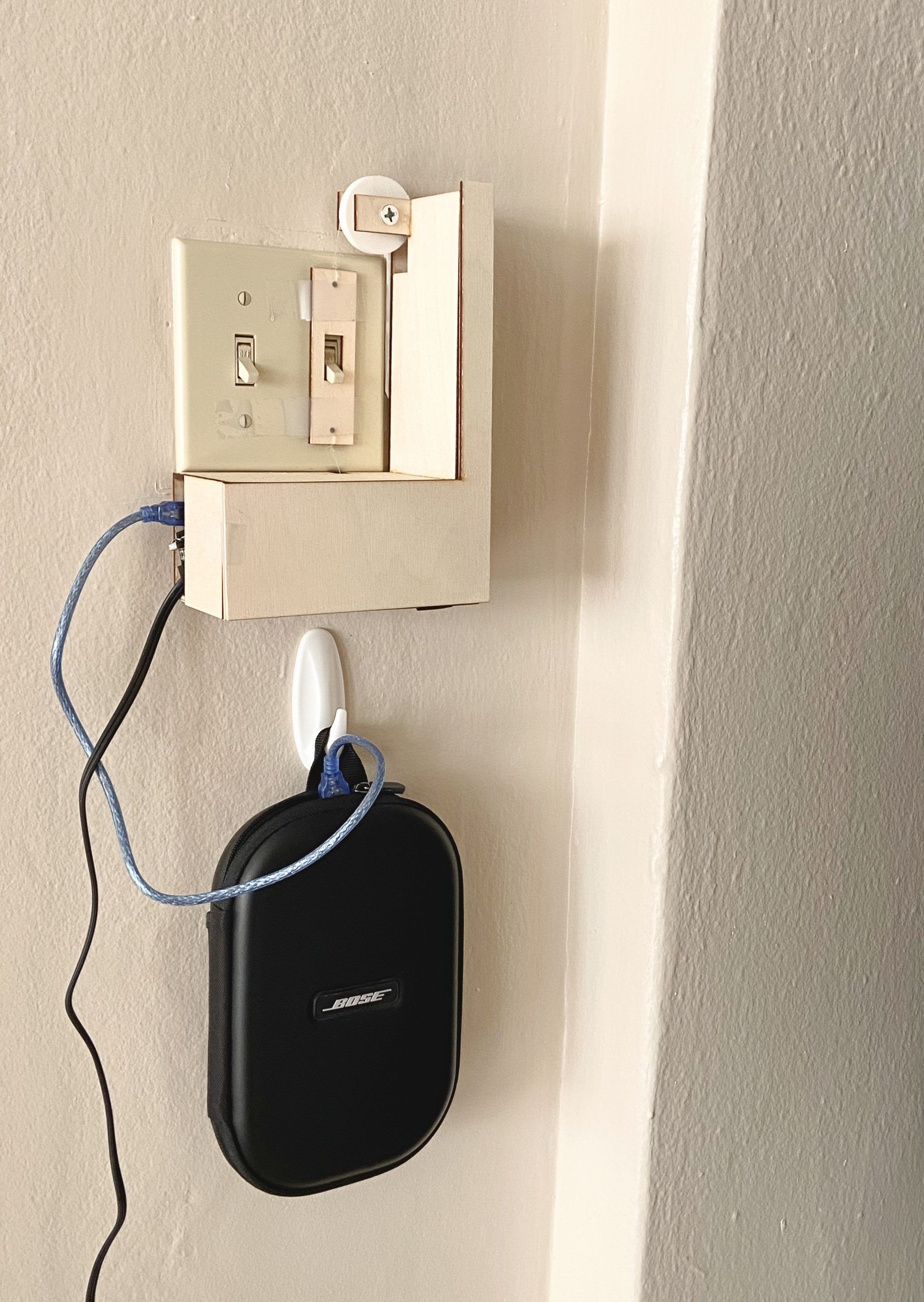
This is the whole device. Due to the short cable, I put the battery to the device in a case and hung it on the wall. The rest of the mechanism is inside the wooden case.
Detail Photos:
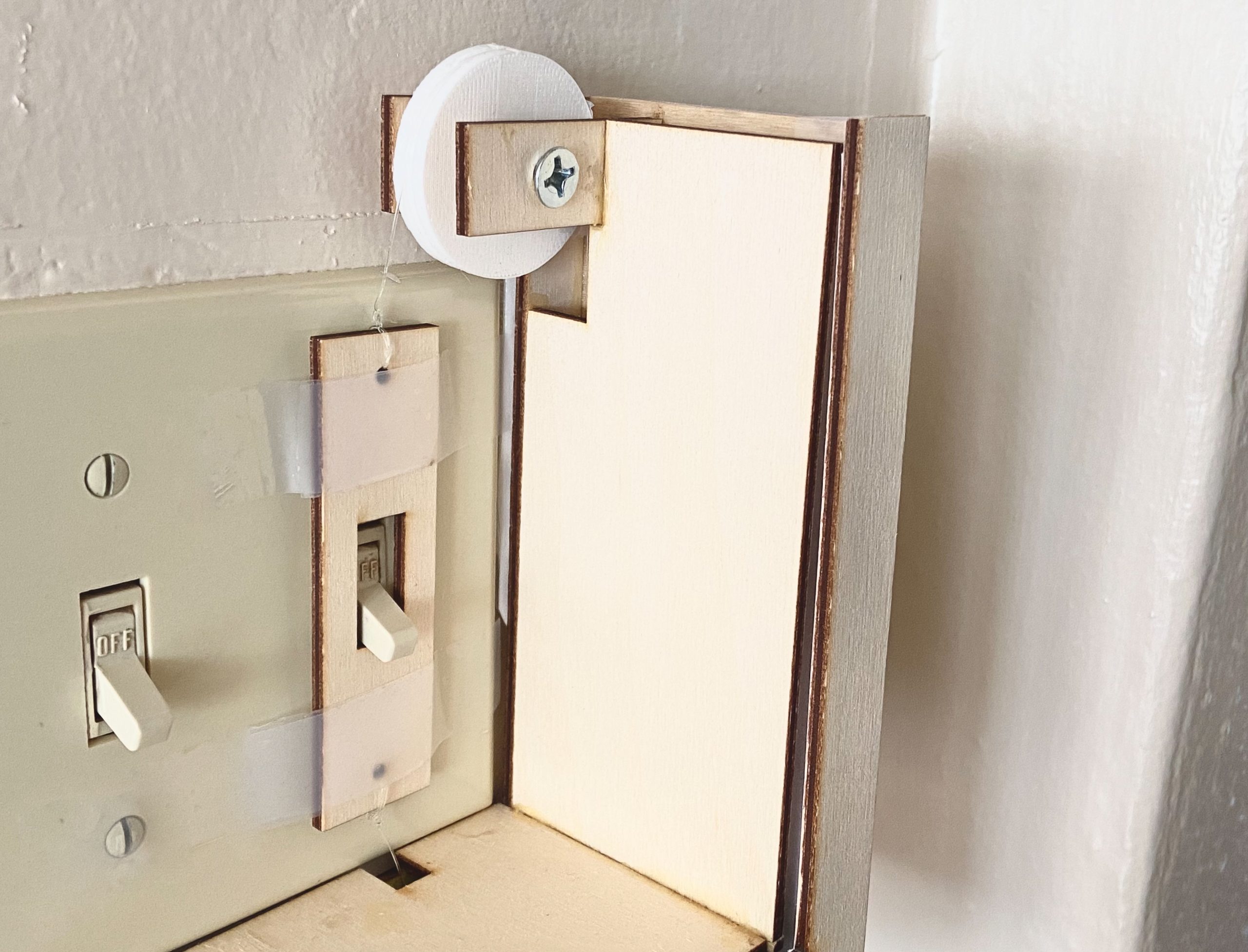
This is a close up of how the moving plate interacts with the rest of the device. There is a stepper motor underneath, which turns the pulley, pulling the plate up and down. There is tape that keeps the plate against the wall as it moves.
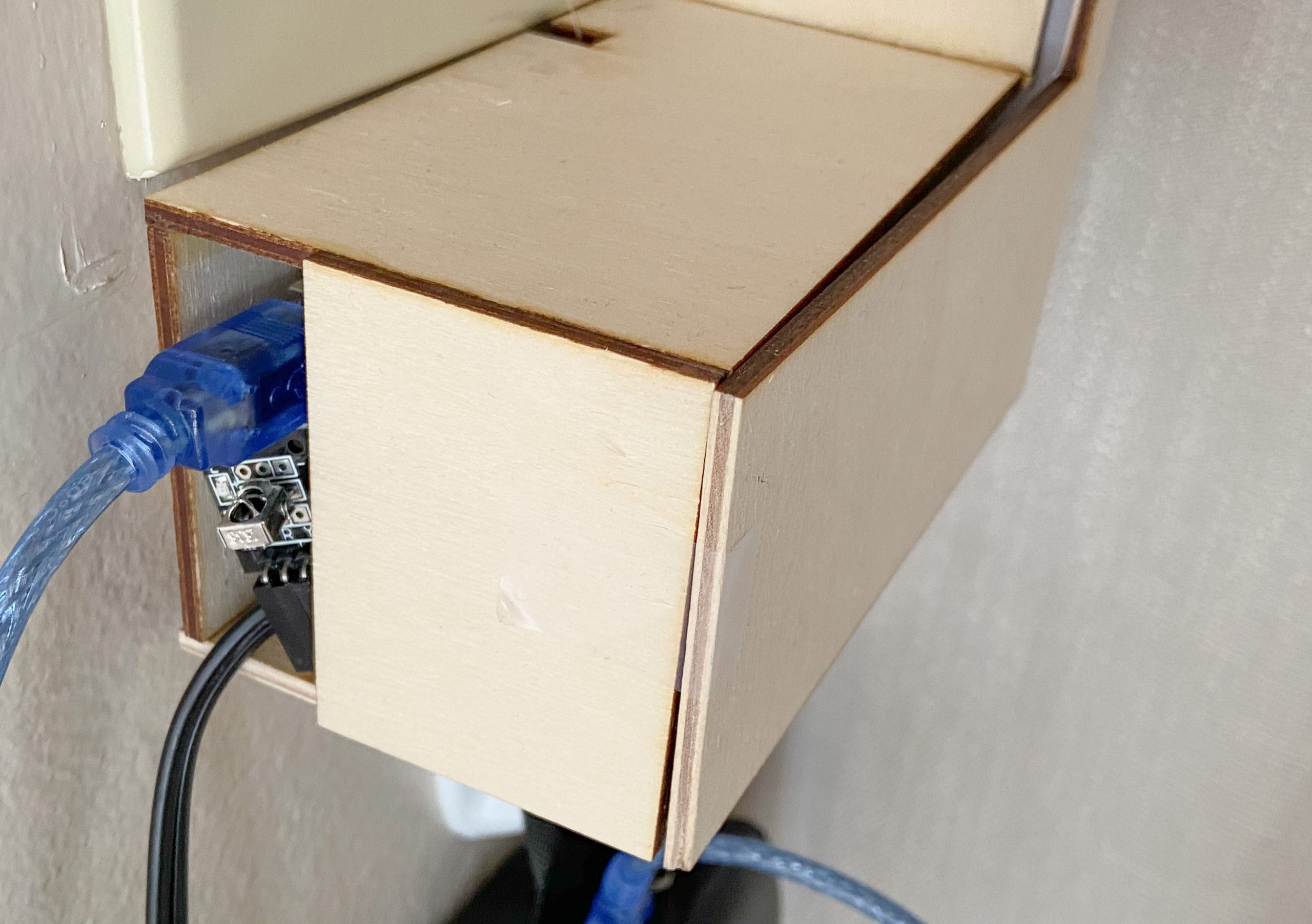
This is a close up of window for the infrared sensor as well as where the cables come out.
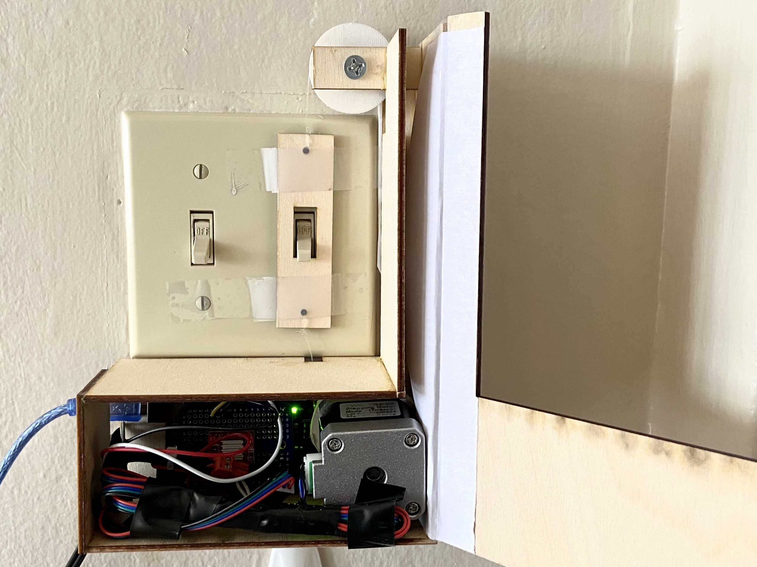
These are the insides of the device. From left to right, there is an infrared sensor, Arduino, protoboard(with the stepper motor driver), and stepper motor, which has the string tied to it.
Device in Use:
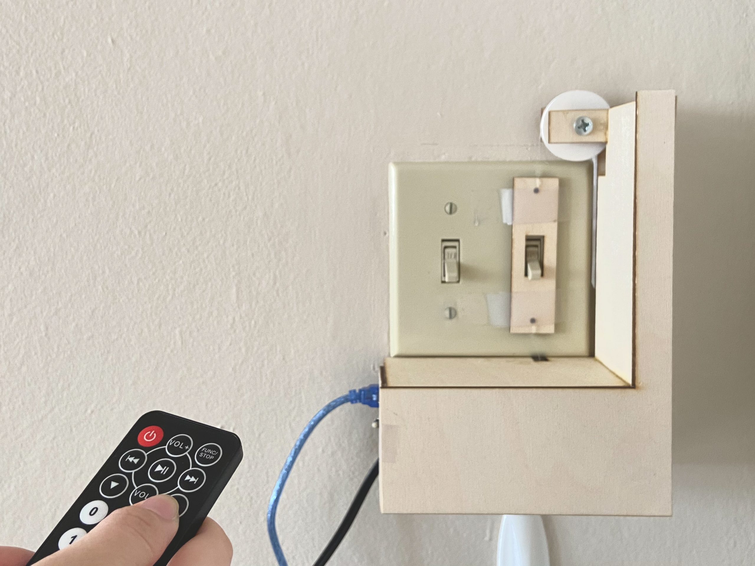
Remote control pointed at device, the finger is over the “up” arrow button, ready to turn the light switch on.
Process Images & Review:
Wooden Casing:
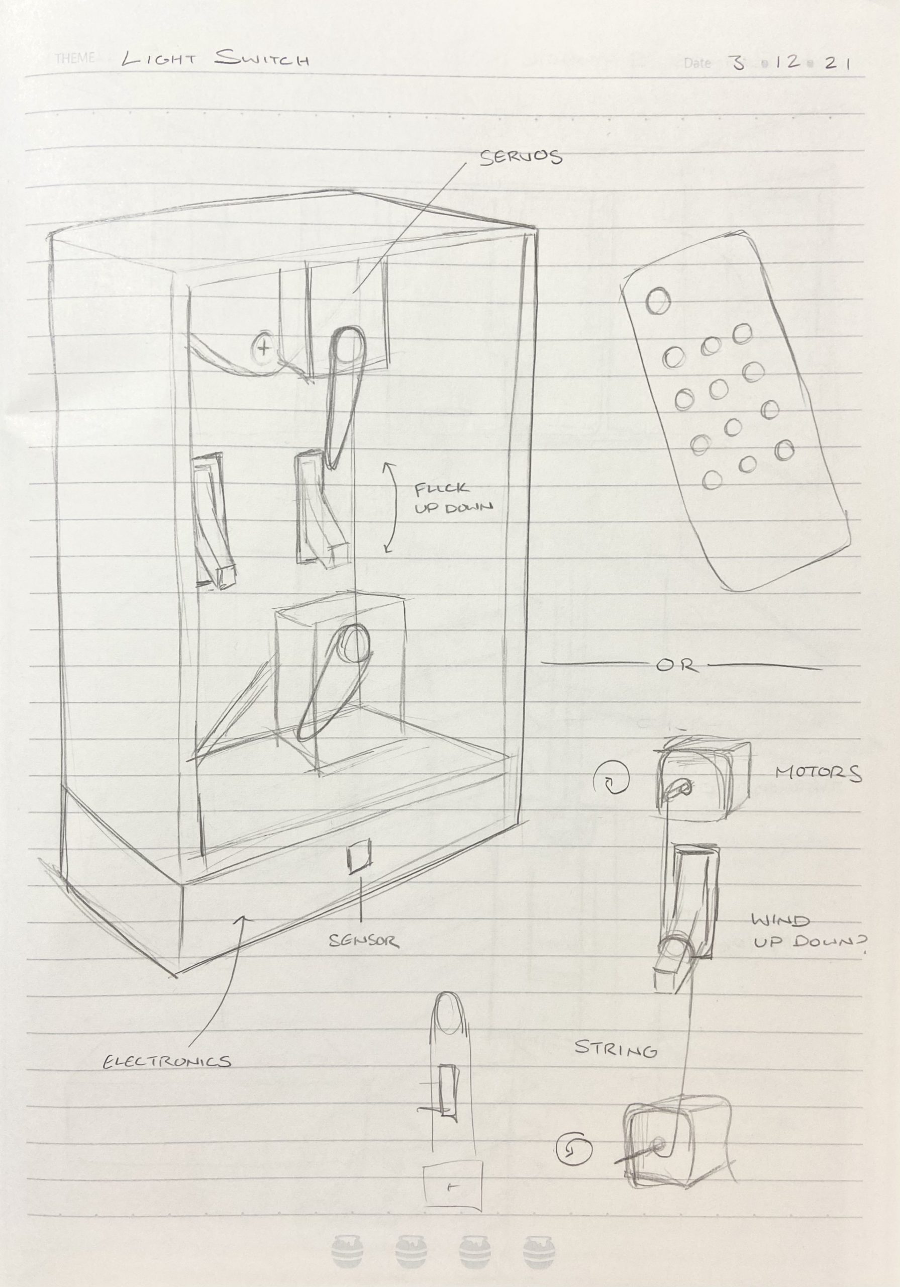
This was the initial sketch idea, the first consisting of two servos, and the second of two motors, both controlled by a remote control. After a meeting with the professor, we determined that one stepper motor with a pulley would do the job just as well. This greatly influenced my next design, as seen in the next image.
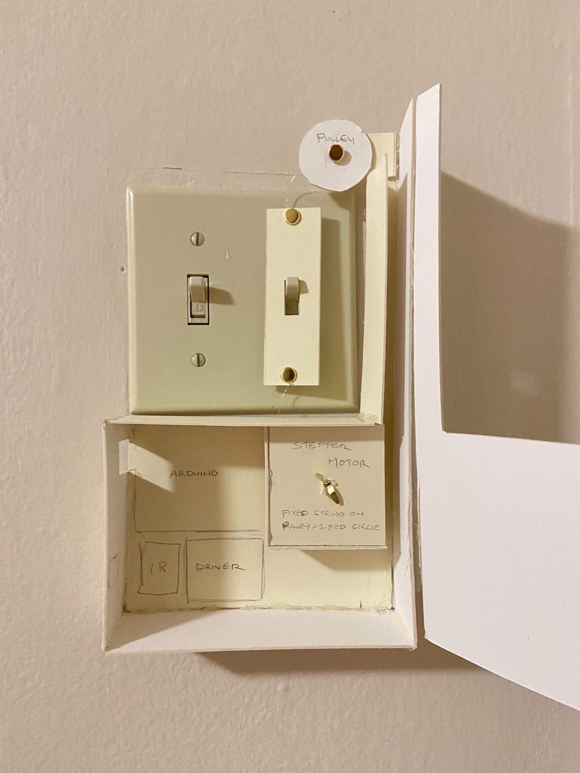
Looks-like prototype I made after solidifying the mechanism I wanted to create (stepper with pulley). Here, I figured out the arrangement I wanted. The idea was that a part of the string would be fixed to the stepper motor, and that would turn the pulley, moving the switching piece up and down. At this point in time I didn’t receive the stepper motor and stepper driver yet, so these were rough estimates.
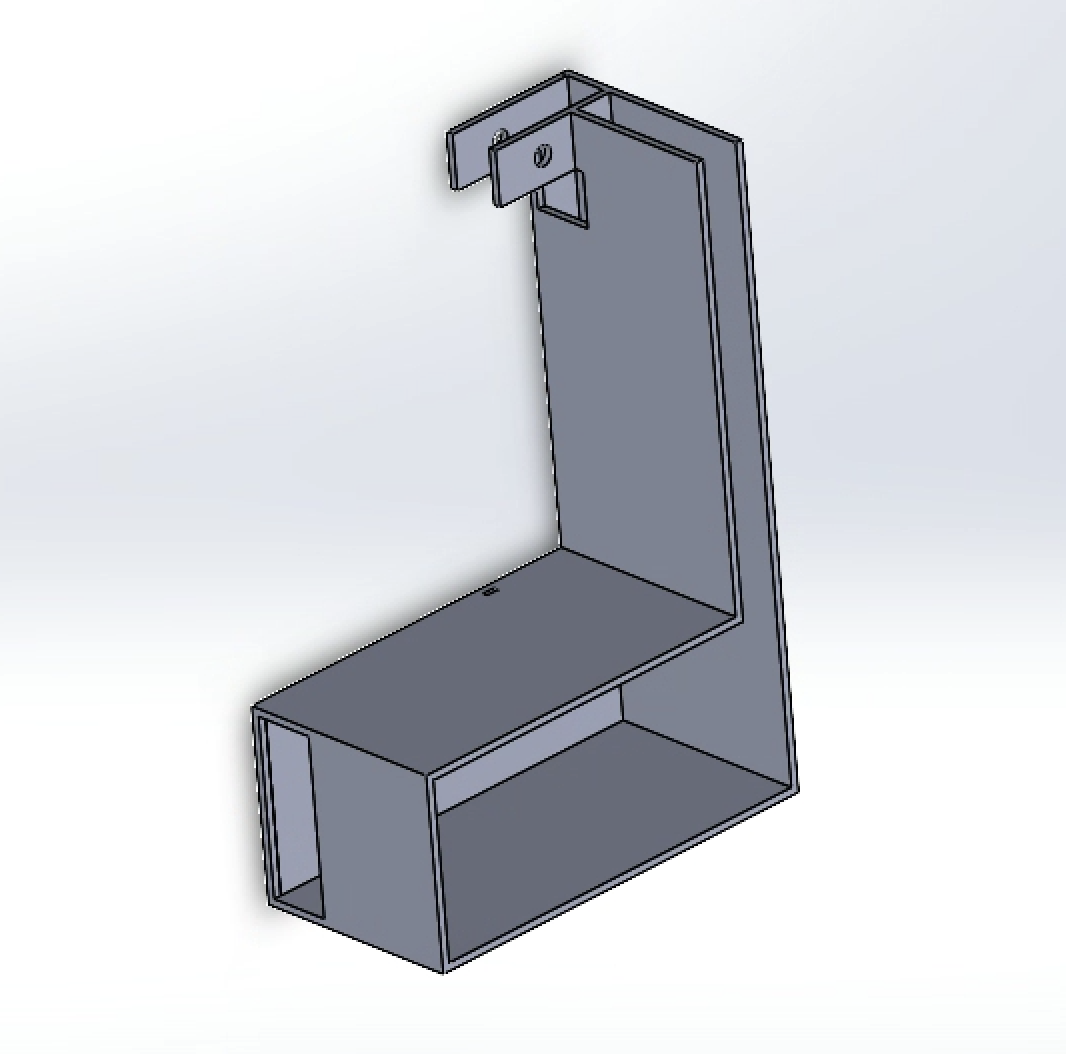
When I received the stepper motor, it was a lot taller than I expected, as a result I had to make the casing a lot thicker, but as a result, there was enough space to stack the Arduino and protoboard, saving space. Due to the stepper motor’s need for external power, I made the window at the side much larger, serving as a window for cables and the infrared sensor.
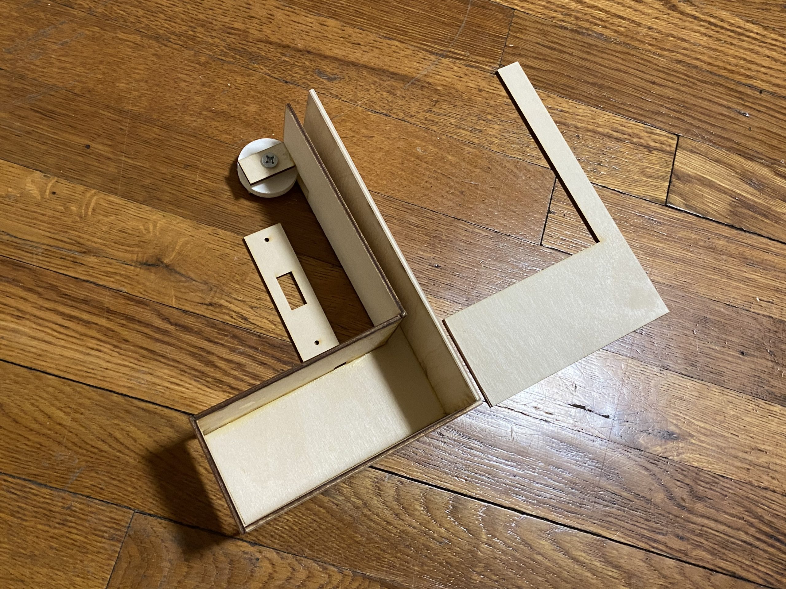
The final model laser cut pieces assembled together.
This was the first time I used a laser cutter and 3D printer, so each step was very new and unknown, but overall, it was a great experience.
Pulley Pivot:
Picture showing string refusing to stay on the disc (original plan was to superglue the string to the disc)
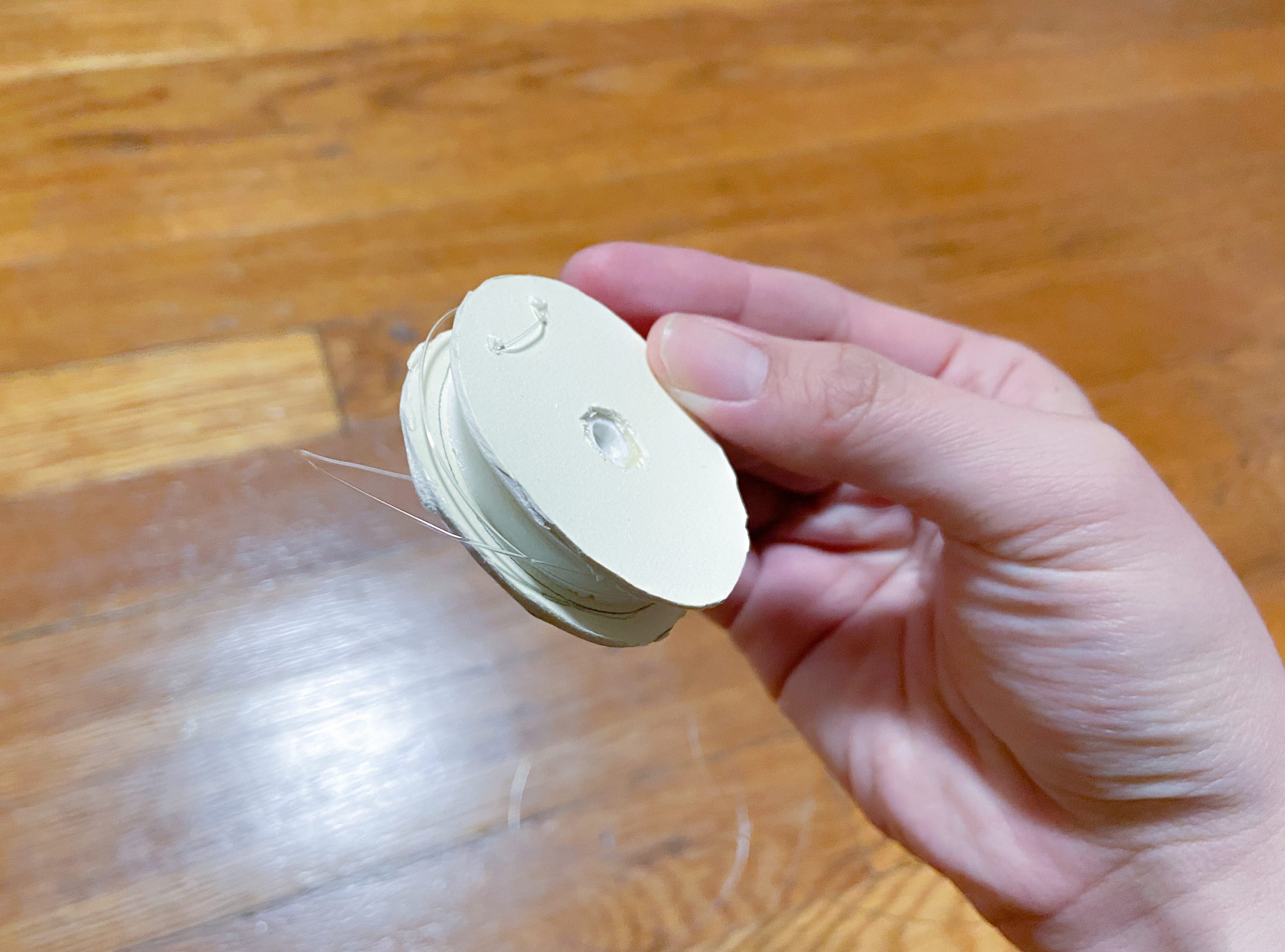
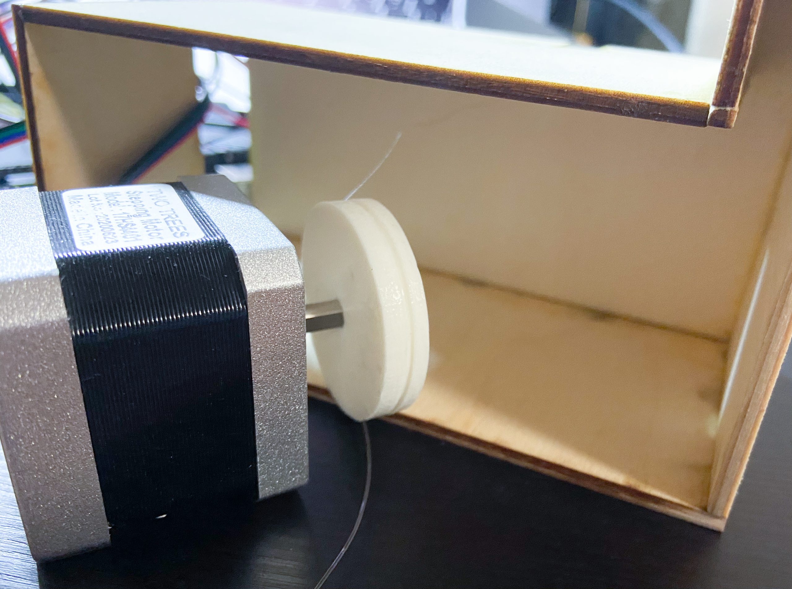
Final Solution: I cut two larger circles out of matboard and superglued it to the original 3D printed disc. Then, I poked two holes and tied the string to the new disc I made. This accomplished two things: the string was stable, and the string won’t fall out of the newly made grooves.
The main issue with the pulley was that the string would constantly come loose due to the strong force of the stepper motor. This caused me a lot of trouble, but eventually I believe I came with a that works well. Next time, I’d 3D print a disc with larger grooves and pre-made holes to tie the string to.
Discussion:
The comments gathered from my critique were an interesting mix, since some points others critiqued, others liked. Regarding the critiques about the device, one mentioned, “Work on mechanical noise, especially if it’s being used late at night.” Another stated that they liked the thunk sound, but I have to agree with the first person. Since it is to be used late at night, the sound, though quick, is a little loud. If I made another one, I could definitely try to find a way to dampen the noise through slowing the motor down or placing foam in places where pieces touch. Another critique I agreed with was, “The chair looks like it’s in the way a bit, maybe make a shelf for the power bank or tape it to the wall (in a nice way) so that you can move more easily in and out of the room.“ My original design didn’t use the massive power bank but instead the battery that came with the kit, which fit in the wooden casing. However, whenever I used it, I found that the stepper motor would jitter a lot. As a result, I changed to a power bank. I temporarily used a chair to keep the power bank from falling to the floor, and later used a headphone case to hang the power bank on the wall. In the future, I would make a wooden casing or shelf that could integrate the power bank well. What I found most difficult was making the pulley mechanism. I haven’t had much experience making mechanism, so my theory of how the device works didn’t always line up with how it actually behaved. If there was more time for this project, I think I would’ve started by experimenting with how the mechanism would work first. That would smooth out the workflow a lot.
Overall, I’m pretty happy with the outcome, all things considered. A comment basically sums up my goal, “I really like the thought that went into designing the actuation and how it interfaces with the light switch.” I wanted to create a device that would look like it’s a part of the light switch, and also work. Ideally, the device would be thinner or be pushed into the wall, but with current constraints, (large stepper motor, renting), that wouldn’t be possible. I think the craft could have been improved, but given that this was my first time using a laser cutter and 3D printer I think it’s not horrible, and now that I have this experience, I know what works and doesn’t, and my device designs can only improve from now. If I could give advice to my past self, I’d say that when using new machines, it’s best to start working on them early, so if something fails, there’s time to use the machine again.
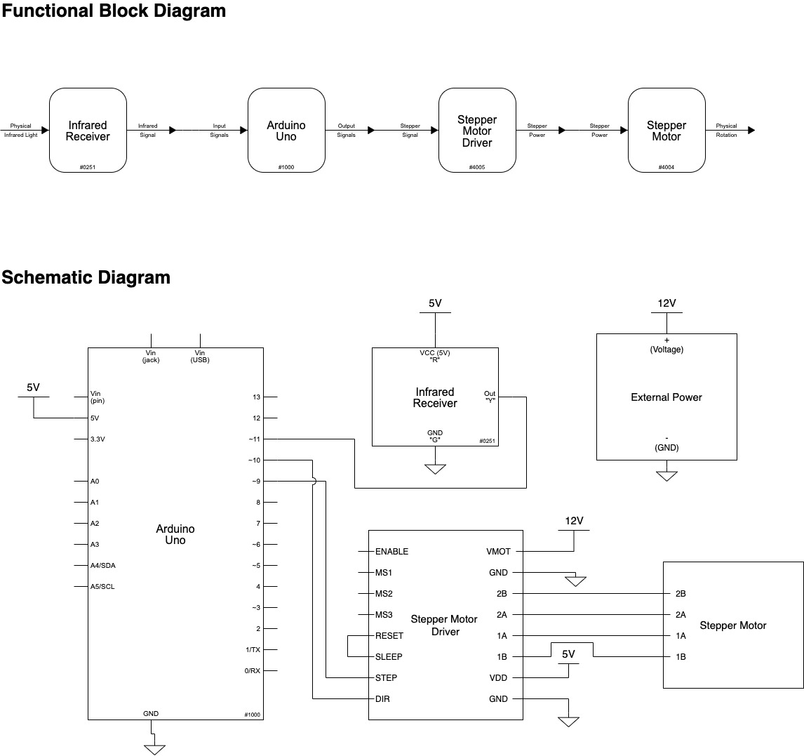
Technical Information:
Functional Block and Schematic Diagrams:
Code:
/*
   Personal Assistive Device: Light Switcher
   By: Nicole Yu

   Description:
    A device that flips the light switch on and off
    from a distance

   Pin Mapping:

    Arduino pin | type   | description
    ------------|--------|-------------
    9             output   Stepper Motor [Step Pin]
    10            output   Stepper Motor [Direction Pin]
    11            input    IR Sensor

   Credit:
    1. How to wire and code the stepper motor:
    www.youtube.com/watch?v=GgfgWU0bpHk
    2. How to code the IR Sensor:
    www.youtube.com/watch?v=9cJT-tfODsg

*/


#include <IRremote.h>

const int STEPPIN = 9;   //pin to pulse for steps
const int DIRPIN = 10;   //pin to change step direction
const int RECVPIN = 11;  //IR sensor

void setup() {

  Serial.begin(9600);

  // IR SENSOR PINS
  IrReceiver.begin(RECVPIN, ENABLE_LED_FEEDBACK);

  // STEPPER MOTOR PINS
  pinMode(STEPPIN, OUTPUT);
  pinMode(DIRPIN, OUTPUT);
}


void loop() {

  if (IrReceiver.decode()) {
    Serial.println(IrReceiver.decodedIRData.decodedRawData, HEX);
    switch (IrReceiver.decodedIRData.decodedRawData) {

      // TURN OFF LIGHT
      case 0xF609FF00: // remote: down button

        stepperREV(); // flip switch down
        for (int i = 0; i < 50; i++) {
          motorStep();
          delay(1);
        }
        stepperFWD(); // back to center
        for (int i = 0; i < 50; i++) {
          motorStep();
          delay(1);
        }
        break;

      // TURN ON LIGHT
      case 0xF807FF00: // remote: up button

        stepperFWD(); // flip switch up
        for (int i = 0; i < 50; i++) {
          motorStep();
          delay(1);
        }
        stepperREV(); // back to center
        for (int i = 0; i < 50; i++) {
          motorStep();
          delay(1);
        }
        break;
    }
    IrReceiver.resume();
  }
  delay(10);
}
// DIRECTION OF STEPPER

//change the stepper direction to forward
void stepperFWD() {
  digitalWrite(DIRPIN, HIGH);
}

//change the stepper direction to reverse
void stepperREV() {
  digitalWrite(DIRPIN, LOW);

}
// STEPS STEPPER TAKES

//have the stepper motor take one step
void motorStep() {
  digitalWrite(STEPPIN, HIGH);
  delay(1);
  digitalWrite(STEPPIN, LOW);
}