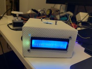
Message Box
The Message Box is meant to be a more unique, personal, and interactive way to send digital messages to my girlfriend by using a stepper motor to notify her of new messages and introducing the physical constraints that it needs to be plugged in.
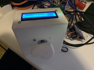
Top view
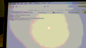
Web interface
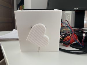
Front view of rotating heart
Process Images and Review
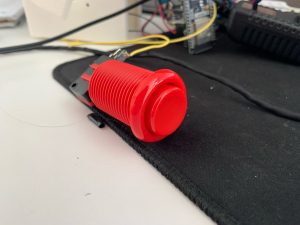
One decision point on my project was to use a button to indicate that the user had read a message rather than sensing a lid using a hall sensor. I chose to do this as my hall sensor broke when I was soldering my components to the protoboard and unfortunately could not get a replacement in the two days before the project was due. I was not happy I had to make this decision, but it was important to the functionality of my device.
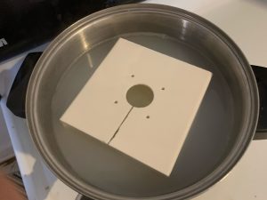
DIY parts washer
Another decision point was to 3D print my enclosure rather than laser cutting it or making it in the woodshop. This was a pain point for my project as I designed and submitted it several days in advance, but ended up facing issues with parts not fitting as well as having to make a DIY parts washer at home.
Test fit of 3D printed parts
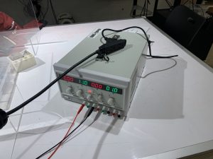
My original power supply
Another struggle for my project and decision point was selecting a power supply. I found out that the 5v brick we got in our kits was nowhere near enough to power the large stepper motor I was planning on using. We initially had to use this giant power adjustable power supply to make the motor move properly, but I ended up finding an old power supply and taking it for parts to power my stepper motor.
Discussion
Response to Criticism
“I think the button is a little bulky and seems aesthetically very different from your white box. Maybe in a different model you could incorporate the button into the box.”
This criticism along with the fact that my electronics didn’t fit into the case is fair and I agree with it. Unfortunately my soldered components barely wouldn’t fit into my 3D printed case without possibly damaging the components and it was too late to print another before the demo. The button was an unfortunate addition I had to make last minute as my hall sensor broke when I was trying to solder wires to connect it to my project. I was going to make a magnetic lid that could be used to clear the LCD as well as turn the backlight on/off/
“The 3D printed components really add to the overall aesthetic and it looks really cool! I also like the idea of making messages more special because there are so many different apps now but this is super cute.”
I am very glad that my project seems like a more unique way to convey a message! This was the overall goal of my project and although I will need to reprint my case, the electronics and concept working together makes it successful.
Self-Critique
I learned that I have a lot to learn about designing physical components for a novel project is very challenging. I designed the enclosure for my project so that everything would fit with what I thought was a decent amount of extra space as wiggle room. This ended up being an issue from the moment I got the enclosure, as the stepper motor just barely would not fit without a modification to the case due some remaining support material from the 3D print. I cut a slot in the case to allow the stepper motor shaft to fit into the case in case it wouldn’t fit once the support material dissolved. It ended up being an unnecessary modification once I finished washing the part at home, but it would have been much better to have that slot than not be able to mount the motor if it didn’t fit. Another enclosure issue I had was that it just barely did not fit my electronic components inside of the case. Less than one more inch of width or depth would have been allowed everything to fit. I learned that I have to be a bit more liberal when designing enclosures and if there is a lot of extra space to size down on a future iteration.
Despite the enclosure issues, I still had some major successes and positive learning throughout this project. The final product exceeded my expectations in terms of interactivity and the user experience. Sending a message is as seamless as going to a website and clicking a button. The notification from the stepper motor ended up being a perfect way to catch someone’s attention. I fell in love with the idea of having a movement as the notification method when coming up with ideas for this project, but felt like I would need some sort of noise or light to really draw someone to the box when there was a new message. This ended up being totally unnecessary since the stepper motor makes sounds as it spins! Sounds from the stepper motor are in sync with the movement, creating a very fluid audio-visual effect that was much better than what I initially envisioned for this project.
This project was also my most technically complex project and felt like much more of a “finished” project electronically than anything I had before. I worked with a lot of new components, such as capacitors, voltage regulators, and the stepper motor driver as well as had to solder more connections than I have used before. The fact that I was able to just plug it into a wall outlet and have it start working immediately made the project feel like I had actually made something that could be used in real life rather than some small project that we would need to take apart in a few days. With all that said, I think I would spend more time planning my protoboard connections than I did on this project. Although I did try to plan it out beforehand, I had to make extra power/ground rails twice over and did not place the components in a very efficient manner which resulted in a rat’s nest of wires.
Next-Steps
My most immediate next step is to redesign my case so that it can fit all of my electronics mounted inside of the case. I still hope to be able to give this to my girlfriend before I graduate and move this summer. From there I hope to be able to design a slightly more complex webpage that allows clients to send custom messages or even images if I am willing to upgrade from our 16×2 LCD and redesign the enclosure.
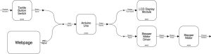
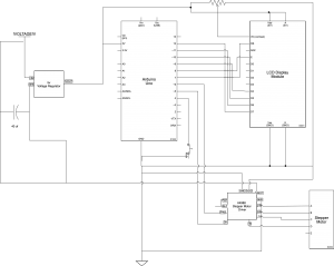
Technical Information
Please note for the block diagram and schematic I used the Arduino Uno rather than the esp32 I used in my project. Substitute the pins in the schematic for the pinout from the sketch if you are trying to replicate my project.
/*
60-223, Project 2: Message Box
Kevin Bender (kbender1)
time spent: ~14 hours
Description: This code hosts a simple webpage and allows a user to send a message to the message box.
When a remote client sends a new message, the message is displayed on the LCD screen and
the stepper motor spins until someone presses the button to acknowledge receipt of the message
Collaboration and sources:
1) I drew inspritation for my project from a product called the "lovebox"
(https://en.lovebox.love)
2) https://github.com/espressif/arduino-esp32/blob/master/libraries/WiFi/examples/SimpleWiFiServer/SimpleWiFiServer.ino
I borrowed code from this example project which hosts a simple wifi server which can blink an LED depending on
input to the webpage
3) I learned wiring for the stepper motor driver and how to code it from https://lastminuteengineers.com/a4988-stepper-motor-driver-arduino-tutorial/
as well as the course website
4) I borrowed code and the wiring from the elegoo manual for the LCD screen included with our kits
Pin mapping:
Arduino pin | type | description
------------|--------|-------------
26 output Stepper motor step pin
27 output Stepper motor direction pin
32 input pushbutton to acknowledge messages
2 output LCD pin A
4 output LCD pin B
5 output LCD pin C
18 output LCD pin D
19 output LCD pin E
21 output LCD pin F
*/
#include <LiquidCrystal.h>
#include <WiFi.h>
#include <AccelStepper.h>
const int STEP_PIN = 27; // A4988 "STEP" pin wired to Arduino pin 2 (you can change this)
const int DIR_PIN = 26; // A4988 "DIRECTION" pin wired to Arduino pin 3 (you can change this)
const int BUTTON_PIN = 32;
// make an AccelStepper motor object. "myMotor" can be any name you'd like.
AccelStepper myMotor(1, STEP_PIN, DIR_PIN);
int pos = 600; // variable to store motor position instruction
const char* ssid = "Ypur SSID";
const char* password = "password";
boolean shouldRotate = false;
WiFiServer server(80);
// initialize the library with the numbers of the interface pins
LiquidCrystal lcd(2, 4, 5, 18, 19, 21);
void setup() {
pinMode(BUTTON_PIN, INPUT_PULLUP);
// set up the LCD's number of columns and rows:
lcd.begin(16, 2);
// you can change the below values as you'd like
myMotor.setMaxSpeed(1000); // measured in steps per second
myMotor.setAcceleration(400); // measured in steps per second squared
// Print a message to the LCD.
delay(10);
// We start by connecting to a WiFi network
lcd.println("connecting");
WiFi.begin(ssid, password);
while (WiFi.status() != WL_CONNECTED) {
delay(500);
// Serial.print(".");
lcd.println("still connecting");
}
lcd.clear();
pinMode(23, OUTPUT);
lcd.println(WiFi.localIP());
server.begin();
}
int value = 0;
bool switch1 = false;
bool isH = false;
void updateMotor() {
if (shouldRotate) {
if (myMotor.distanceToGo() == 0) { // if the motor arrived
pos = -pos; // then change its destination
myMotor.moveTo(pos); // and tell the motor to go there
}
myMotor.run();
}
if (digitalRead(BUTTON_PIN)) {
shouldRotate = false;
lcd.clear();
}
}
void loop() {
WiFiClient client = server.available(); // listen for incoming clients
updateMotor();
if (client) {
lcd.clear();
lcd.println("client connecting");
// if you get a client,
String currentLine = ""; // make a String to hold incoming data from the client
while (client.connected()) { // loop while the client's connected
updateMotor();
if (client.available()) { // if there's bytes to read from the client,
char c = client.read(); // read a byte, then
if (c == '\n') { // if the byte is a newline character
// if the current line is blank, you got two newline characters in a row.
// that's the end of the client HTTP request, so send a response:
if (currentLine.length() == 0) {
// HTTP headers always start with a response code (e.g. HTTP/1.1 200 OK)
// and a content-type so the client knows what's coming, then a blank line:
client.println("HTTP/1.1 200 OK");
client.println("Content-type:text/html");
client.println();
// the content of the HTTP response follows the header:
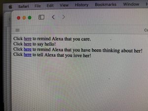
client.print("Click <a href=\"/H\">here</a> to remind Alexa that you care.<br>");
client.print("Click <a href=\"/L\">here</a> to say hello!<br>");
client.print("Click <a href=\"/G\">here</a> to remind Alexa that you have been thinking about her!<br>");
client.print("Click <a href=\"/J\">here</a> to tell Alexa that you love her!<br>");
// The HTTP response ends with another blank line:
client.println();
// break out of the while loop:
break;
} else { // if you got a newline, then clear currentLine:
currentLine = "";
}
} else if (c != '\r') { // if you got anything else but a carriage return character,
currentLine += c; // add it to the end of the currentLine
}
// Check to see if the client request was "GET /H" or "GET /L":
if (currentLine.endsWith("GET /J")) {
if (isH) {
switch1 = false;
} else {
switch1 = true;
}
isH = true;
digitalWrite(23, switch1);
lcd.clear();
lcd.println("Kevin loves you!");
shouldRotate = true;
}
if (currentLine.endsWith("GET /G")) {
if (isH) {
switch1 = true;
} else {
switch1 = false;
}
isH = false;
digitalWrite(23, switch1);
lcd.clear();
lcd.println("Kevin has been t");// GET /L turns the LED off
lcd.setCursor(0, 1);
lcd.println("hinking about you!");
shouldRotate = true;
}
// Check to see if the client request was "GET /H" or "GET /L":
if (currentLine.endsWith("GET /H")) {
if (isH) {
switch1 = false;
} else {
switch1 = true;
}
isH = true;
digitalWrite(23, switch1);
lcd.clear();
lcd.println("Kevin cares!");
shouldRotate = true;
}
if (currentLine.endsWith("GET /L")) {
if (isH) {
switch1 = true;
} else {
switch1 = false;
}
isH = false;
digitalWrite(23, switch1);
lcd.clear();
lcd.println("Kevin says hello!");// GET /L turns the LED off
shouldRotate = true;
}
}
}
// close the connection:
client.stop();
}
}