Overview:
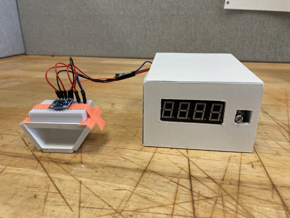
Pomodoro Timer: a studying technique that alternates between periods of work and rest. Periods of work usually last from 30 min – 1 hour, while periods of rest last from 2 min – 5 min. This timer stores these times as separate values which can be adjusted while the tilting mechanism is in its neutral state, with tilting to one side starting the work timer and the other starting the rest timer. The end of time is announced by a buzzer.
Detail Photos:
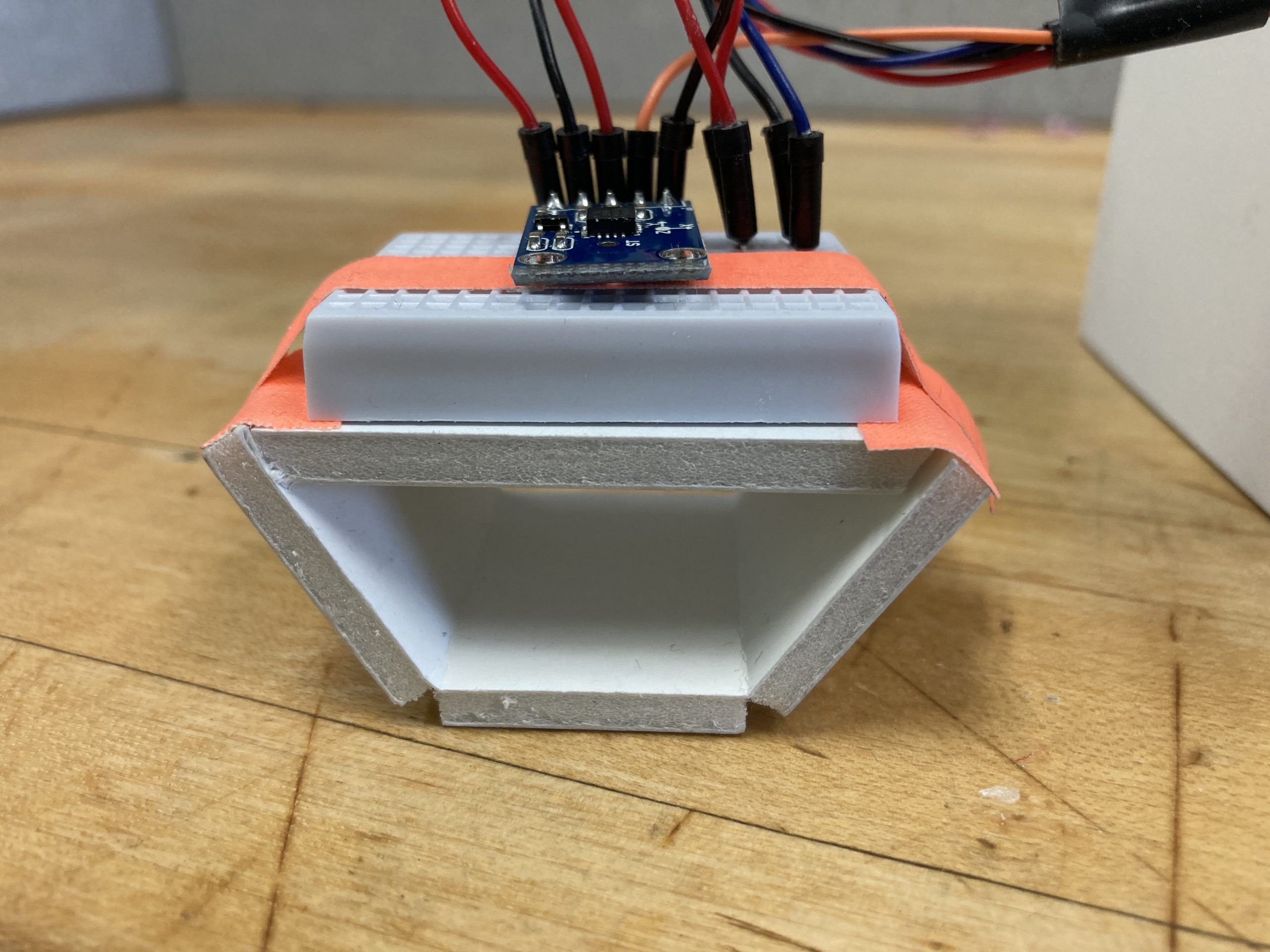
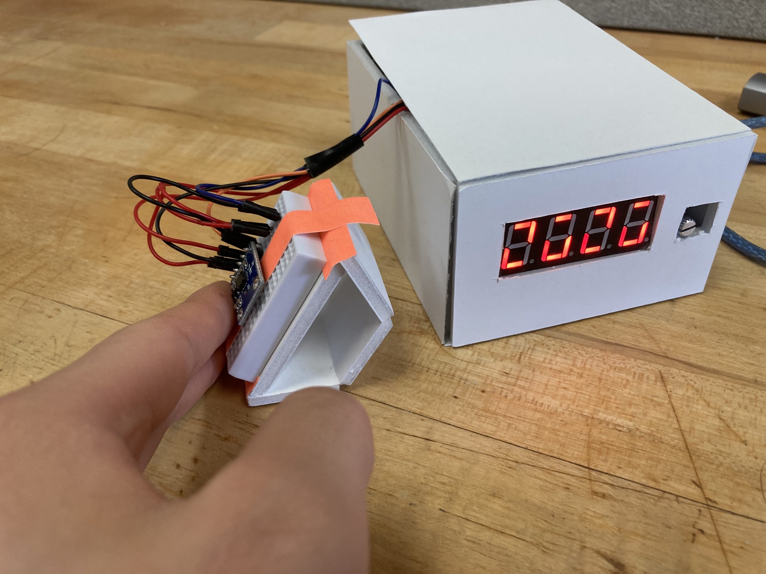
Timer tilt sensor. Tilting to one side will trigger the work timer to start, the other the rest timer. Keeping it in the middle lets users adjust the times stored for both.
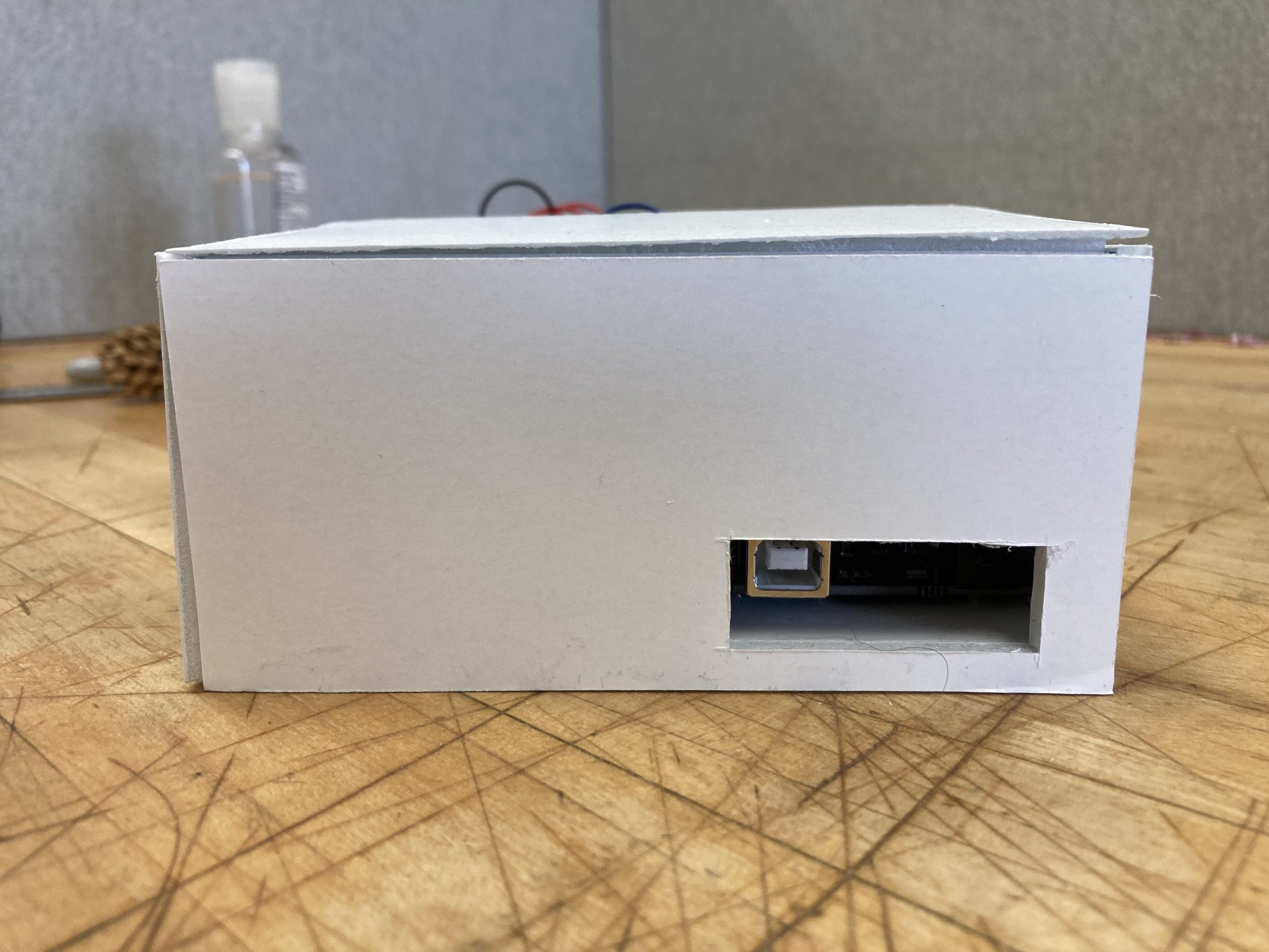
Main housing side view. The hole cut in the side of the box is for power cables or connections to the computer.
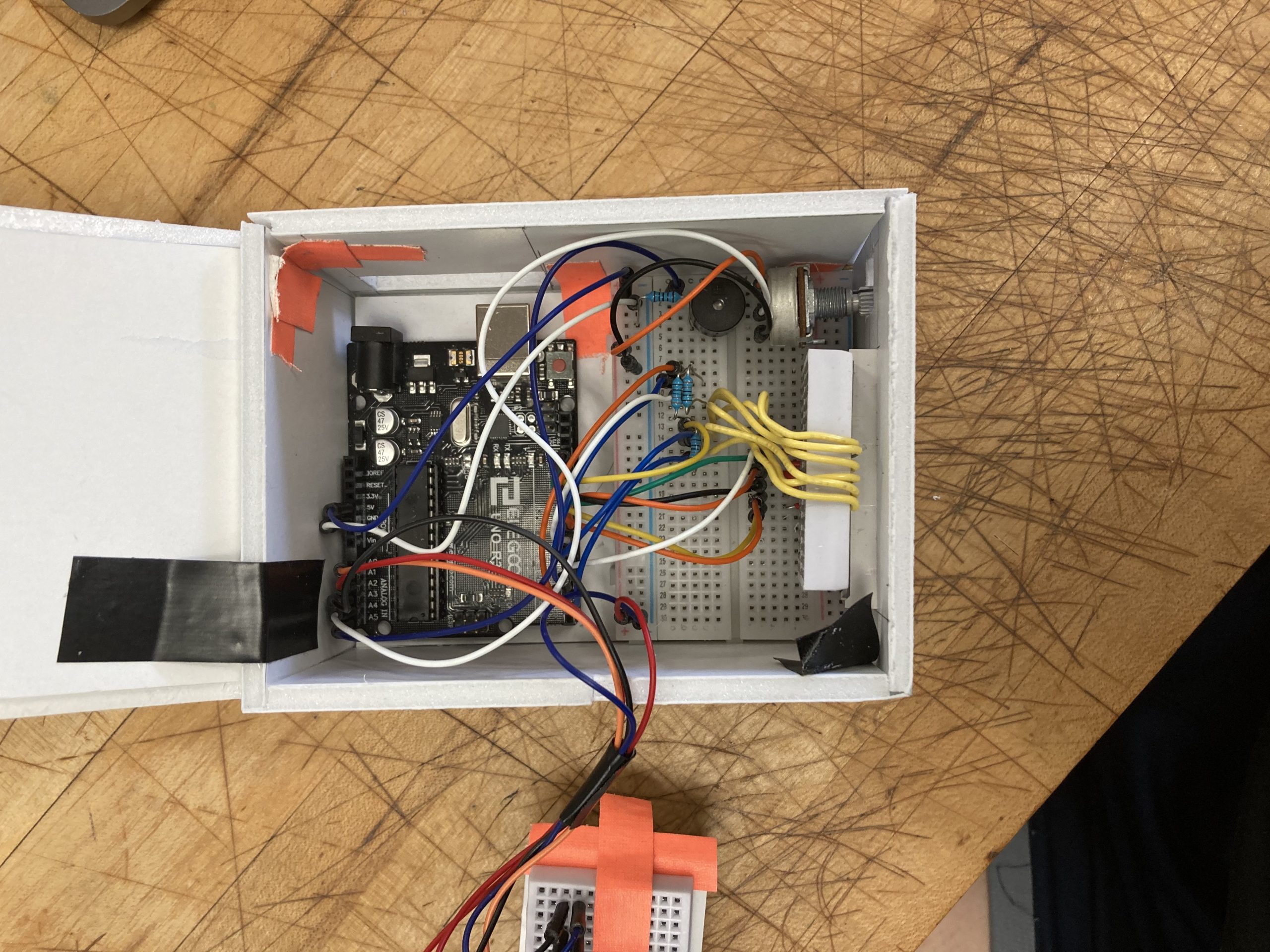
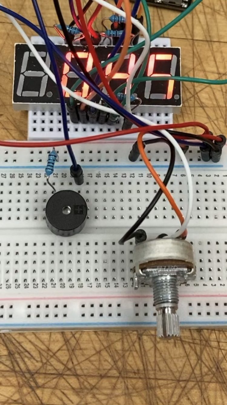
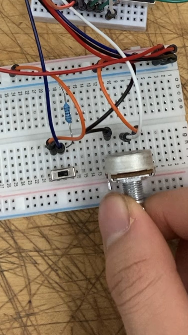
The wiring and connections inside the timer.
Timer in Use:
User adjusting the time stored with the knob on the side.
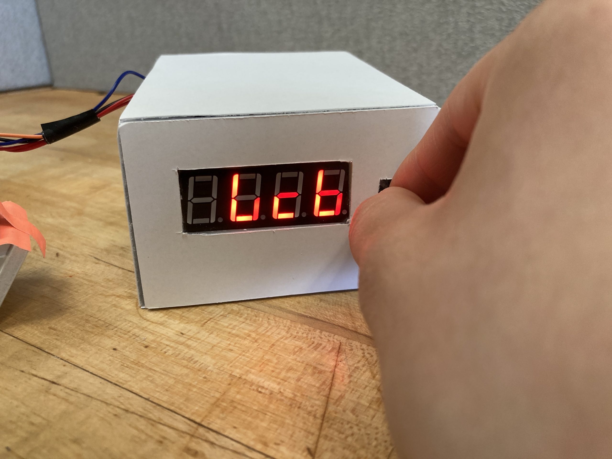
A user operating the tilt sensor to start the timer.
*Note, the numbers appear distorted in these still images because the display draws the numbers step by step but appear normally when viewed in real time.
Video Demonstration:
*Note video speed increased to decrease file size.
Process Images and Review
Decision Point 1: Using the 4 digit, 7 segment display instead of the LCD display. I chose this display because of the display size, number of digits and larger font size compared to the LCD display. Unfortunately, however, this type of display didn’t have any documentation on the website and I had to cycle through several tutorials to find one that worked. Additionally, the code I ended up using doesn’t draw all parts of the digits at the same time, so they appear distorted in still images.
Still image of the display. The numbers appear distorted
Decision Point 2: Because the display I used took up so many digital pins, I only had a few pins left to signal to the user that the timer had expired. At first I was thinking about using a series of LEDs to indicate the state the timer is in. However, I decided that LED indicators would not be visible enough to the user to signal time expiring and decided to use a buzzer instead.
Wiring and internal workings.
Process Images:
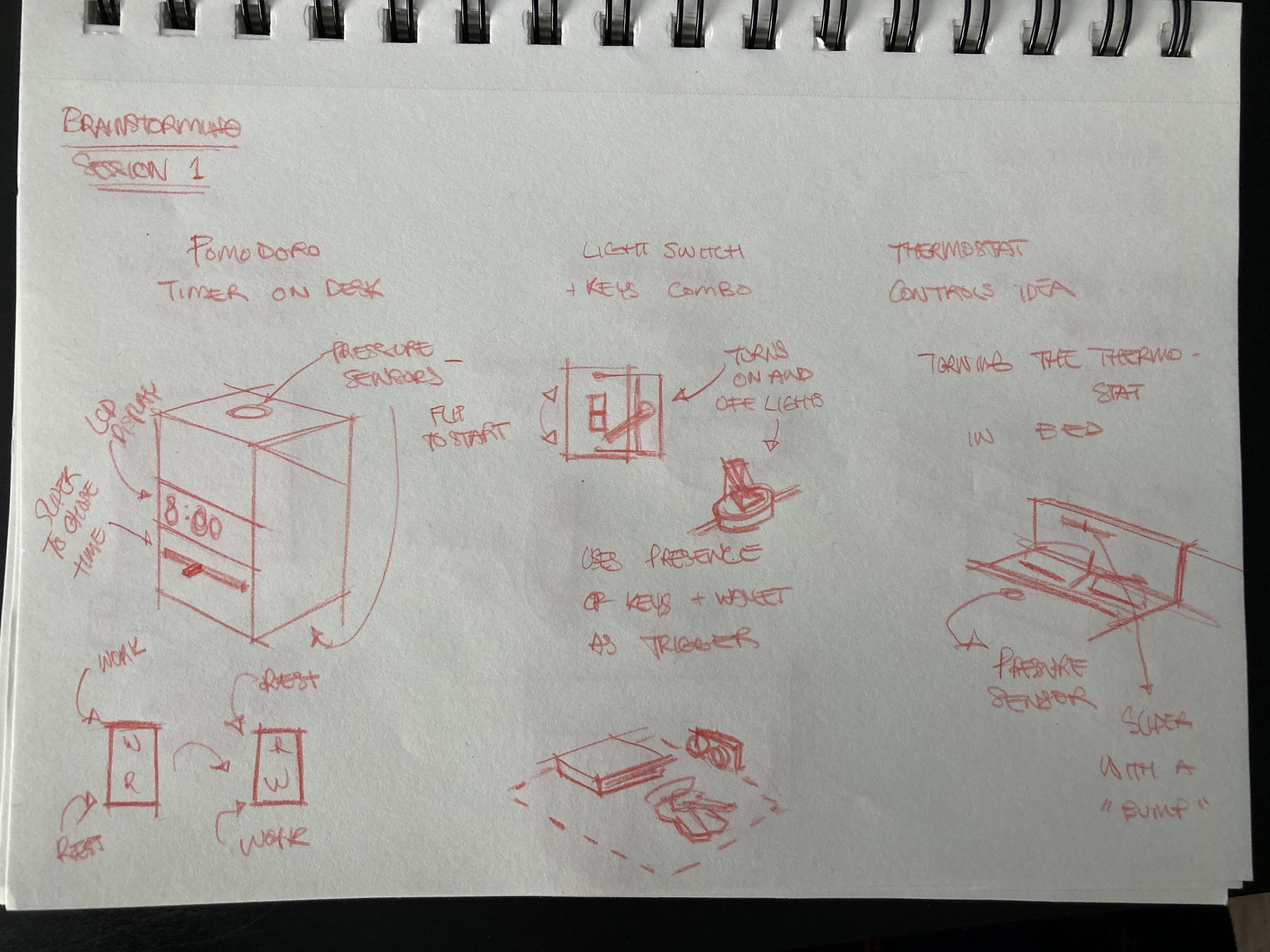
Original Sketches
Added Buzzer In the place of LEDs
At this point, I was considering an extra switch for toggling power
Discussion
Response to comments gathered during the in-class crit. Quote (verbatim) from at least two written critiques that you received (positive, negative, or otherwise) from the in-class crit, and respond to them. (You may agree or disagree—in either case, explain your position.)
- Wonder if you could condense this into one single unit instead of making the accelerometer module separate from the LCD and buzzer screen?
- Maybe would’ve been cool to have the tilt mechanism physically separate from the main housing so it can be taken farther away
Addressing the first point, I wanted to keep the accelerometer module separate from the display and buzzer because combining them in one unit would mean that tilting the unit also tilts the display as well which might be awkward to view. At the same time, I wanted to keep the component the user actually tilts quite shorter and more independent because I wanted it to be smaller. To me, the difference between the interaction of a smaller and larger module were too high. A larger module would be something that you would use your hand or palm to tilt, whereas a smaller module would be something that you would use your finger tilted.
I was also thinking about the relationship between the accelerometer and main housing in terms of physical distance, and while I would have liked to keep them physically separate, I didn’t have the means to at the time because of the physical connection of the wires. At the same time, I didn’t want them to have no relationship because it would feel disconcerting if the trigger was physically separated from the display too far. Ideally, I would have nestled the tilting piece against the housing in some way.
- Maybe work on physical interface for the potentiometer? Seems difficult to rotate
- ^there’s knobs for the potentiometer in the lab
- Maybe have the tilt indicate if you are on rest or focus mode, could change something either on the display or just physically
- Maybe make the object you tilt look like a tomato 🙂
Something that I ended up having to make concessions on was the physical form of the timer. I made the housing from foam core and created simple boxes and left the potentiometer without additional adjustment. However, I would have ideally wanted to make the form itself more elegant and ergonomic in a way that made the timer itself easier to use.
Self critique pertaining to the project. Are you happy with how the project came out? Did it satisfy your own goals? This should not simply be a recital of your process, but rather a meaningful reflection.
While I am happy that the code and functionality of the project itself worked out perfectly with little to no bugs, I am a little disappointed in how far I was able to take the form of the timer itself. Although the end product looked relatively clean, I would have liked to make it more elegant and ergonomic as I had said above.
What you learned about your own abilities and/or limitations through the process of working on this project. These could be technical in nature (i.e. “I found that coding this particular behavior was surprisingly difficult”), or not (i.e. “I enjoyed making cardboard forms very much, and I think it will be a useful prototyping medium for me in the future”). What would you do differently next time? What would your advice to your past self be? Did you get hung up at a particular point in progress, or fail to see an easy workaround to a problem? Did you find a creative spark you didn’t anticipate? Etc.?
I had learned from previous projects not to be over ambitious about what I could achieve during the time limit and decided to focus more primarily on the coding and Arduino portion of the project and to keep the form simple. However, in the end I found that I wish I had pushed myself a bit more to perhaps 3D print some of the form or to have put more effort into that front.
Next steps. Do you expect to build another iteration of this project? If so, describe what you’re planning to do. If not, describe what you would do if you were to build another iteration, based on the experience you had with this first one.
I am planning to keep working on this project. I would like to miniaturize the wiring and create a more polished form around the object itself.
Technical Information
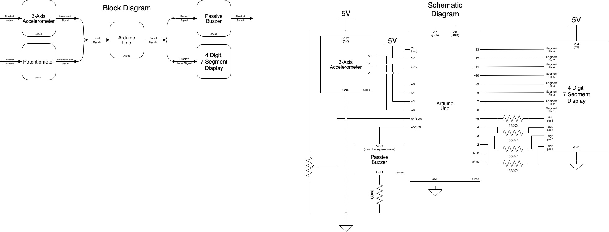
Schematic and Block Diagrams:
Code:
/*
 * 60-223, Project Two: Assistive Device
 * Daniel Zhu (dszhu)
 *
 * Pomodoro Timer: a studying technique that alternates between
 * periods of work and rest. Periods of work usually last from
 * 30 min - 1 hour, while periods of rest last from 2 min - 5 min.
 * This timer stores these times as separate values which can be
 * adjusted while the tilting mechanism is in its neutral state,
 * with tilting to one side starting the work timer and the other
 * starting the rest timer. The end of time is announced by a buzzer.
 *
 * Collaboration and sources:
 * 1) To setup the seven segment 4 digit display, I followed the
 * tutorial found at this link:
 *
 * https://www.instructables.com/Using-a-4-digit-7-segment-display-with-arduino/
 *
 * Pin mapping:
 *
 * Arduino pin | type   | description
 * ------------|--------|-------------
 * A1             input     accelerometer z axis input
 * A2             input     accelerometer y axis input
 * A3             input     accelerometer x axis input
 * A4             input     potentiometer value input
 * A5             output    buzzer output
 * 2              output    digit pin 1
 * 3              output    digit pin 2
 * 4              output    digit pin 3
 * 5              output    digit pin 4
 * 6              output    segment pin
 * 7              output    segment pin
 * 8              output    segment pin
 * 9              output    segment pin
 * 10             output    segment pin
 * 11             output    segment pin
 * 12             output    segment pin
 * 13             output    segment pin
 *
 */


#include "SevSeg.h"
SevSeg sevseg; //Initiate a seven segment controller object

//Pin Setup
const int XPIN = A3;
const int YPIN = A2;
const int ZPIN = A1;
const int POTPIN = A4;
const int BUZZ = A5;

//Timer State Info
String state;
String lastState = "Idle";
long storedTime = 0;

//Time Storage
long restTime = 30; //Time data for Rest
long restRemaining;

long workTime = 30; //Time data for Work
long workRemaining;

long displayTime; //Time stored for the display

//Arduino Timer
long timeSince = 0;
int increment = 1000;

void setup() {
  pinMode(XPIN, INPUT);
  pinMode(YPIN, INPUT);
  pinMode(ZPIN, INPUT);
  pinMode(POTPIN, INPUT);
  pinMode(BUZZ, OUTPUT);

  //Setting up the 7 segment display
  byte numDigits = 4;
  byte digitPins[] = {2, 3, 4, 5};
  byte segmentPins[] = {6, 7, 8, 9, 10, 11, 12, 13};
  bool resistorsOnSegments = 0;
  // variable above indicates that 4 resistors were placed on the digit pins.
  // set variable to 1 if you want to use 8 resistors on the segment pins.
  sevseg.begin(COMMON_CATHODE, numDigits, digitPins, segmentPins, resistorsOnSegments);
  sevseg.setBrightness(90);

  Serial.begin(9600);
}

void loop() {

  //Taking inputs from the accelerometer
  int xOr = analogRead(XPIN);
  int yOr = analogRead(YPIN);
  int zOr = analogRead(ZPIN);

  //Detect State
  if (320 <= xOr <= 360) {
    state = "Idle";
  }
  if (xOr < 320) {
    state = "Work";
  }
  if (xOr > 360) {
    state = "Rest";
  }

  //Timer Modes

  if (state.equals("Idle")) {

    //Converting potentiometer values into time
    storedTime = map(analogRead(POTPIN), 0, 1023, 1, 60);
    storedTime *= 60;

    displayTime = storedTime;
  }

  if (state.equals("Work")) {

    //Resetting Time
    if (lastState.equals("Idle")) {
      workTime = storedTime * 60;
      workRemaining = workTime;
    }

    //Incrementing the clock
    timeSince += 1;
    if (workRemaining == 0) {
      //Response
      tone(BUZZ, 1000);
    }
    else if (millis() - timeSince > increment) {
      //While the clock is ticking
      workRemaining -= 1;
      timeSince = millis();
      noTone(BUZZ);
    }

    displayTime = workRemaining;
  }

  if (state.equals("Rest")) {

    //Resetting Time
    if (lastState.equals("Idle")) {
      restTime = storedTime * 60;
      restRemaining = restTime;
    }

    //Incrementing the Clock
    timeSince += 1;
    if (restRemaining == 0) {
      //Response
      tone(BUZZ, 1000);
    }
    else if (millis() - timeSince > increment) {
      //While the clock is ticking
      restRemaining -= 1;
      timeSince = millis();
      noTone(BUZZ);
    }

    displayTime = restRemaining;
  }

  //Calculations for time to be displayed
  int seconds = displayTime /60 % 60;
  int minutes = displayTime / 3600;

  int comb = minutes * 100 + seconds;

  sevseg.setNumber(comb, 2);
  sevseg.refreshDisplay(); // Must run repeatedly

  lastState = state;
}