Overview
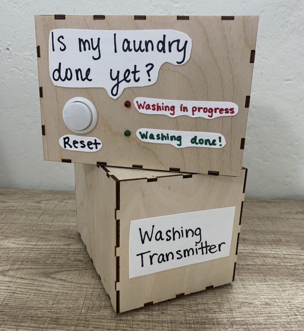
This device tells you when your washing machine is done from two floors away!
Image for scale
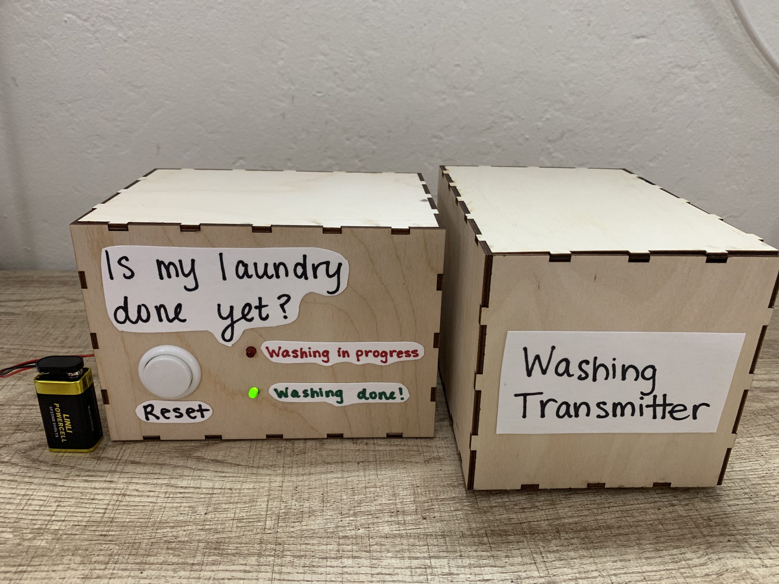
Overall image next to a 9v battery to show scale
Featured details
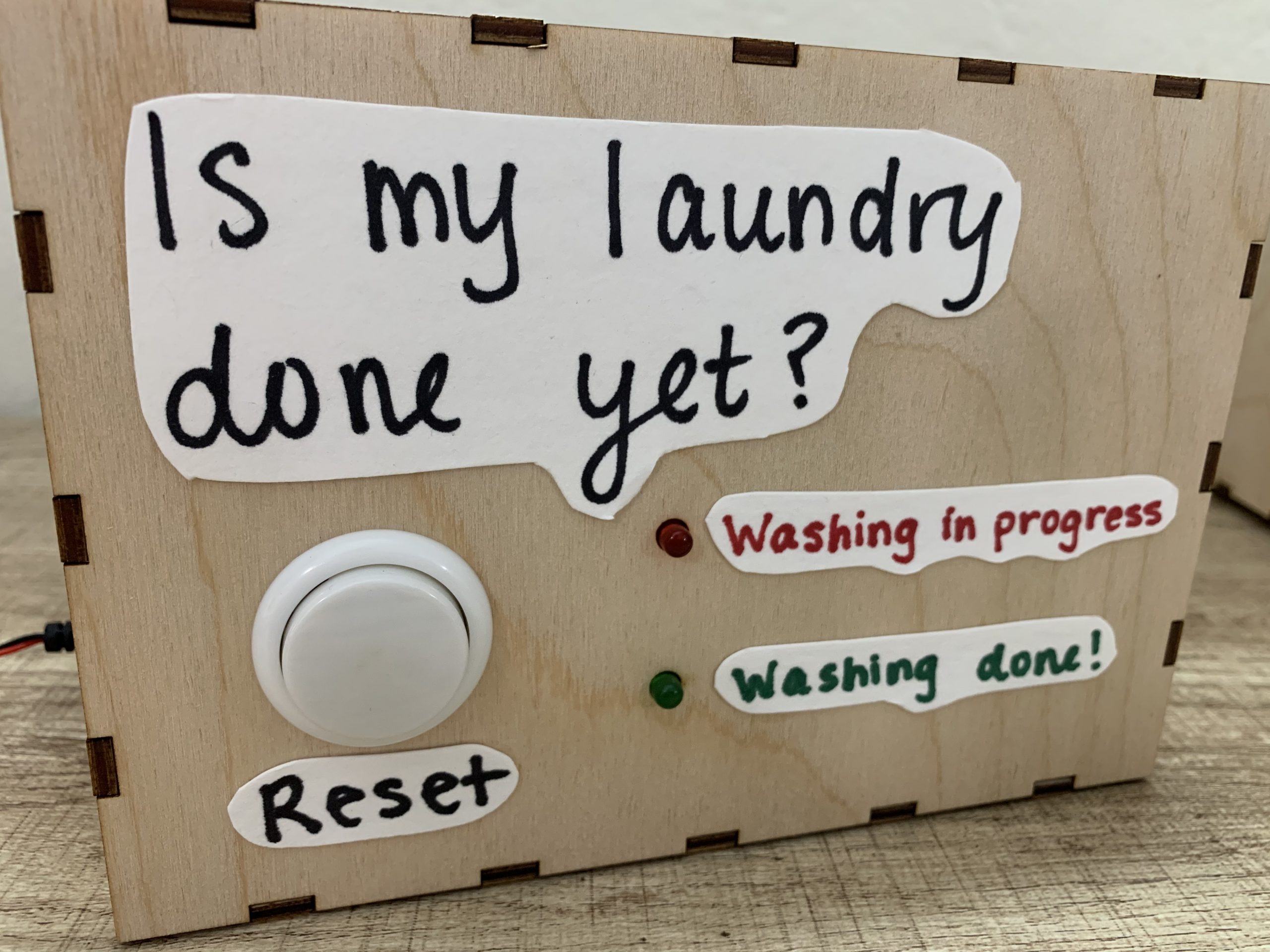
The user interface on the receiving box with panel mounting for the button and LEDs
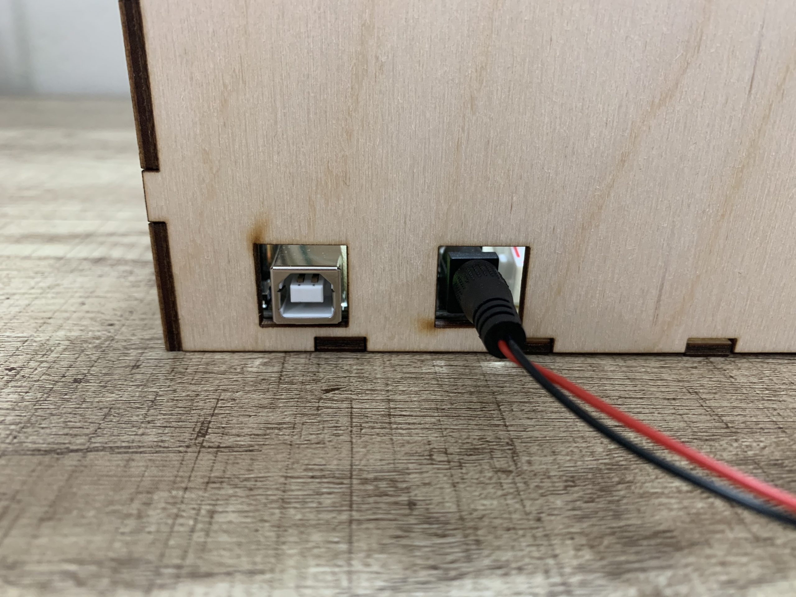
The cut outs in the boxes allow for easy power plug in without opening them
How the device works
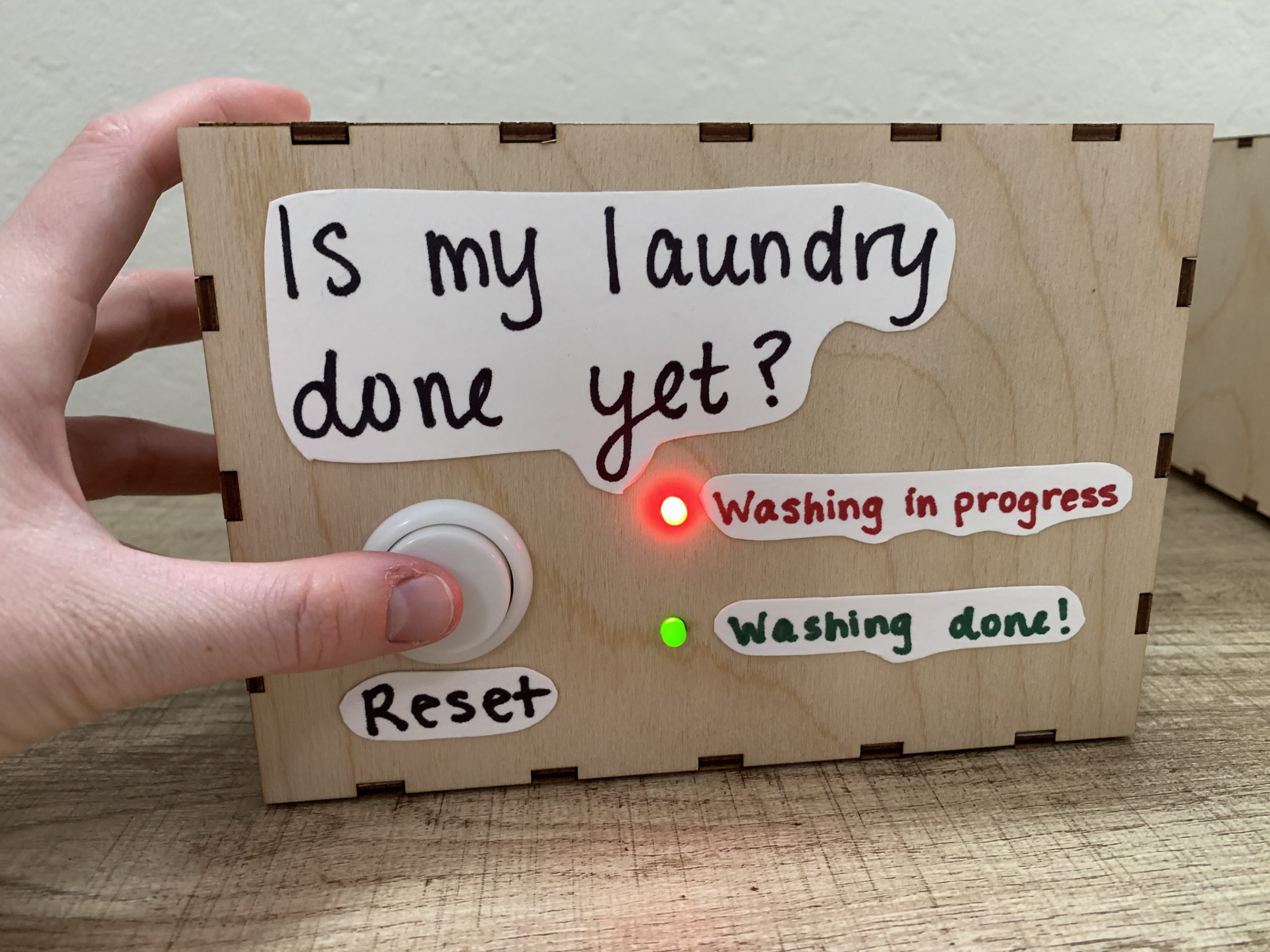
The button resets the cycle and both lights turn on to indicate the resetting
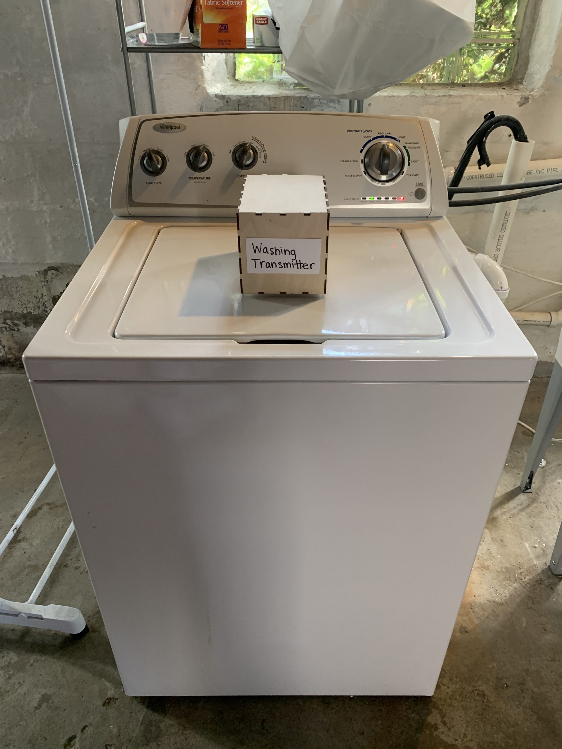
The transmitting box is placed on the washing machine (magnets on the bottom keep it in place) to detect motion
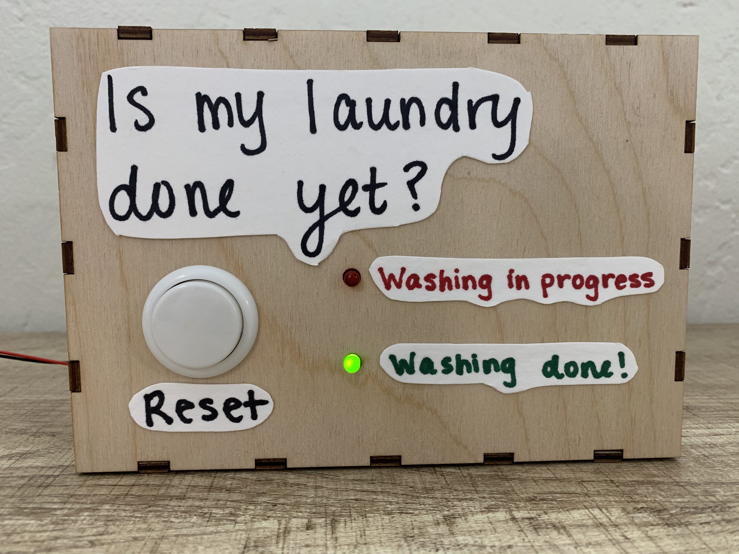
The green light turns on when the washing machine is done moving
Process Images and Review
Below is my original sketch ideation for the project. It is much simpler than what I ended up with, specifically in terms of the user interface. In early ideation, I had vague ideas of what I would want to include in the UX, but I did not formally decide until I was actively working on the prototype.
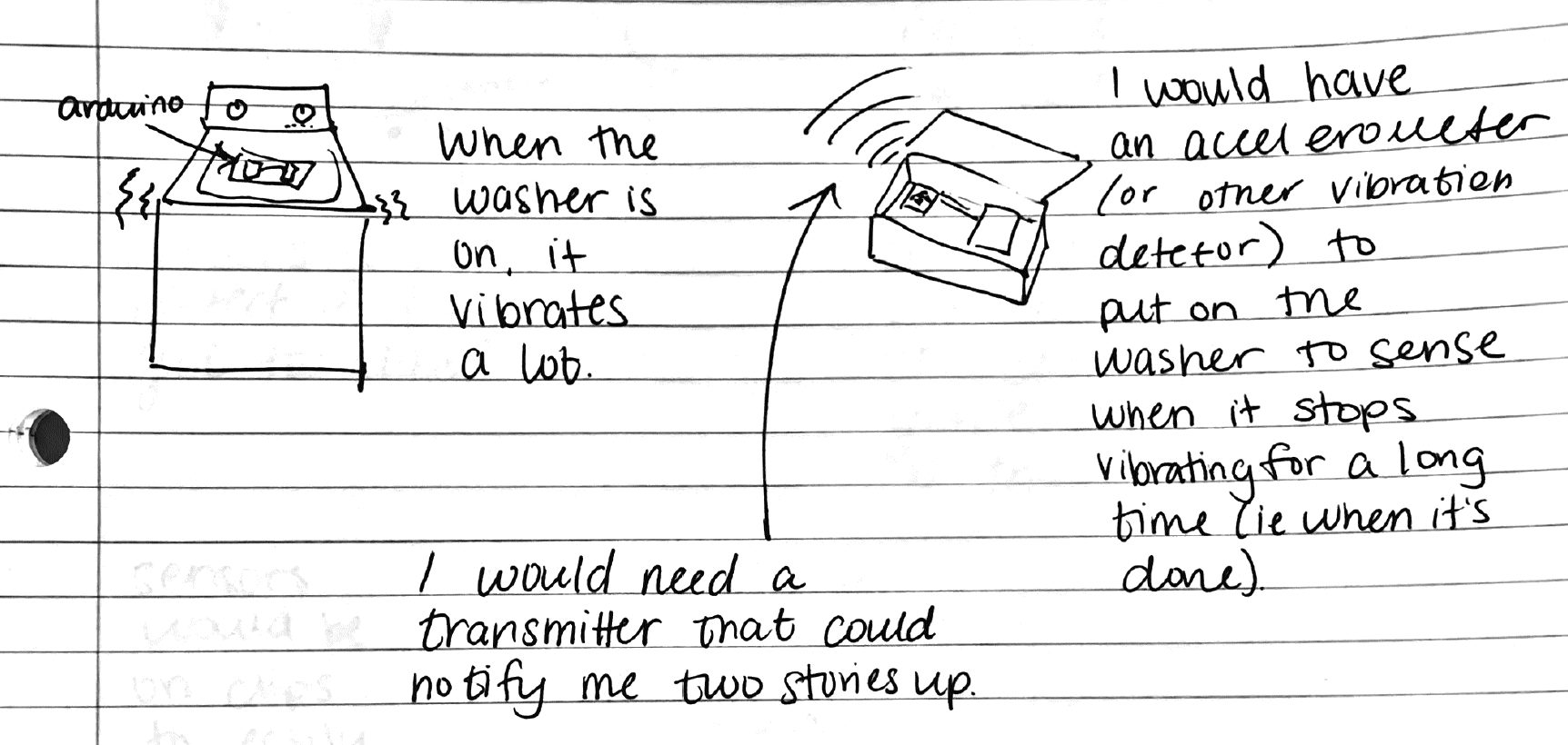
Early ideation sketching
I had a few decision points along my process that affected the outcome of my project. One idea that I tried to implement was including a yellow LED that would be an intermediate state between fully on and fully off. The idea was that the device could provide the user with more information about the washing cycle than just on or off. After lots of trial and error, I did not end up implementing this feature because I was not able to get it working in the code.
Another key point in my project was analyzing the signal from the accelerometer. My original idea was to look at the absolute value of all three axes, to be able to detect any motion in any direction. This proved challenging because I was using the squared function incorrectly in C and was getting very large and meaningless values out of it. After getting help from my instructor, Robert Zacharias, I realized that I did not need to use all three axes, and could get accurate motion detection while only analyzing the x axis data. This simplified my code and math a lot and led me to implement a new method for motion detection: every 1 second, the min and max of the x value is recorded, and if the difference between them is greater than some threshold, then the machine is determined to be moving. Using this method greatly helped me because it created a way for me to tune the sensitivity of the motion detection.
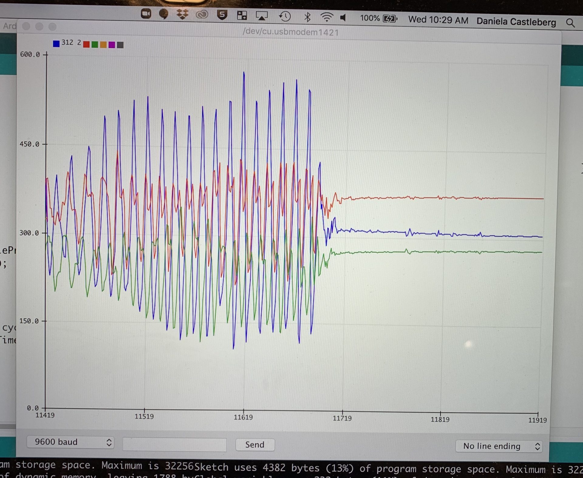
Looking at the serial plotter to see how the x, y, z values changed and determine which single axis would be best for my application
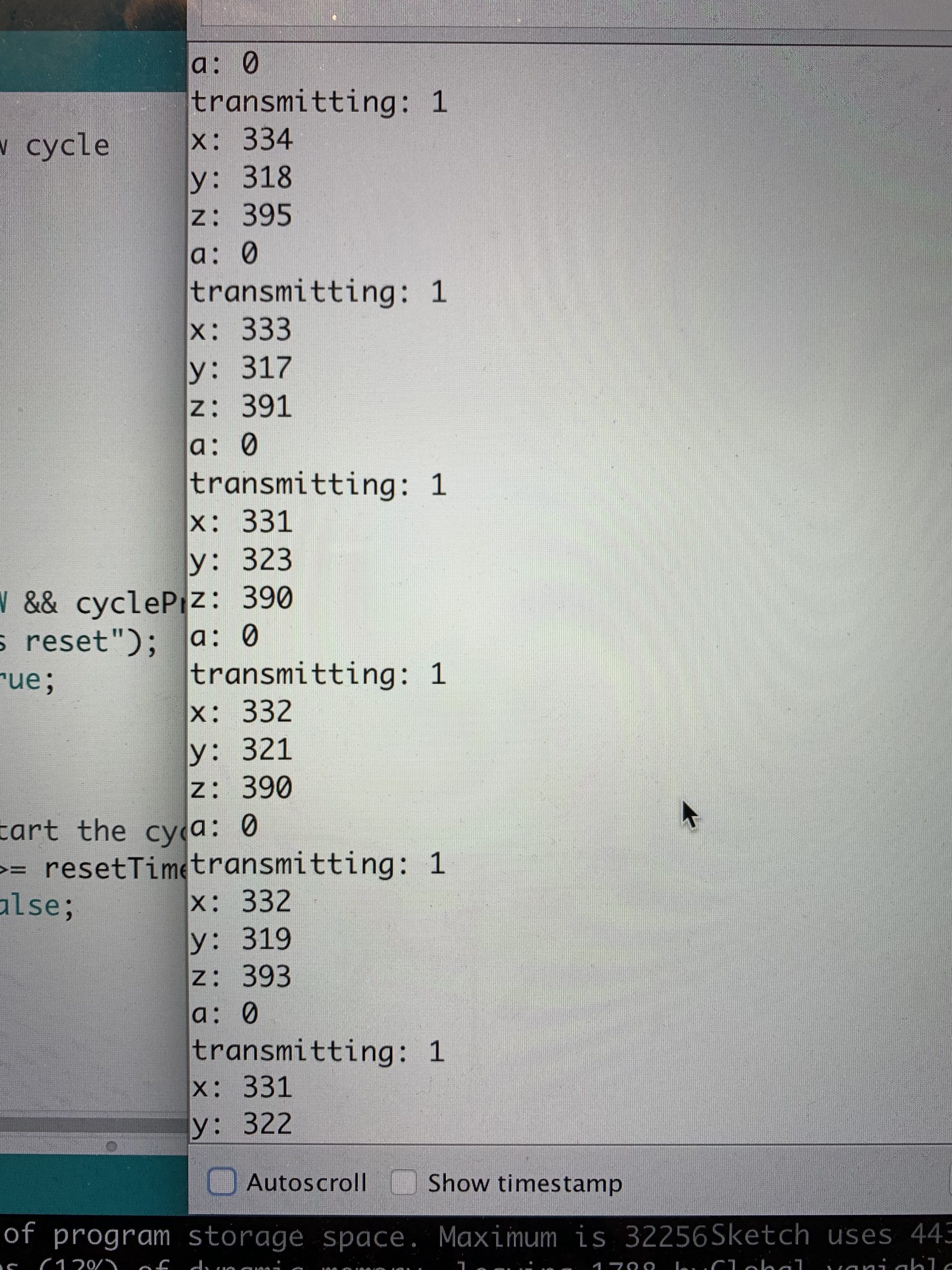
Using the serial monitor to look at accelerometer values and absolute value before changing method
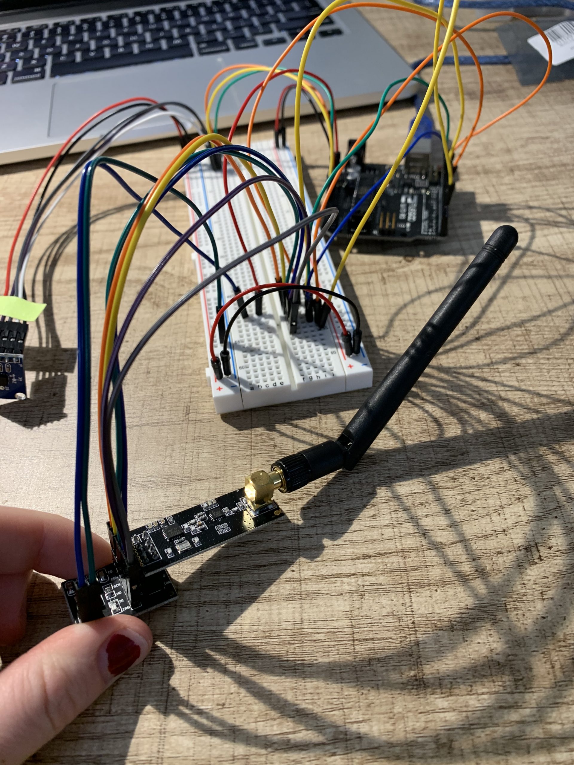
Testing my original radio modules
Discussion
During the in class critique, I got a lot of valuable feedback from my peers. Two points of feedback that I want to highlight are the following:
- “It might not be too complicated to make this smaller, more compact. Still, for user interface purposes, the size makes sense since you have the arcade button and the large font-sized labels.”
- “Really good use of a new component and I like how you integrated two arduinos together.”
I really appreciate the comment on how to improve the project. I agree that the boxes themselves could be made smaller because there was plenty of empty space inside both the transmitter and receiver. However, I also agree that on the receiving end, the size of the box is useful for creating the effective user interface. If I were to create a second iteration of the project I would likely make the transmitting box much smaller so it could be transported to the washing machine more easily and sit more inconspicuously on top. Another change I would make would be to add a buzzer indicator in addition to the green light to better get the attention of the user. Despite these ideas for improvement, I am not planning to create a second iteration. My current design works as intended, and it would be too difficult to fabricate given the limited access to MakerSpaces on campus at the moment. I am very satisfied with how the project turned out and I even exceeded my original vision in terms of aesthetics. My final project includes panel mounting for the button and LEDs which is something I had not planned for originally. Overall, I am glad I pushed myself to create something that is both functional and aesthetically pleasing.
It’s also great to hear positive comments! It was a challenge to incorporate the radio modules because they were something I had never used before, but I now have a new skill and experience with a multi arduino project. I did make some mistakes along the way such as frying my original radio modules. I was able to get new radio modules (which I did not fry!) and they had a good enough range to be picked up from the basement to the second floor of my building.
One unexpected challenge during my project was due to having two arduinos and two different sets of code. As I was adding new complexity to my project, I found that I forgot exactly what data I was sending through the radio, and which end (transmitting or receiving) was actually analyzing the data. In the future I plan on making my code cleaner as I go and trying to write more pseudo code before jumping straight in.
Technical Information
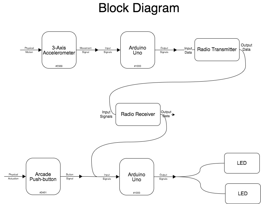
Functional Block Diagram
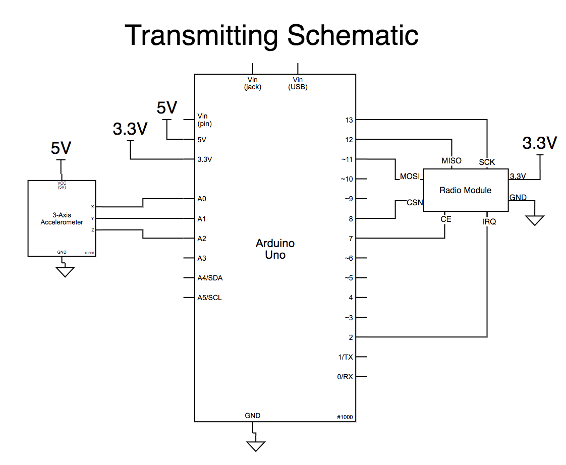
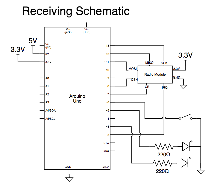
Schematics
Code
/* Washing Machine Project Transmitting File
   By Daniela Castleberg
   Last Updated: 04/09/2021

   This project helps notify someone when their laundry
   is done from two floors away! This file is only for the
   transmitting arduino, you will need both files for
   the project to work in it's entirety.

   Necessary components for this file:
   1 arduino uno
   1 accelerometer
   1 radio NRF24L01 modules

   Pin mapping:
   Arduino pin | type   | description
   ------------|--------|-------------

   TRANSMITTING ARDUINO
   A0            input    accelerometer x
   A1            input    accelerometer y
   A2            input    accelerometer z

   RADIO MAPPING
   radio pin    Arduino Uno pin
   VCC          3.3V
   GND          GND
   CE           7
   CSN          8
   MOSI         11
   MISO         12
   SCK          13

   radio code modified from code by: Robert Zacharias, Alton Olson, Vicky Zhou, Seema Kamath
*/

/////////////////////////////
//        LIBRARIES        //
/////////////////////////////
#include <SPI.h>
#include <nRF24L01.h>
#include <RF24.h>


/////////////////////////////
// ACCELEROMETER VARIABLES //
/////////////////////////////
const int XPIN = A0;
const int YPIN = A1;
const int ZPIN = A2;

unsigned long startTime = 0;
int maxTime = 1000; // time period over 1 second
bool timerIsRunning = false;
bool machineIsMoving = false;

// min and max values of accelerometer
int minX = 500; // need to start high so a smaller value will get updated
int maxX = 0;
int rangeX = 5; // this sets the sensitivity of the motion detection


//////////////////////////////////
// TIMER VARIABLES FOR STOPPING //
//////////////////////////////////
bool machinePreviouslyMoving = true; // make sure we don't continually start the timer during prolonged periods of no motion
unsigned long timer = 0;
unsigned long cycleStopTime = 180000; // amount of time to wait between no motion detected and signal being sent (3min)


/////////////////////////////
//      RADIO VARIABLES    //
/////////////////////////////
const int RADIO_CE = 7;
const int RADIO_CSN = 8;
int transmit = 5; // initialize as anything other than 0 or 1
// 0 means no motion and 1 means there is motion

RF24 radio(RADIO_CE, RADIO_CSN);
const byte address[6] = "00001";


/////////////////////////////
//          SET UP         //
/////////////////////////////
void setup() {
  // set up radio
  radio.begin();
  radio.openWritingPipe(address);
  radio.setPALevel(RF24_PA_HIGH);
  radio.stopListening();

  // set up accelerometer pins
  pinMode(XPIN, INPUT);
  pinMode(YPIN, INPUT);
  pinMode(ZPIN, INPUT);

  Serial.begin(9600);
}


/////////////////////////////
//           LOOP          //
/////////////////////////////
void loop() {

  /////////////////////////////
  // READ CURRENT ACCEL DATA //
  /////////////////////////////
  int x = analogRead(XPIN);
  int y = analogRead(YPIN);
  int z = analogRead(ZPIN);


  ///////////////////////////////////////////////////////////
  // IF THE MACHINE ISNT MOVING, BEGIN TIMING FOR SHUT DOWN//
  ///////////////////////////////////////////////////////////
  if (machineIsMoving == false && machinePreviouslyMoving == true) {
    machinePreviouslyMoving = false;
    timer = millis();  // if no motion is detected, start the timer
  }
  else if (machineIsMoving == false && machinePreviouslyMoving == false) {
    ; // do nothing
  }
  else {
    timer = 0;  // if machine is moving reset timer to 0
    machinePreviouslyMoving = true;
    transmit = 1;
  }


  ////////////////////////////////////////
  // DETERMINE IF THE MACHINE IS MOVING //
  ////////////////////////////////////////
  // if timer is not running, start the timer
  if (timerIsRunning == false) {
    startTime = millis();
    timerIsRunning = true;
    machineIsMoving = false;
  }

  // if timer is running, start taking accelerometer values
  if (timerIsRunning) {
    accelerometerMath(x);
  }

  // if timer >= 1sec reset timer, analyze values, reset values
  if (millis() - startTime >= maxTime) {
    startTime = millis();
    if (maxX - minX >= rangeX) {
      machineIsMoving = true;
    }
    else {
      machineIsMoving = false;
    }
    minX = 500;
    maxX = 0;
  }


  ////////////////////////////////////////
  //            TRANSMIT DATA           //
  ////////////////////////////////////////

  // set transmit variable based on whether the machine is moving or not
  if (machineIsMoving) {
    transmit = 1; // machine moving
  }
  else {
    if (millis() - timer >= cycleStopTime && timer != 0) { // check if it's been longer than the timeout
      transmit = 0; // machine not moving
    }
  }

  int reading[1] = {  // place transmitting value into an array for radio
    transmit
  };


  radio.write(&reading, sizeof(reading)); // send data through radio
  delay(10);
}


////////////////////////////////////////
//              FUNCTIONS             //
////////////////////////////////////////
// function to update min and max readings from accelerometer
void accelerometerMath(int currReading) {
  if (currReading < minX) {
    minX = currReading;
  }
  else if (currReading > maxX) {
    maxX = currReading;
  }
}
/* Washing Machine Project Receiving File
   By Daniela Castleberg
   Last Updated: 04/09/2021

   This project helps notify someone when their laundry
   is done from two floors away! This file is only for the
   recieving arduino, you will need both files for
   the project to work in it's entirety.

   Necessary components for this file:
   1 arduino uno
   1 radio NRF24L01 module
   1 arcade button
   2 LEDs (different colors)

   Pin mapping:
   Arduino pin | type   | description
   ------------|--------|-------------

   RECEIVING ARDUINO
   6             input    Reset button
   5             output   green LED
   3             output   red LED

   RADIO MAPPING FOR BOTH ARDUINOS
   radio pin    Arduino Uno pin
   VCC          3.3V
   GND          GND
   CE           7
   CSN          8
   MOSI         11
   MISO         12
   SCK          13

   radio code modified from code by: Robert Zacharias, Alton Olson, Vicky Zhou, Seema Kamath
*/


/////////////////////////////
//        LIBRARIES        //
/////////////////////////////
#include <SPI.h>
#include <nRF24L01.h>
#include <RF24.h>


/////////////////////////////
//           LEDs          //
/////////////////////////////
const int RED = 3;
const int GREEN = 5;

//////////////////////////////////
//        TIMER VARIABLES       //
//////////////////////////////////
int readVal = 0;
bool newCycle = true;
bool resetButtonState;
bool cyclePreviouslyReset = false;
unsigned long resetTimer = 0;
unsigned long resetTimeout = 3000;


/////////////////////////////
//      RADIO VARIABLES    //
/////////////////////////////
const int RADIO_CE_PIN = 7;
const int RADIO_CSN_PIN = 8;
const int BUTTON = 6;

RF24 radio(RADIO_CE_PIN, RADIO_CSN_PIN);
const byte address[6] = "00001";


/////////////////////////////
//          SET UP         //
/////////////////////////////
void setup() {
  Serial.begin(9600);

  radio.begin();
  radio.openReadingPipe(0, address);
  radio.setPALevel(RF24_PA_HIGH);
  radio.startListening();

  pinMode(BUTTON, INPUT_PULLUP);
  pinMode(GREEN, OUTPUT);
  pinMode(RED, OUTPUT);

}


/////////////////////////////
//           LOOP          //
/////////////////////////////
void loop() {

  // read reset button value
  int resetButton = digitalRead(BUTTON);


  /////////////////////////////
  //    RECEIVE RADIO DATA   //
  /////////////////////////////
  if (radio.available()) {
    int readVal;
    radio.read(&readVal, sizeof(readVal));
    Serial.println(readVal); // print out what the radio is receiving

    if (readVal == 0 && newCycle) { // washing cycle done loop

      Serial.println("Washing Done!"); // print for debugging

      digitalWrite(GREEN, HIGH); // Green LED on to signal washing done
      digitalWrite(RED, LOW);

      delay(500);

      newCycle = false; // no longer a new cycle because it finished
    }

    else if (readVal == 1 && newCycle) { // washing in progress loop

      Serial.println("Washing In Progress");

      digitalWrite(GREEN, LOW);
      digitalWrite(RED, HIGH); // washing in progress
    }
  }

  /////////////////////////////
  //       RESET BUTTON      //
  /////////////////////////////

  // debouncing to eliminate noise
  if (resetButton == LOW) {
    delay(3);
    resetButtonState = LOW;
  }
  else {
    resetButtonState = HIGH;
  }

  // resetting the cycle
  if (resetButtonState == LOW && cyclePreviouslyReset == false) {

    Serial.println("Cycle was reset"); // Serial print for debugging

    cyclePreviouslyReset = true; // loop guard to prevent resetting again immediately
    resetTimer = millis(); // start the reset timer

    digitalWrite(GREEN, HIGH); // turn on both LEDs
    digitalWrite(RED, HIGH);
    delay(500);
  }

  // wait before you can restart the cycle again
  if (millis() - resetTimer >= resetTimeout && cyclePreviouslyReset) {

    cyclePreviouslyReset = false;
    newCycle = true; // reset the new cycle boolean

    digitalWrite(GREEN, LOW); // turn off LEDs
    digitalWrite(RED, LOW);
  }

}