The goal of the project was to design an assistive device for someone else. We were to get to know our client and understand where in their life they could benefit from something that we could create. We then kept in contact with them throughout the building process to make sure we were making something that addressed their goals. The notes and insights from the interview can be found here.
What We Built
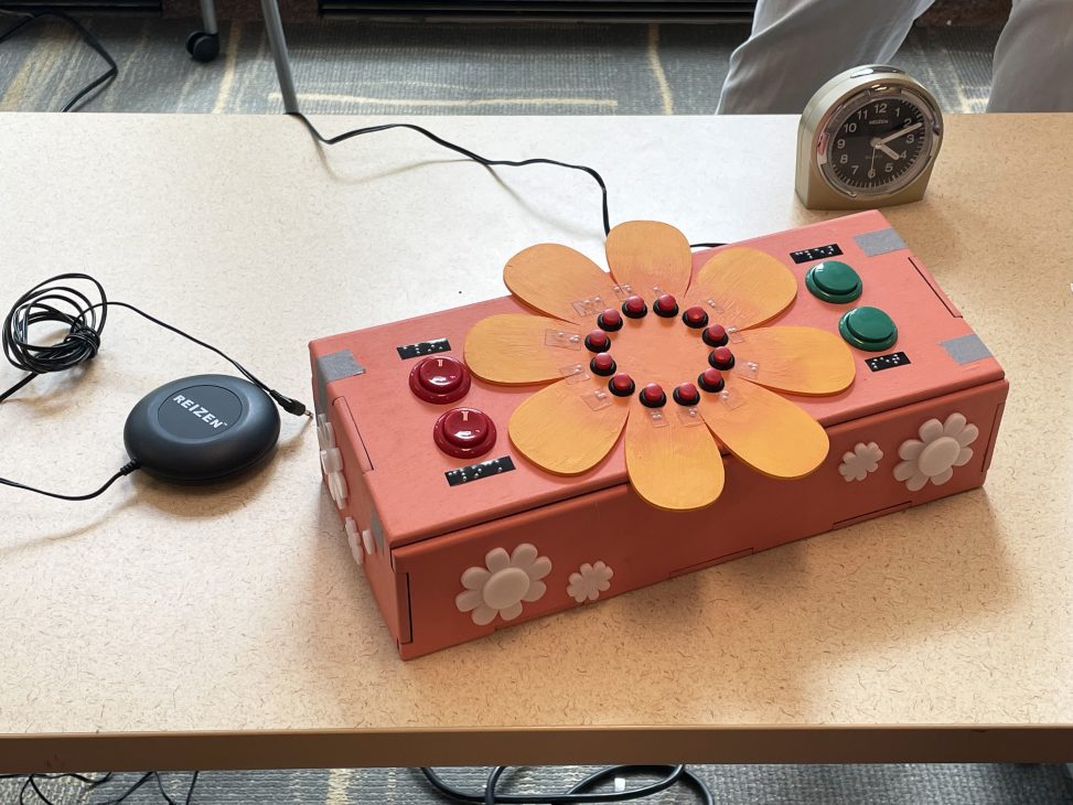
We created a braille alarm clock. The alarm clock is fully functional by someone who is both without sight and hard of hearing. The user can check and reset the current time, as well as set the time for when they’d like their alarm to go off, and it will reliably do so.

Final clock with bed shaker and original alarm clock on presentation day
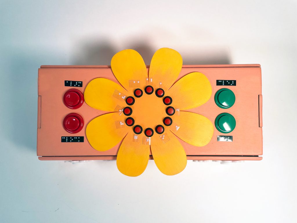
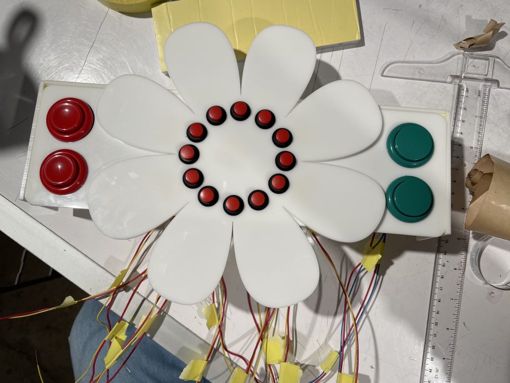
Top interface of clock with 12 red buttons in a circle for the clock, and 2 red buttons on the left (alarm and clock), and 2 green buttons (set and clear)
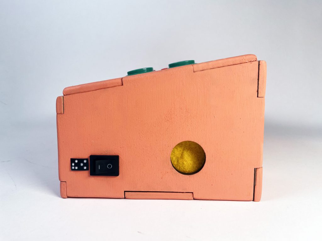
Right side of prototype with solenoid and rocker switch
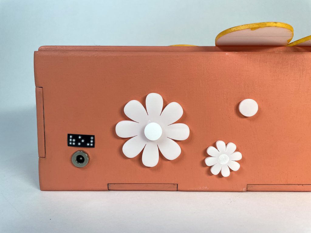
Back of clock with acrylic flower details and power plug
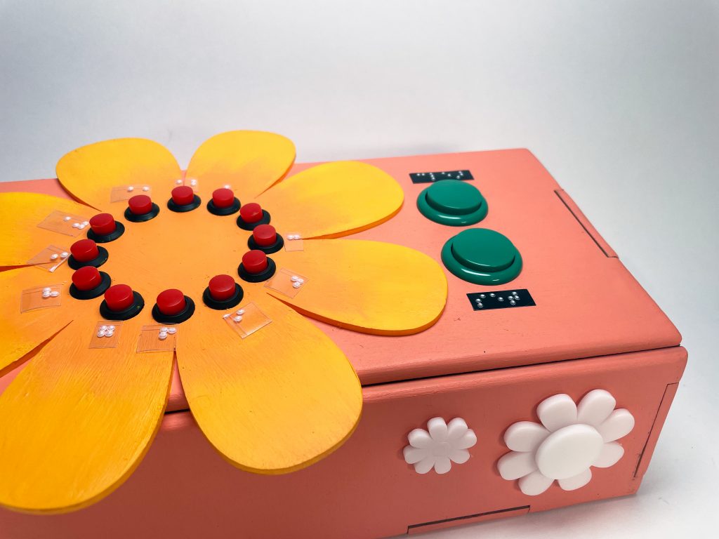
Additional flower acrylic details at the front
Alycia testing out our final device. (Seated to the right of the a table is Alycia, a middle-aged woman with long hair. She is pressing buttons on a pink box that acts as a clock with brailled on it)
Narrative Sketch
Alicia has a big day tomorrow and wants to get an early start in the morning. She goes to her alarm clock, presses the arcade button marked Alarm and then shifts her hand to the clock buttons. She presses the fifth button, and then the sixth button: 5:30.She then presses a different button market Set. Just to double check that she didn’t make a mistake, she presses the Alarm button once more. Now the exciting part… she shifts her hand to the right wall of the clock, feeling for a circle opening with felt under it. Two of her fingers lightly rest on the felt and she waits. Tap, Tap, Tap, Tap, Tap. 5. There’s a short pause. Tap, Tap, Tap. 3. There’s a much pause. 0. A quick Tap-Tap. Knowing that the end of the sequence is always marked by the Tap-Tap, she goes to bed content.
Come morning time, the bed shaker violently rocks her bed waking her up. She gets out of bed, goes to the alarm clock and switches the switch from ON to OFF. The bed shaker stops immediately. She wants to check the time just to ensure she didn’t miss anything in her day, so she presses Clock and moves her fingers to the felt again. 5 taps, 3 taps, and 1 tap. 5:31am. She nods with satisfaction and starts her day.
How We Got Here (Prototype and Process)
This prototype was designed to help answer the design question: How do we make an alarm clock for a blind person that is hard of hearing?
Prototype
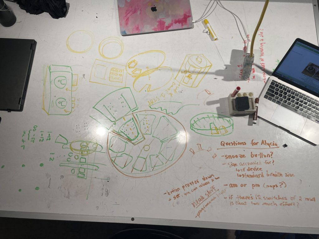
First meeting discussion possible ideas
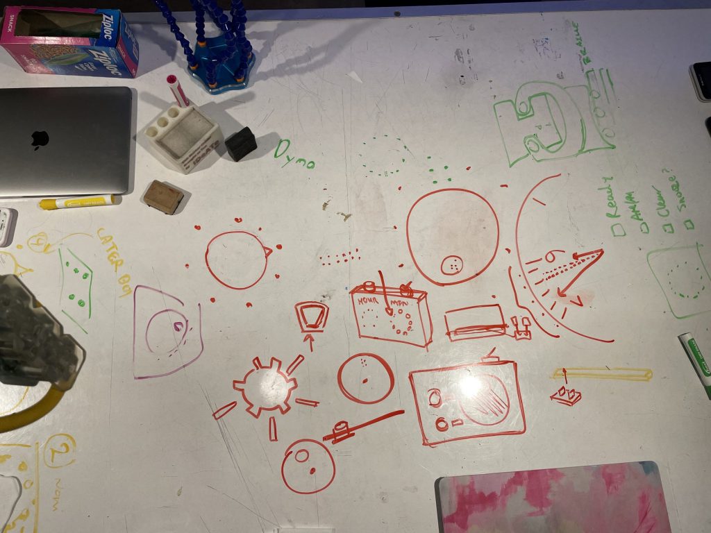
Second meeting discussing clock ideas
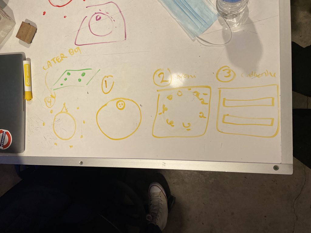
Final 3 ideas for prototyping
Prototype 1: Two clocks where each number is a button. The first clock would be for setting the hours, and the second clock would be for setting the minutes.
Prototype 2: A finger slider, where you put your finger on a slider and the top of your finger would slide across different braille numbers. When you got to the number you wanted first, you would press set, and that would set the hours. Then for the minutes, you would slide to the number you wanted and that would set the minutes.
Prototype 3: The third idea is similar to a rotary phone where you would put your finger in a small hole and circle around all the numbers to the number you were looking for. In each number spot would be braille that the user can read, and they would use the rotary system to set the hours and then minutes of their alarm.
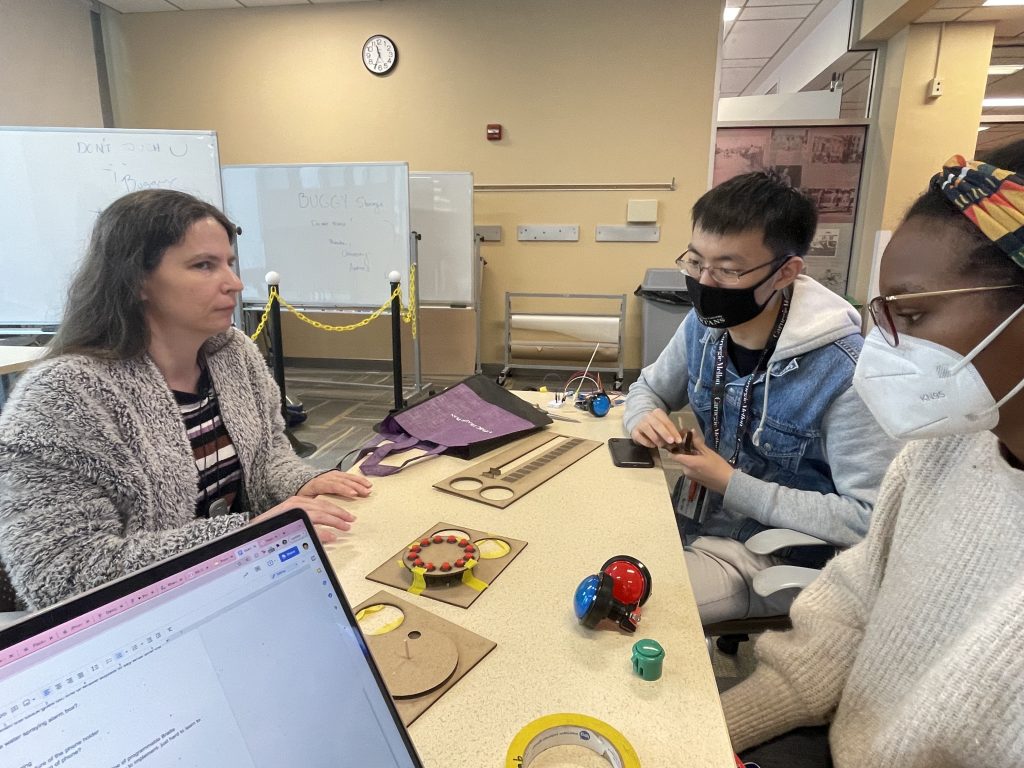
Showing Alycia the prototypes on prototype day
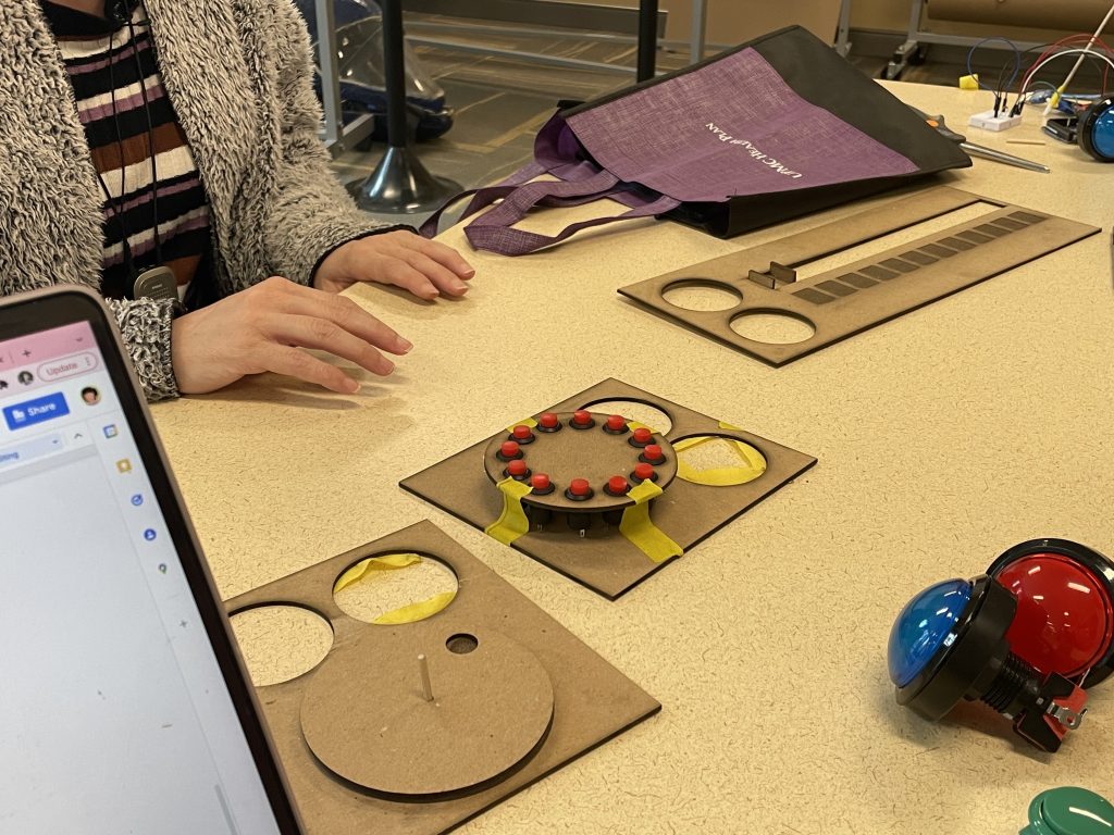
Our 3 prototype interfaces
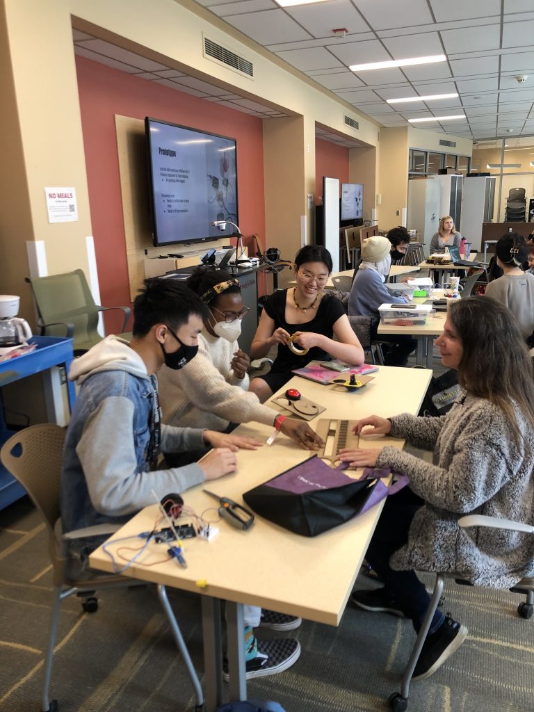
testing prototypes with Alycia
Alycia showing us how to make braille on dymo tape
(Alycia is using a poking device and a braille grid to press indentations onto sticky tape)
All of our prototypes were feasible, yet how we moved forward was solely to the discretion of our client and what her personal preference was in terms of the alarm. She chose Prototype 1, where the interface is all buttons in a circle.
We were a bit surprised that the client chose the option she did. When she went over her reasoning, she explained that practicality and ease-of-use in the long term were her main decision factors. The other ideas were fun and exciting, but there’s much less that could go wrong with simple buttons. She also gave feedback that was eye-opening in the sense that we were underestimating her skills ability to a great extent. Things such as only needing one button clock interface and not two, and needing less braille options, her intuit knowledge that could help her use the alarm with ease. Initially when designing and speaking amongst each other, we were approaching the prototype as if we had just lost our vision and were encountering the world for the first time. However, after talking with Alyicia, we were able to revise our prototypes and make them not only braille friendly, but also extremely intuitive to her needs.
Feedback we took from the critique was to make it only one clock interface, as well as to change the button size. Alicia opted for smaller buttons around the clock as those would decrease the overall size of the alarm. She also mentioned the need for there to be ample space around each button as that would ensure there was enough room for her dymo tape to stick on. Thus, we made sure to account for the braille attachments and their length and width in each button design. She also told us she had no need for a Snooze button, nor did she need an option to set any time more than the multiples of five. This type of feedback was pivotal to our further discussion of how to implement the alarm clock successfully.
Something we hadn’t even considered before she brought it up, was being able to tell the normal time of the day using the alarm clock. She informed us this was normal practice on her existing braille alarm clock that didn’t work that well. Initially we chose not to focus on this as the clock module should have been able to reliably keep the time and there would be no reason to doubt it. However, after much discussion as a team and with our professor, we reimplemented it as a feature.
Process
Deciding on how to improve prototype after showing to Alycia
Final interface design for the clock
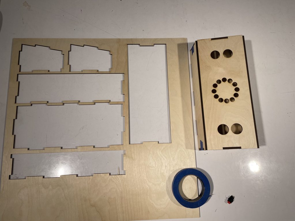
Lasercut plywood to build clock
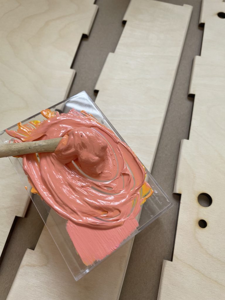
Painting the plywood
The programmable portion of the alarm clock was based on a finite state machine, a concept that David was familiar with from his ECE studies. This style of design was chosen because an alarm clock enters through many states during its usage, and transitioning between states based on inputs (and generating outputs at the right time) are all central ideas to an FSM. The final product ended up with seven states, and it worked extremely well- it allowed for coding details much easier, as it helped partition up the overall complicated structure into smaller, more manageable pieces. That being said, coding did have its fair share of difficulties. Converting a button into a toggle-able input was surprisingly complex; it involved debouncing a button to prevent erroneous multiple readings upon press and release of the button, as well as checking to make sure when a button is pressed and held (and not causing the incorrect interpretation of multiple button presses). The code also involved understanding a RTC (real-time clock) library, which had its own hidden difficulties (we had spent nearly an hour panicking as to why the clock was not working until we realized we hadn’t written the code to actually START the clock!). With respect to the Gantt chart, there was some divergence from the original plan, because testing the code proved to be more reliant upon the hardware it worked with- for example, it was impossible to check if anything related to the clock was working if there was no clock module, which we did not receive until much later than anticipated. Nonetheless, the code was still completed and thoroughly debugged.
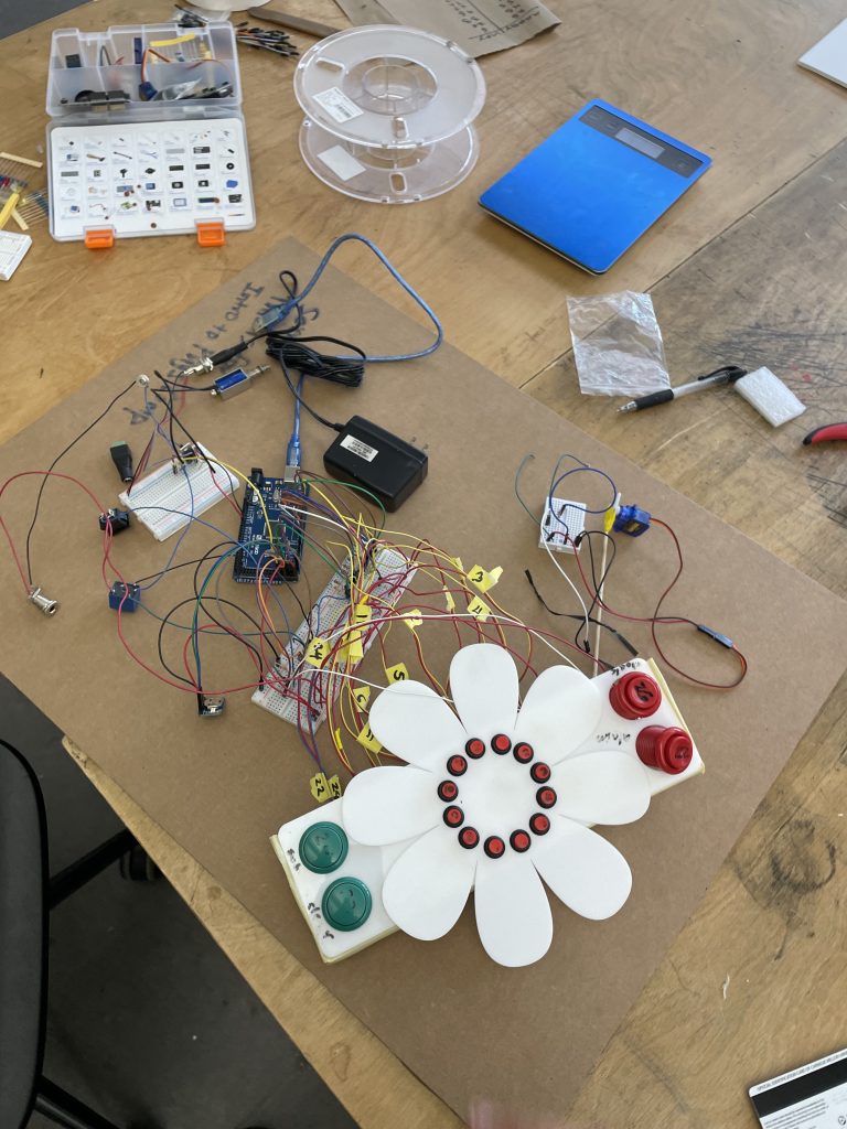
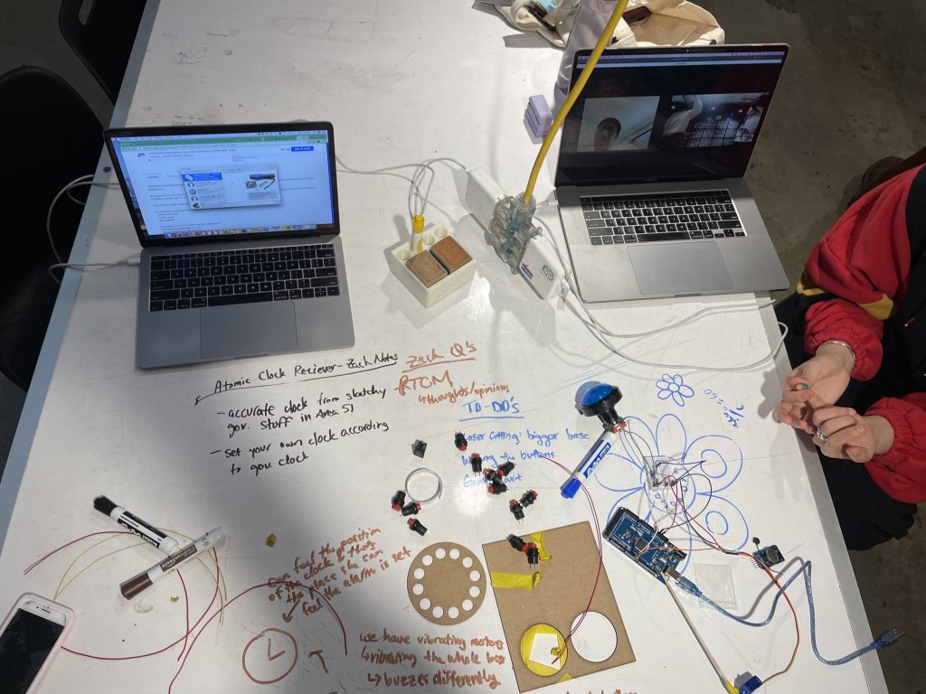
All wiring of the clock
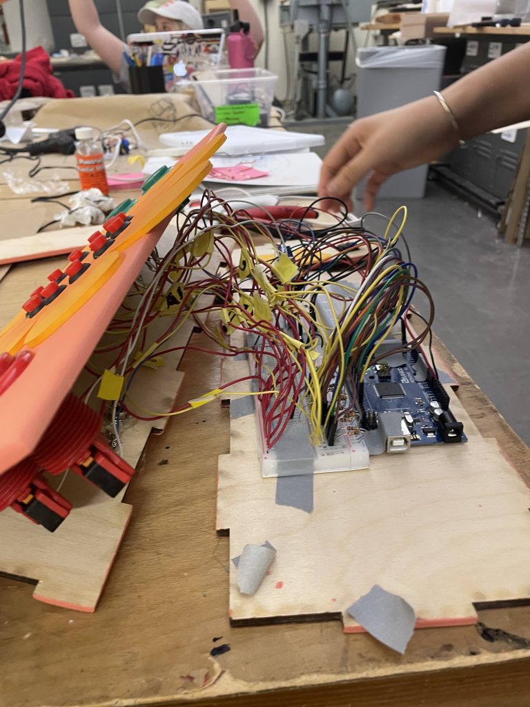
Putting all components into the fingerjoint base
There were a few tricky components to the circuitry, such as the solenoid and the interfacing of the bed shaker and its power supply. The solenoid needed to be powered directly by a 12VDC power supply, yet it had to be controlled by the Arduino; as such, a transistor circuit was used to act as a “switch” that the Arduino could control to allow for power to the solenoid. Interfacing with the bed shaker proved to be very complicated, due to the strange peculiarity that it ran off of 9VAC. Creating a switch for 9V, being alternating current as well, was rather difficult, since that implied it would require a power supply that could not be unified in any way with the Arduino (unlike the solenoid, whose 12VDC power supply could also be used for the Arduino). Controlling an AC power supply also required the use of a relay, which was in essence, a switch for AC power supplies, similar to the transistor. The relay proved to also be troublesome in that it would draw too much current from the Arduino should it be directly connected, and that meant that another transistor circuit was needed for the relay- in essence, a switch for the switch. It was certainly a confusing set of circuitry- a memorable moment was when the transistor was actually fried due to an incorrect wiring, which then caused subsequent correct wirings to not work as well.
Conclusions and Lessons Learned
We learned throughout the process that planning was very important to ensure that we could get all the different parts done well. Since we each had different responsibilities, it was important that we communicated our schedules well and adjusted our work plan as needed so that everyone in the group could work on their responsibilities. Especially for our code-heavy project, we found that it was always better to test early and test more. There would often be small edge cases that would mess with how our clock worked. Changes also needed to be made physically, such as adding another button or changing where the buttons were placed, which would help make using the device easier for Alycia. Additionally, we realized that we could make the best device only if we knew what the client actually needed and wanted. Rather than making assumptions, we always made sure to ask Alycia on what she thought would work the best for her as well as what she wanted from the project. There were times when her responses reassured our progress, and other where we were surprised by what she said and would have to rethink our ideas. In the end, we were grateful that Alycia was very cooperative and responsive to us during this project as we were able to produce a product that she liked as well.
A common, but important piece of advice that was given was that “Though it’s for a blind person, for presentations sake, there could have been some visual labels.” This would allow for those who were NOT Alycia (eg. caretakers, friends, etc.) to be able to understand what was what on the clock. This would be a simple change, but extremely necessary, since as of now, we only know which buttons are what simply because we are the creators. There were also comments on the alarm clock having “other features that many clocks have (i.e., snooze).” This was also a fair point, and was considered by our team; given more time, this definitely could have been done. While we considered the situation of having too many inputs and causing confusion rather than more features, simple thoughts like “Different shape on the “12” button” to help find/distinguish the clock buttons easier would be useful and helpful to implement.
Technical Details
Schematic and Block Diagram

Code
/* Project Title: Tactile Alarm Clock
 * Creator: David Wu, Noni Shelton, and Catherine Liu
 *
 * This code is similar to a finite state machine for
 * an alarm clock. There are 12 button inputs for the 12
 * numbers on the clock. There are 4 other button inputs
 * for miscellaneous purposes, being the alarm, clock,
 * set, and clear buttons. The 16 button inputs are each
 * involved in 2 arrays to facilitate checking for button
 * presses and button holding. An on/off input is used to
 * determine if the alarm is turned on or not. An output signal
 * to a solenoid allows it to tap the time in an specified,
 * encoded manner. The code outputs its alarm signal at a certain
 * pin, and for this project, this is intended to connect the
 * bed shaker to its power supply.
 *
 * Pin Mapping:
 * Clock 12 : 12    Clock 6  : 6
 * Clock 1  : 13    Clock 7  : 7
 * Clock 2  : 2     Clock 8  : 8
 * Clock 3  : 3     Clock 9  : 9
 * Clock 4  : 4     Clock 10 : 10
 * Clock 5  : 5     Clock 11 : 11
 * Doing Alarm               : 27
 * Doing Clock               : 26
 * Set                       : 24
 * Clear                     : 22
 * Alarm On/Off              : 28
 * Solenoid                  : 30
 * Alarm output (bed shaker) : 33
 *
 */

#include <Wire.h>
#include "RTClib.h"

RTC_DS3231 rtc;

// clock 12 inputs
const int CLOCKPIN0 = 12;
const int CLOCKPIN1 = 13;
const int CLOCKPIN2 = 2;
const int CLOCKPIN3 = 3;
const int CLOCKPIN4 = 4;
const int CLOCKPIN5 = 5;
const int CLOCKPIN6 = 6;
const int CLOCKPIN7 = 7;
const int CLOCKPIN8 = 8;
const int CLOCKPIN9 = 9;
const int CLOCKPIN10 = 10;
const int CLOCKPIN11 = 11;

// the miscellaneous buttons
const int DOING_ALARMPIN = 27;
const int DOING_CLOCKPIN = 26;
const int SETPIN = 24;
const int CLEARPIN = 22;

// alarm on/off
const int ON_OFFPIN = 28;

// outputs
const int SOLEPIN = 30;
const int BEDSHAKERPIN = 33;

// state management
int currState = 0;
int nextState = 0;
const int defaultState = 0;
const int alarmState = 1;
const int clockState = 2;
const int setAlarmHourState = 3;
const int setClockHourState = 4;
const int setAlarmMinState = 5;
const int setClockMinState = 6;
const int alarmTriggered = 7;

// clock 12 inputs
int clockInput[12];
int clockPressed[12];

// the miscellaneous buttons
// misc inputs: doing_alarm, doing_clock, set, clear
int miscInput[4];
int miscPressed[4];

// alarm on/off
bool isOn = true;

// time management
// arbitrary default setting when clock is first turned on
const int DEFAULT_HOUR = 7;
int alarmHour = DEFAULT_HOUR;
int alarmMin = 0;
int tempHour = DEFAULT_HOUR;
int tempMin = 0;

void setup() {
  pinMode(CLOCKPIN0, INPUT);
  pinMode(CLOCKPIN1, INPUT);
  pinMode(CLOCKPIN2, INPUT);
  pinMode(CLOCKPIN3, INPUT);
  pinMode(CLOCKPIN4, INPUT);
  pinMode(CLOCKPIN5, INPUT);
  pinMode(CLOCKPIN6, INPUT);
  pinMode(CLOCKPIN7, INPUT);
  pinMode(CLOCKPIN8, INPUT);
  pinMode(CLOCKPIN9, INPUT);
  pinMode(CLOCKPIN10, INPUT);
  pinMode(CLOCKPIN11, INPUT);
  pinMode(DOING_ALARMPIN, INPUT);
  pinMode(DOING_CLOCKPIN, INPUT);
  pinMode(SETPIN, INPUT);
  pinMode(CLEARPIN, INPUT);
  pinMode(ON_OFFPIN, INPUT);
  pinMode(SOLEPIN, OUTPUT);
  pinMode(BEDSHAKERPIN, OUTPUT);

  // ensure rtc is found and we can start
  if (!rtc.begin()) {
    while (1);
  }

  // initialize an arbitrary time (12:34)
  // rtc.adjust(DateTime(F(__DATE__), F(__TIME__)));
  rtc.adjust(DateTime(2000, 1, 1, 12, 34, 0));
  Serial.begin(9600);
}

void loop() {
  // clock 12 inputs
  clockInput[0] = digitalRead(CLOCKPIN0);
  clockInput[1] = digitalRead(CLOCKPIN1);
  clockInput[2] = digitalRead(CLOCKPIN2);
  clockInput[3] = digitalRead(CLOCKPIN3);
  clockInput[4] = digitalRead(CLOCKPIN4);
  clockInput[5] = digitalRead(CLOCKPIN5);
  clockInput[6] = digitalRead(CLOCKPIN6);
  clockInput[7] = digitalRead(CLOCKPIN7);
  clockInput[8] = digitalRead(CLOCKPIN8);
  clockInput[9] = digitalRead(CLOCKPIN9);
  clockInput[10] = digitalRead(CLOCKPIN10);
  clockInput[11] = digitalRead(CLOCKPIN11);

  // misc inputs: doing_alarm, doing_clock, set, clear
  miscInput[0] = !digitalRead(DOING_ALARMPIN); // normally closed button
  miscInput[1] = !digitalRead(DOING_CLOCKPIN); // normally closed button
  miscInput[2] = digitalRead(SETPIN);
  miscInput[3] = digitalRead(CLEARPIN);

  // alarm on/off
  isOn = digitalRead(ON_OFFPIN);

  // find if/which clockInput was pressed
  int trigClockButton = -1;
  for (int i = 0; i < 12; i++) {
    if (clockInput[i] == 1) {
      trigClockButton = i;
    }
  }

  // find if/which miscInput was pressed
  int trigMiscButton = -1;
  for (int i = 0; i < 4; i++) {
    if (miscInput[i] == 1) {
      trigMiscButton = i;
    }
  }

  // when to start output
  if (isOn) {
    DateTime now = rtc.now();
    if ((convert12Hour(now.hour()) == alarmHour) &&
        (now.minute() == alarmMin)  &&
        (now.second() < 5)) {
       currState = alarmTriggered;
    }
  }

  // figure out next state and output
  if (currState == alarmTriggered) {
    if(!isOn) {
      digitalWrite(BEDSHAKERPIN, LOW);
      nextState = defaultState;
    }
    else {
      digitalWrite(BEDSHAKERPIN, HIGH);
      nextState = alarmTriggered;
    }
  }
  else if (trigMiscButton != -1)
    handlePressedMiscButton(trigMiscButton);
  else if (trigClockButton != -1)
    handlePressedClockButton(trigClockButton);
  else
    nextState = currState;

  // update unpressed buttons
  // when a clockInput is unpressed and was pressed before
  for (int i = 0; i < 12; i++) {
    if (!clockInput[i] && clockPressed[i]) {
      delay(30);
    }
  }
  // when a miscInput is unpressed and was pressed before
  for (int i = 0; i < 4; i++) {
    if (!miscInput[i] && miscPressed[i]) {
      delay(30);
    }
  }

  //update info
  clockPressed[0] = clockInput[0];
  clockPressed[1] = clockInput[1];
  clockPressed[2] = clockInput[2];
  clockPressed[3] = clockInput[3];
  clockPressed[4] = clockInput[4];
  clockPressed[5] = clockInput[5];
  clockPressed[6] = clockInput[6];
  clockPressed[7] = clockInput[7];
  clockPressed[8] = clockInput[8];
  clockPressed[9] = clockInput[9];
  clockPressed[10] = clockInput[10];
  clockPressed[11] = clockInput[11];

  miscPressed[0] = miscInput[0];
  miscPressed[1] = miscInput[1];
  miscPressed[2] = miscInput[2];
  miscPressed[3] = miscInput[3];

  currState = nextState;
}

void handlePressedClockButton (int index) {
  // when the clockInput is pressed and was not pressed before
  if (!clockPressed[index]) {
    delay(30);
    switch (currState) {
      // if alarm is triggered, ignore everything
      case alarmTriggered:
        break;
      case alarmState:
        tempHour = index;
        if (tempHour == 0) tempHour = 12;
        nextState = setAlarmHourState;
        break;
      case clockState:
        tempHour = index;
        if (tempHour == 0) tempHour = 12;
        nextState = setClockHourState;
        break;
      case setAlarmHourState:
        tempMin = index * 5;
        nextState = setAlarmMinState;
        break;
      case setClockHourState:
        tempMin = index * 5;
        nextState = setClockMinState;
        break;
      default:
        nextState = currState;
        break;
    }
  }
}

void handlePressedMiscButton (int index) {
  // misc inputs: doing_alarm, doing_clock, set, clear
  // when the miscInput is pressed and was not pressed before
  if (!miscPressed[index]) {
    delay(30);
    // if alarm is triggered, ignore everything
    if (currState == alarmTriggered) {
      nextState = alarmTriggered;
    }
    // doing_alarm
    else if (index == 0) {
      solenoidTapping(alarmHour, alarmMin);
      nextState = alarmState;
    }
    // doing_clock
    else if (index == 1) {
      DateTime now = rtc.now();
      solenoidTapping(convert12Hour(now.hour()), now.minute());
      nextState = clockState;
    }
    else {
      switch (currState) {
        case alarmState:
        case setAlarmHourState:
          if (index == 2) {
            // not complete inputs
            tempHour = DEFAULT_HOUR;
            tempMin = 0;
            nextState = defaultState;
          }
          else if (index == 3) {
            tempHour = DEFAULT_HOUR;
            tempMin = 0;
            nextState = alarmState;
          }
          break;
        case clockState:
        case setClockHourState:
          if (index == 2) {
            // not complete inputs
            tempHour = DEFAULT_HOUR;
            tempMin = 0;
            nextState = defaultState;
          }
          else if (index == 3) {
            tempHour = DEFAULT_HOUR;
            tempMin = 0;
            nextState = clockState;
          }
          break;
        case setAlarmMinState:
          if (index == 2) {
            alarmHour = tempHour;
            alarmMin = tempMin;
            nextState = defaultState;
          }
          else if (index == 3) {
            tempHour = DEFAULT_HOUR;
            tempMin = 0;
            nextState = alarmState;
          }
          break;
        case setClockMinState:
          if (index == 2) {
            // DateTime(YYYY, M, D, h, m, s)
            rtc.adjust(DateTime(2000, 1, 1, tempHour, tempMin, 0));
            nextState = defaultState;
          }
          else if (index == 3) {
            tempHour = DEFAULT_HOUR;
            tempMin = 0;
            nextState = clockState;
          }
          break;
        default:
          nextState = currState;
          break;
      }
    }
  }
}

// Taps: Hours, Tens place of Mins, Ones place of Mins
// Ex. 9:47 is 9 taps, 4 taps, 7 taps
void solenoidTapping (int timeHour, int timeMinute) {
  for (int i = 0; i < timeHour; i++) {
    digitalWrite(SOLEPIN, HIGH);
    delay(50);
    digitalWrite(SOLEPIN, LOW);
    delay(450);
  }
  delay(2000);
  int minuteTens = timeMinute / 10;
  int minuteOnes = timeMinute % 10;
  for (int i = 0; i < minuteTens; i++) {
    digitalWrite(SOLEPIN, HIGH);
    delay(50);
    digitalWrite(SOLEPIN, LOW);
    delay(450);
  }
  delay(2000);
  for (int i = 0; i < minuteOnes; i++) {
    digitalWrite(SOLEPIN, HIGH);
    delay(50);
    digitalWrite(SOLEPIN, LOW);
    delay(450);
  }
  delay(2000);
  // a quick TAP-TAP to signal done tapping
  digitalWrite(SOLEPIN, HIGH);
  delay(50);
  digitalWrite(SOLEPIN, LOW);
  delay(100);
  digitalWrite(SOLEPIN, HIGH);
  delay(50);
  digitalWrite(SOLEPIN, LOW);
  delay(100);
}

// converts hours from 24-hour format to 12-hour format
int convert12Hour(int timeHour) {
  // later half of day
  if (timeHour > 12)
    return timeHour - 12;
  // midnight
  else if (timeHour == 0)
    return 12;
  else
    return timeHour;
}