The chameleon necklace changes color to match its surroundings, allowing users to match their jewelry to their outfits.
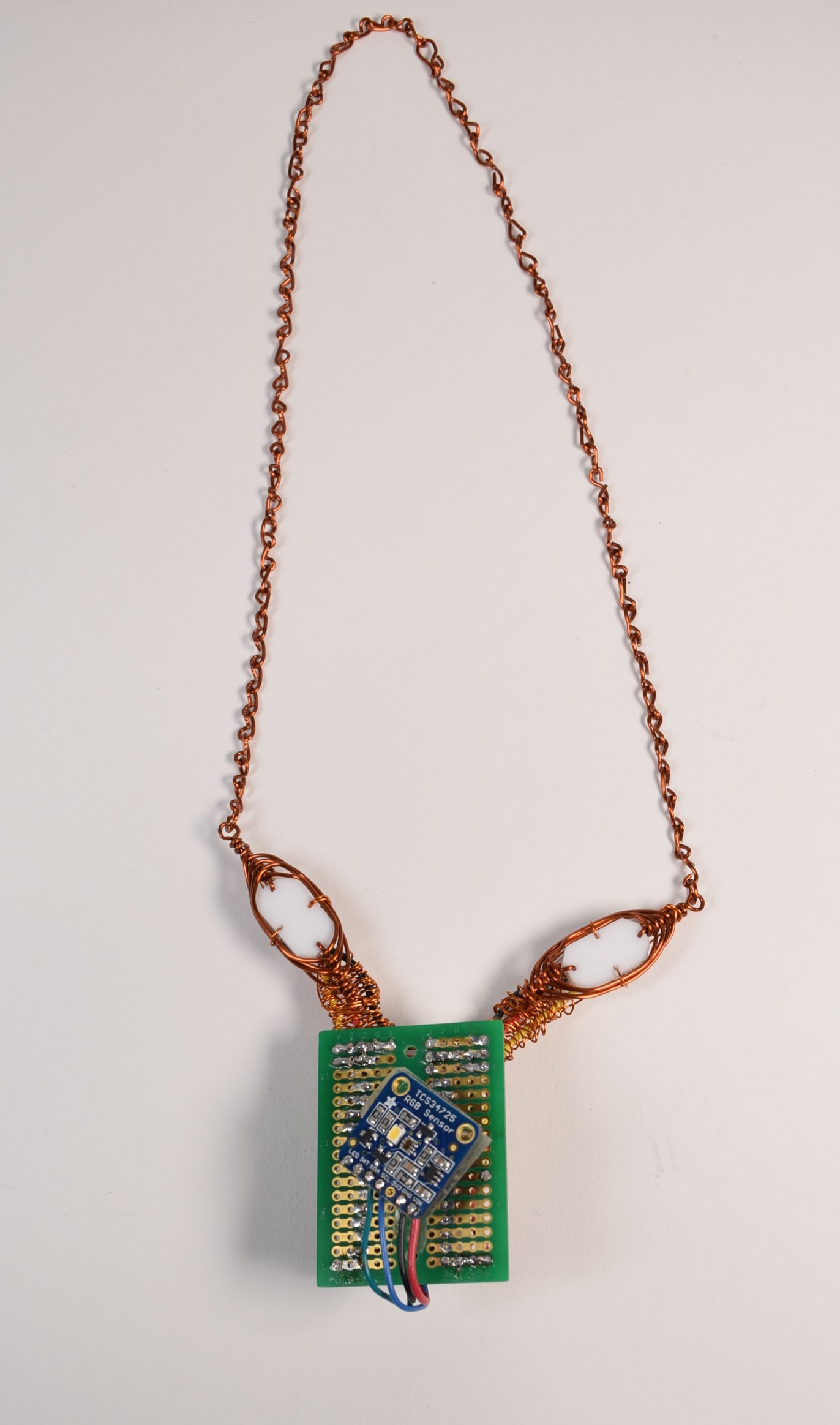
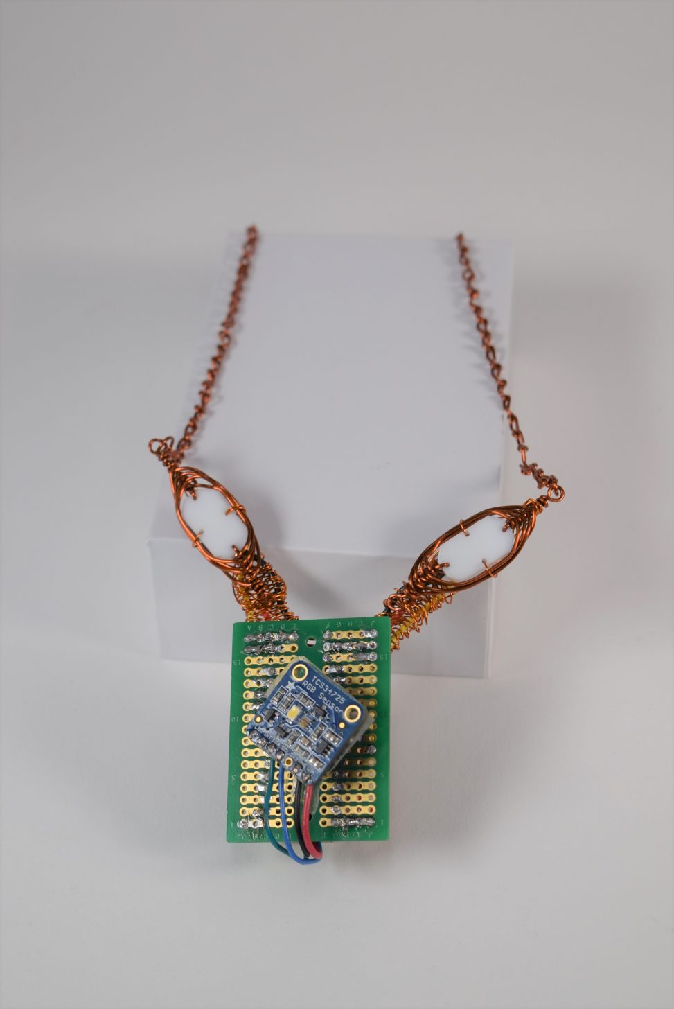
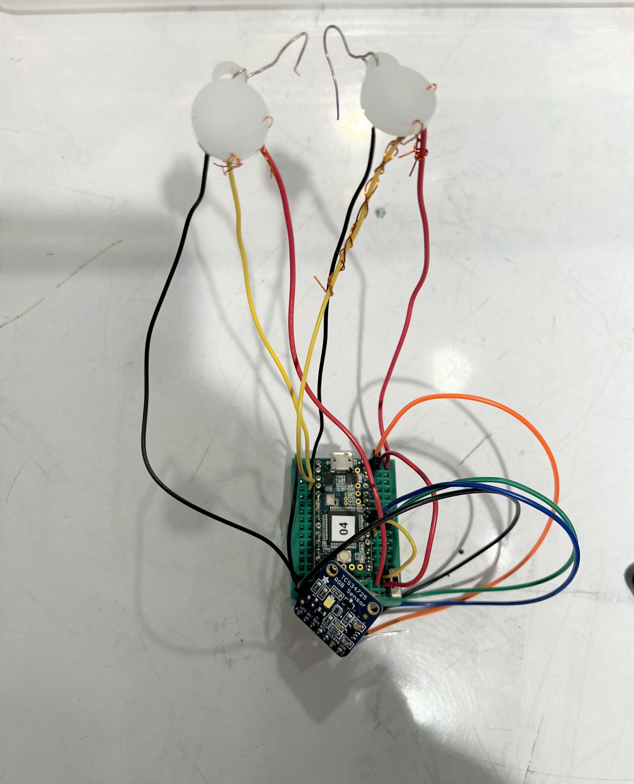
Overall photo of the chameleon necklace.
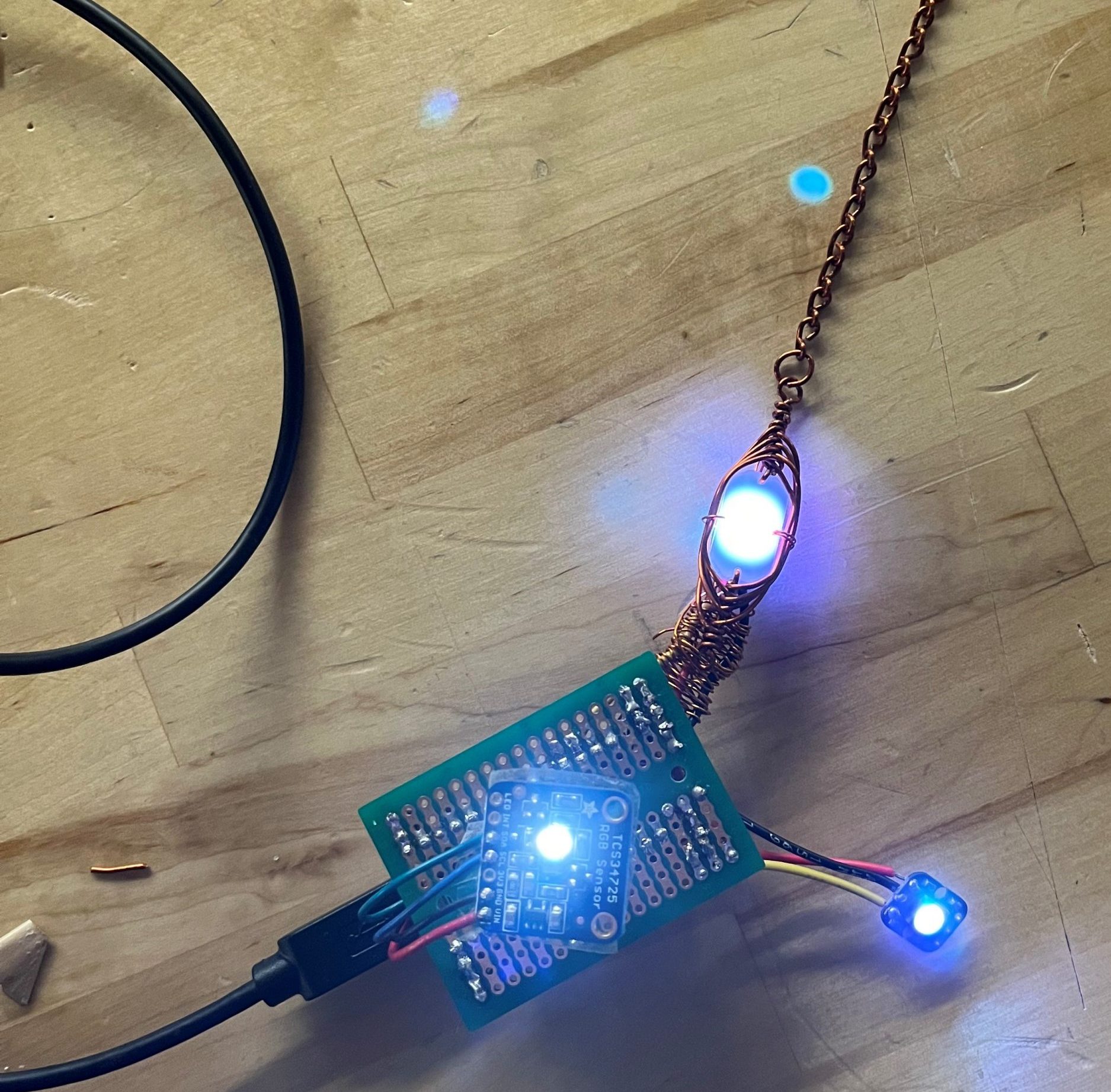
Detail Photos:
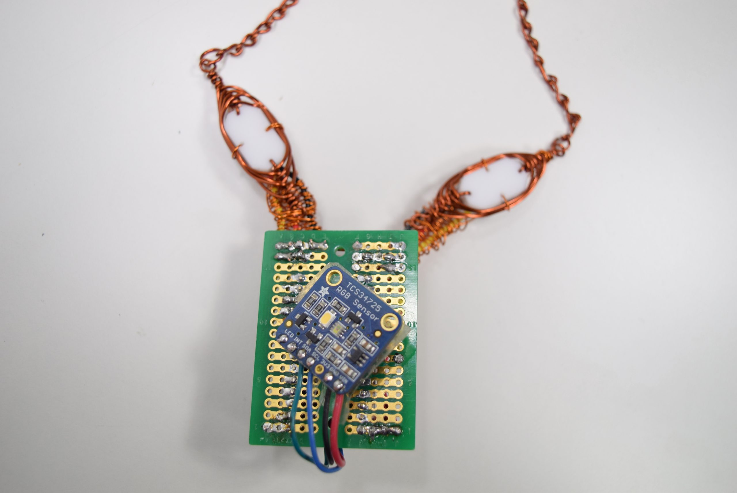
TCS34725 RGB sensor at the center of the necklace reads the color of surrounding objects.
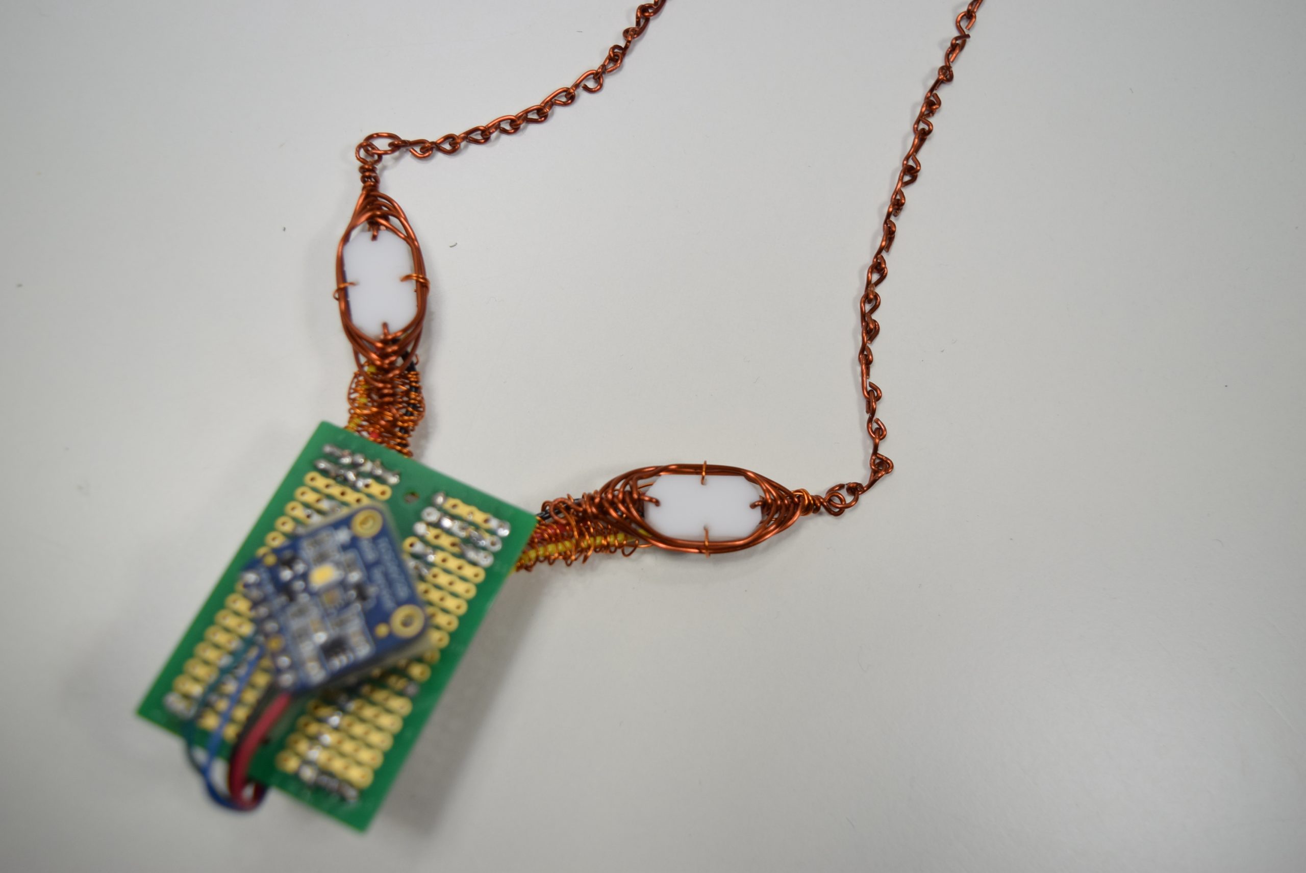
Wire-wrapped acrylic beads are placed on top of the color-changing RGB LEDs.
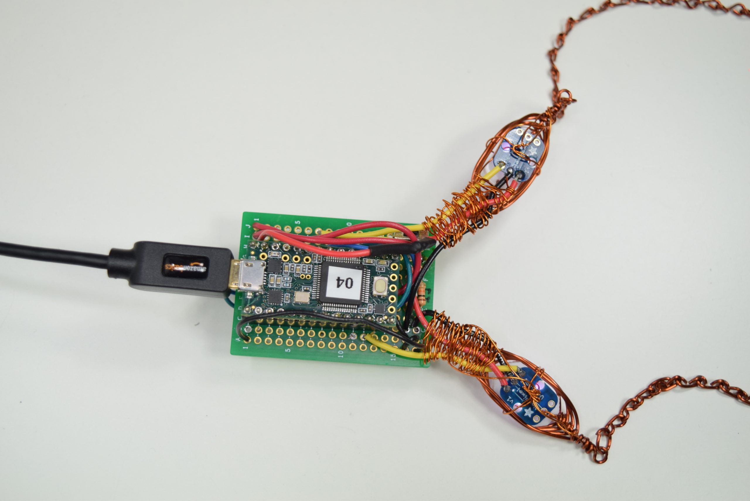
The backside of the necklace pendant includes the Teensy3.2 microcontroller, a slide switch, and both RGB LEDs that illuminate the acrylic beads.
Necklace in Use:
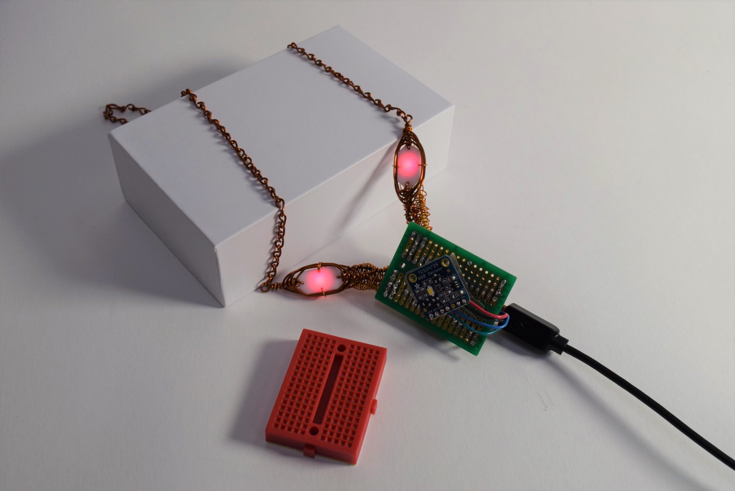
The necklace displaying the color of the red breadboard.
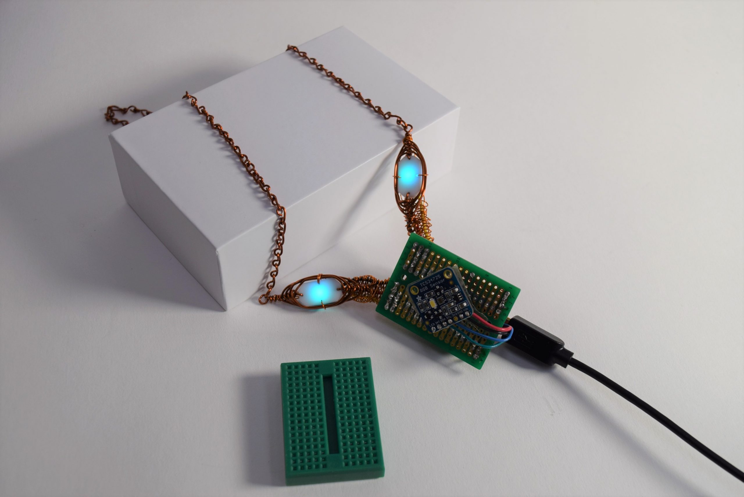
The necklace displaying the color of the green breadboard.
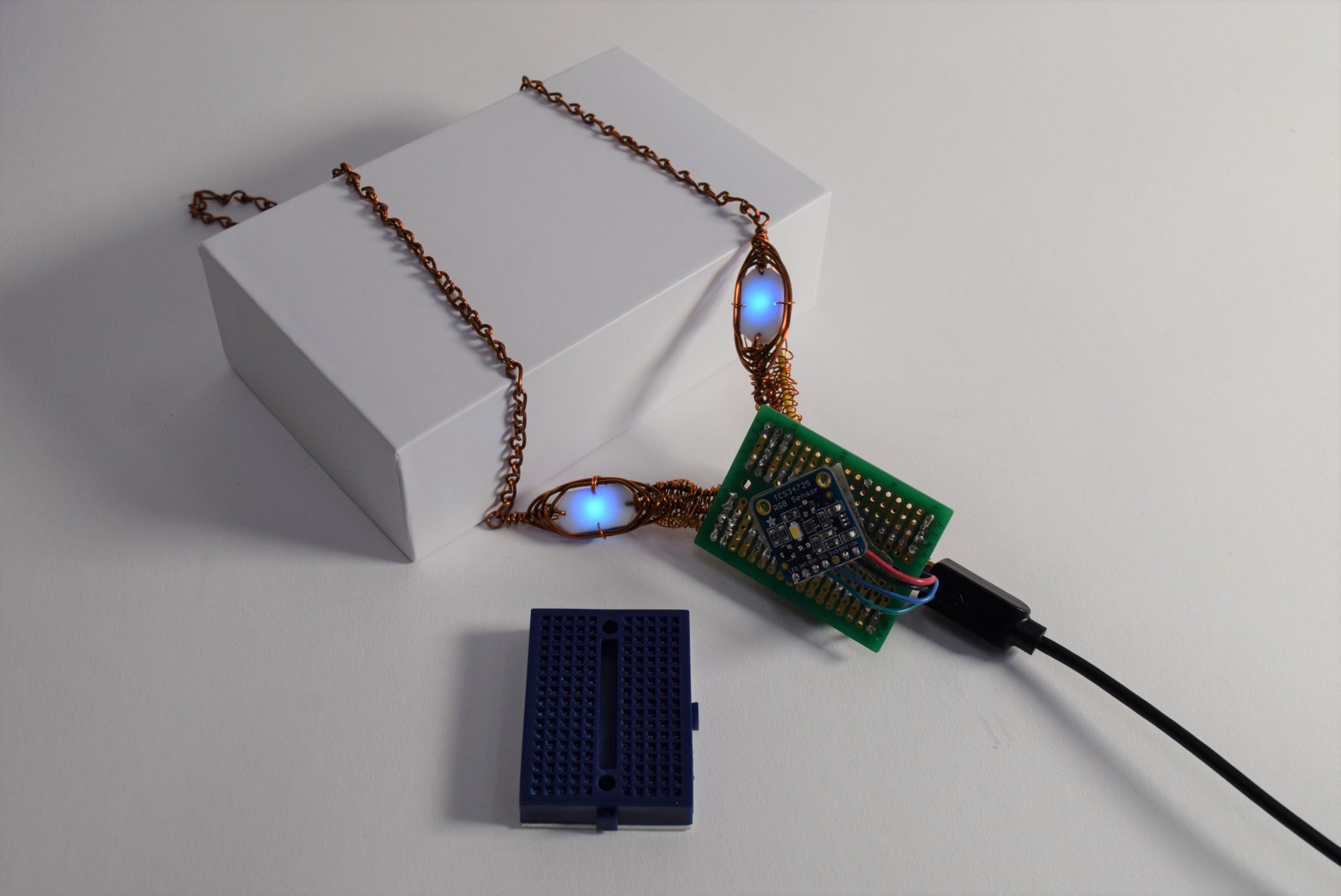
The necklace displaying the color of the blue breadboard.
Video:
The necklace changes color to match the breadboards held in front of the RGB sensor. The switch on the backside of the protoboard is flipped to keep a given color displayed on the necklace beads.
Process:
Decision 1:
The first big decision of this project was to use the Teensy3.2 microcontroller over the Attiny85. Although the small size of the Attiny85 made it ideal for jewelry, it wasn’t compatible with the tcs34725 RGB color sensor library. By switching to Teensy3.2, my necklace was a bit bulkier, but this microcontroller was much easier to code with and compatible with all the libraries I needed for my project.
Decision 2:
The second big decision I made was to change my project concept from chameleon earrings to a chameleon necklace. I realized that the dangling wires connecting the RGB sensor on a hidden wristband/necklace to a pair of earrings might be uncomfortable for the user. It felt more practical to contain all of the hardware on a single necklace.
Chameleon Earrings “works-like” prototype
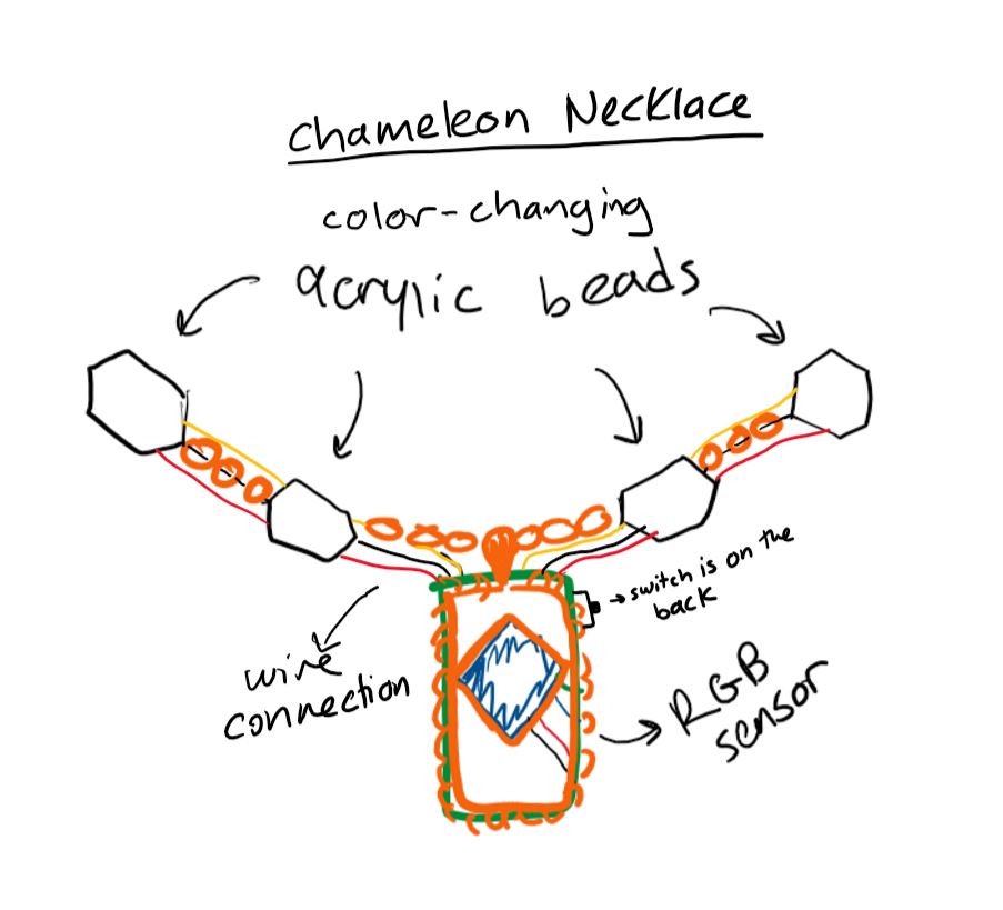
I changed my project to a chameleon necklace based on this sketch after the prototype presentations.
Process Images:
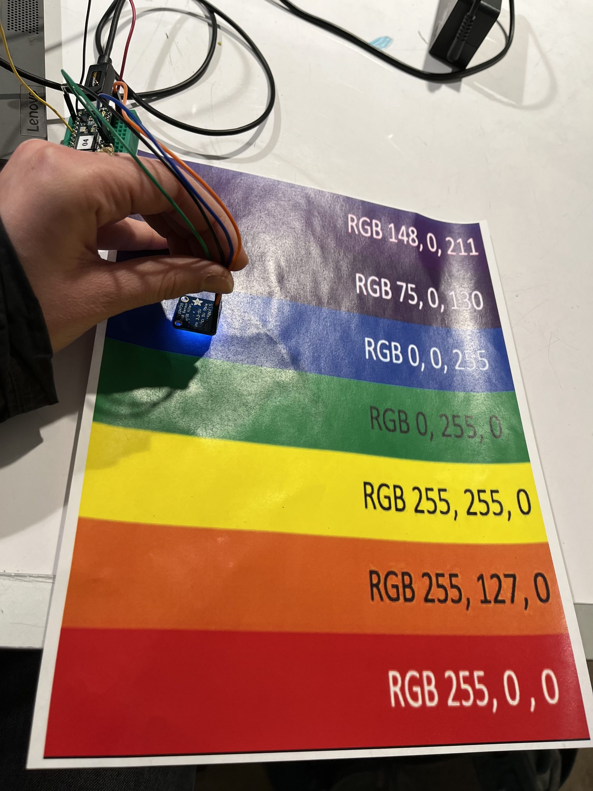
Comparing the tcs34275 RGB sensor readings of various colors to their actual RGB values.
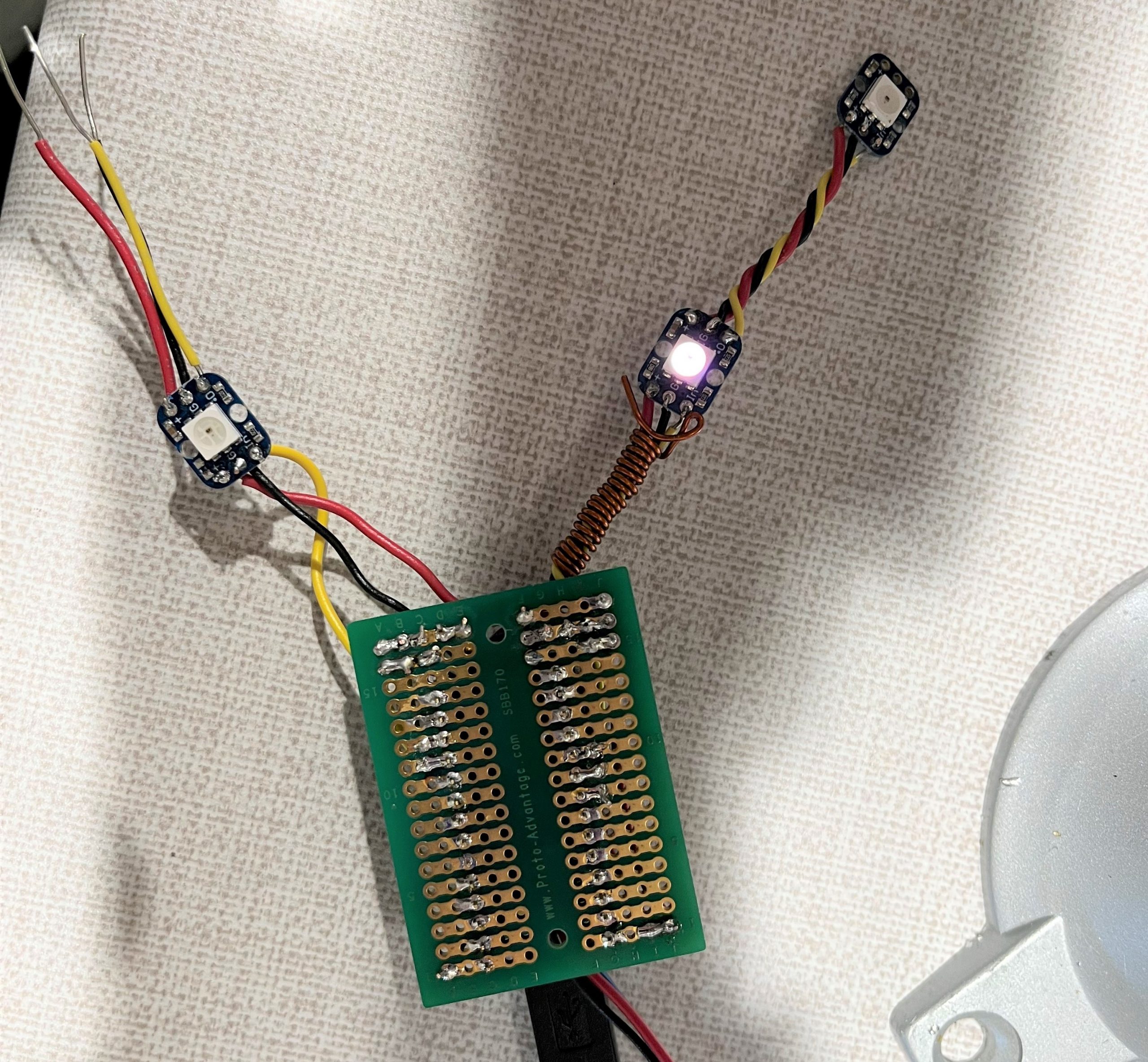
While soldering the electronic circuit for the necklace, the left side of the necklace was not lighting up. I had to re-solder the wires connecting the output pins to the LEDs on the left side after I realized they were loose.
For the final step of my project, I created a herringbone wire wrap for the acrylic beads and a wire chain. I learned both techniques from YouTube tutorials.
Discussion:
My original goal for this project was to create a pair of “chameleon” earrings with LEDs that would light up in the same color as an object placed in front of an RGB sensor. I created a “works-like” prototype of the earrings for the prototype presentation. A common concern in the feedback I got from the class was that the earrings would have a lot of dangling wires, which might make them hard to wear and very fragile. One classmate suggested that I “try wireless if want to use for earring.” While I originally wanted to have a wireless Bluetooth connection between the earrings and microcontroller/RGB sensor set-up, Zach warned me that the Bluetooth chips we had were probably too big to be used for earrings. I got another comment that “if it is hanging on your neck, maybe you could even turn that into a necklace.” I was initially hesitant to go down this route since I wanted to hide the electronics and feature the color-changing LEDs in the jewelry. However, after doing more sketches of a revised design, I realized that the protoboard and RGB sensor could also look nice as part of the necklace. Moving forward, I changed my project to be solely a necklace instead of earrings with the electronics on a hidden necklace or wristband.
While working on the chameleon necklace, I experienced the difficulties of creating smaller-scale electronic devices, especially wearables. I wanted to use the smallest possible microcontroller and fit all the electronics onto the smallest possible protoboard to reduce the bulk of the necklace pendant. I started with the Attiny85 and spent almost a week searching for ways to make the Tcs34725 RGB sensor library compatible with this microcontroller. After running into many dead ends, I switched to the Teensy3.2 microcontroller. In hindsight, I wish I didn’t get so hung up on using the Attiny85. If I had moved on to Teensy3.2 earlier, I would have had more time to assemble my necklace at the end, which was another challenging part of this project. While constructing the final necklace, I had to extensively plan how to fit all of the wires, resistors, sensors, and actuators on the small protoboard. Although it was frustrating to resolder the many loose/broken wire connections I found, this process helped me strengthen my soldering skills.
Overall, I feel like I achieved most of my goals for this project. My necklace can display most rainbow colors and has an eye-catching design. I still think my soldering could be improved as the final necklace still felt fragile, leading to a broken wire on the final critique day.
In the future, I would try to recreate this necklace using the more flexible stranded wires rather than the solid wires, which are prone to breaking. Also, I would like to have four LEDs on the necklace to draw more attention to the color-changing beads rather than the RGB sensor/microcontroller component.
Block Diagram:

Electrical Schematic:

Code:
/* 60-223 Chameleon Necklace
    Lynn Rushkin

    Description: This code takes the RGB reading from the TCS34275 RGB sensor and sends this RGB value
                 to two RGB LEDs to output light of that color. When the slide switch is in the "on"
                 position, the TCS34275 sensor will take new color readings. When the switch is "off",
                 the sensor will stop taking color readings and the RGB LEDs will continue to display
                 the last color reading the sensor took.

    Pin mapping:
    Arduino pin | type   | description
    ------------|--------|-------------
    10            output    RGB LED pin for color output
    17            input     slide switch pin that reads on/off position of the switch
    20            output    RGB LED pin for color output

    The following sources were consulted to create this code:
    https://courses.ideate.cmu.edu/60-223/s2022/tutorials/button-and-switch
    https://learn.adafruit.com/adafruit-color-sensors/library-reference
    Example code "simple" from the Adafruit_NeoPixel library
    Example code "tcs34725" from the Adafruit_TCS34725 library
*/
//libraries used
#include <Wire.h>
#include "Adafruit_TCS34725.h"
#include <Adafruit_NeoPixel.h>

//pin names
#define PIN1        20
#define PIN2        10
const int switchPin = 17;

//other variables
float red, green, blue;

//defs for RBG LED
#ifdef __AVR__
#include <avr/power.h> // Required for 16 MHz Adafruit Trinket
#endif

// I used a common Anode RGB LED
#define commonAnode true

//define number of RGB LEDs per strand
#define NUMPIXELS 1 // LED strand length of 1 (both RGB LEDs I used were connected to their own output pins)

//name the LED strips "pixels1" and "pixels2" , both containing only 1 RGB LED at PIN1 and PIN2, respectively.
Adafruit_NeoPixel pixels1(NUMPIXELS, PIN1, NEO_GRB + NEO_KHZ800);
Adafruit_NeoPixel pixels2(NUMPIXELS, PIN2, NEO_GRB + NEO_KHZ800);

//define RGB LEDs brightness:
#define BRIGHTNESS 50

// Time (in milliseconds) to pause between pixels
#define DELAYVAL 250

// our RGB -> eye-recognized gamma color
byte gammatable[256];
Adafruit_TCS34725 tcs = Adafruit_TCS34725(TCS34725_INTEGRATIONTIME_50MS, TCS34725_GAIN_4X);


void setup() {
  pinMode(switchPin, INPUT);
  tcs.begin();
  if (tcs.begin()) {
    Serial.println("Found sensor");
  } else {
    Serial.println("No TCS34725 found ... check your connections");
    while (1); // halt!
  }

  // Thanks PhilB for the following gamma table.
  // It helps convert RGB colors to what humans see
  for (int i = 0; i < 256; i++) {
    float x = i;
    x /= 255;
    x = pow(x, .5);
    x *= 255;

    if (commonAnode) {
      gammatable[i] = 255 - x;
    }
    else {
      gammatable[i] = x;
    }
  }
  pixels1.begin(); // INITIALIZE NeoPixel strip object
  pixels1.setBrightness(BRIGHTNESS);

  pixels2.begin(); // INITIALIZE NeoPixel strip object
  pixels2.setBrightness(BRIGHTNESS);
}


void loop() {
  int switchVal = digitalRead(switchPin);

  //The following if-statement ensures that new RGB readings are taken from
  //the sensor only when the switch is on.
  if (switchVal == 1) {
    tcs.setInterrupt(false);  // turn on LED

    delay(60);  // takes 50ms to read

    tcs.getRGB(&red, &green, &blue);

    tcs.setInterrupt(true);  // turn off LED
  }
  else {
    tcs.setInterrupt(true);
  }

  //print the following lines of code to check the RGB sensor readings
  Serial.print("R:\t"); Serial.print(int(red));
  Serial.print("\tG:\t"); Serial.print(int(green));
  Serial.print("\tB:\t"); Serial.print(int(blue));

  Serial.print("\n");

  /*After collecting RGB readings from the tcs34275 sensor with all the rainbow colors,
    I found that the readings never dropped below 20 or got higher than 200.
    To acheive a closer color match in the LED output to the object color input, I mapped the
    sensor readings from the range of 20 - 200 to the range 0 - 255 for modified color values.
    */
  int redMod = map(int(red), 20, 200, 0, 255);
  int greenMod = map(int(green), 20, 200, 0, 255);
  int blueMod = map(int(blue), 20, 200, 0, 255);

  // Send the updated pixel colors to the RGB LEDs.
  pixels1.setPixelColor( 0, pixels1.Color(int(redMod), int(greenMod), int(blueMod)) );
  pixels2.setPixelColor( 0, pixels2.Color(int(redMod), int(greenMod), int(blueMod)) );

  pixels1.show();
  pixels2.show();


  delay(DELAYVAL); // Pause before next pass through loop
}