Tingsong’s Double Transducer
Cassie’s double transducer
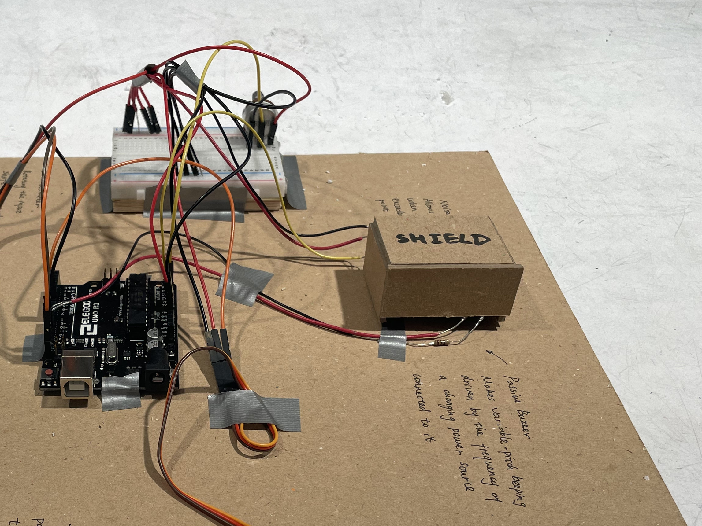
A shield to isolate the buzzer and sound detector from environmental noises
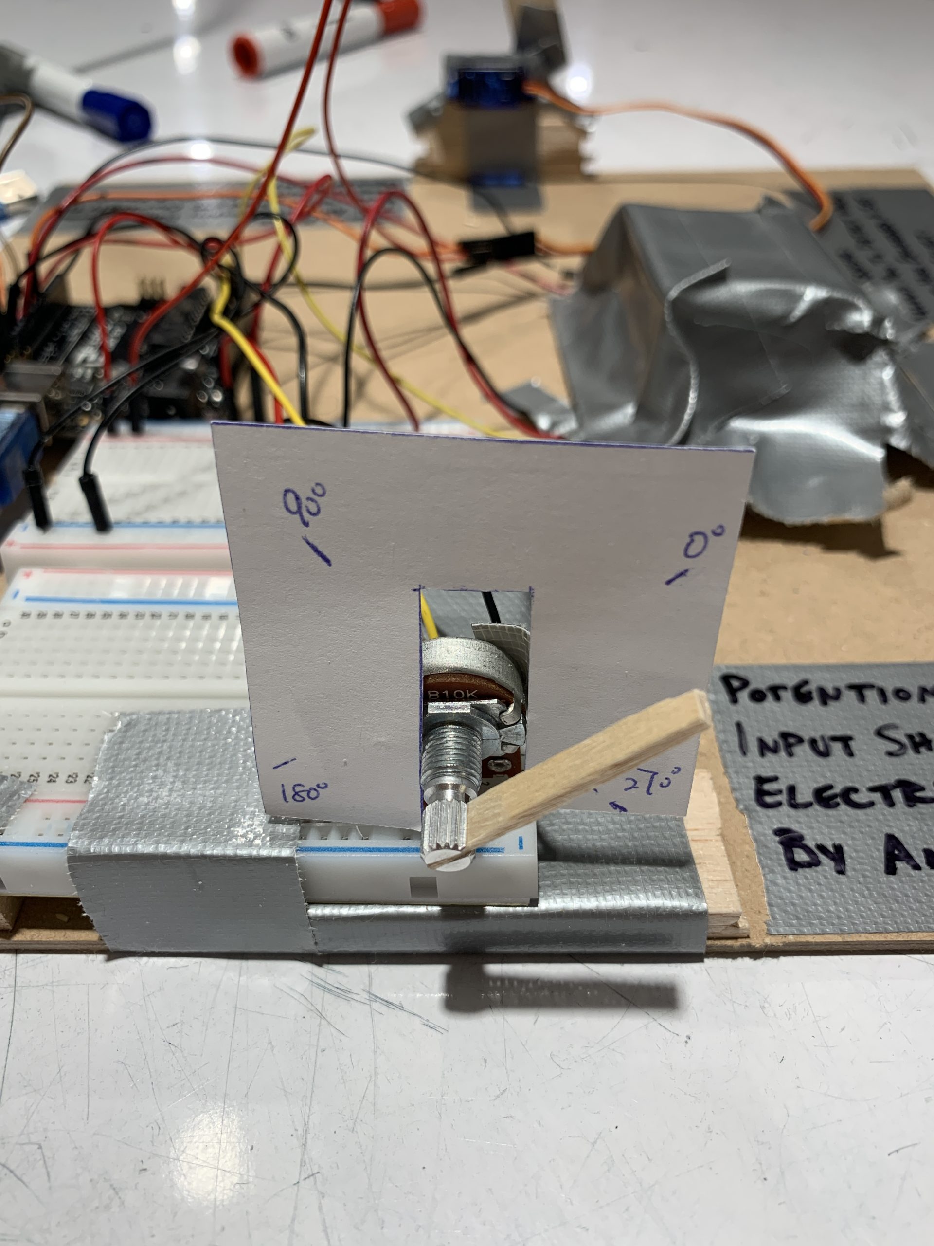
Scale to measure what angle the potentiometer is rotated to
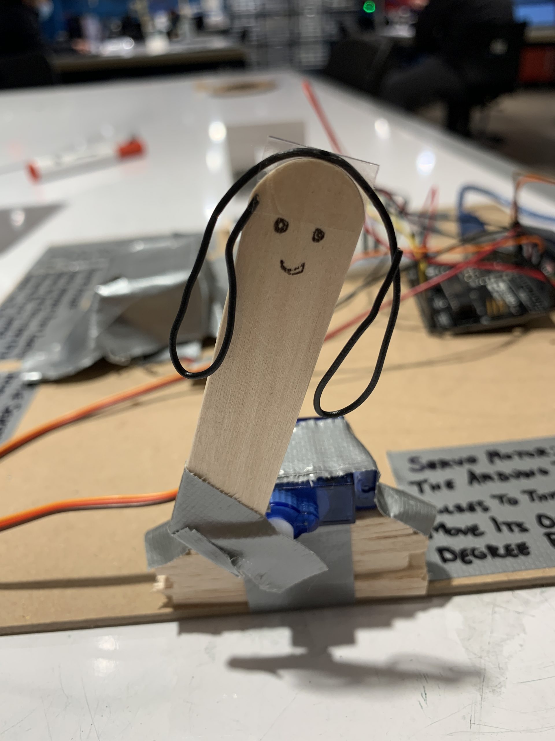
Cute person attached to the servo
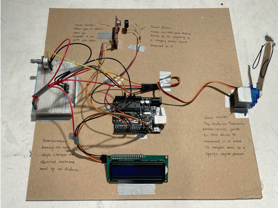
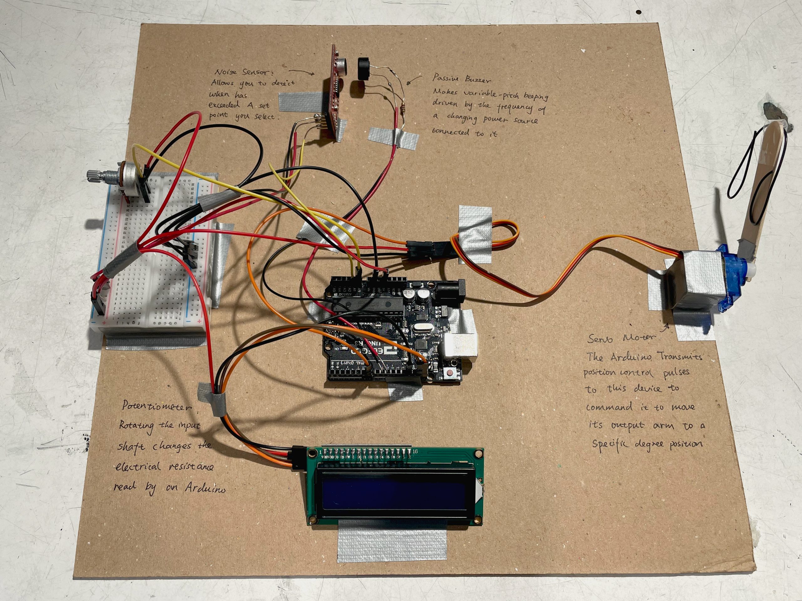
Narrative Description
When the potentiometer is turned it tells the buzzer to make sound and then the noise sensor listens to this sound and tells the servo to move its arm up and down once per second. When the potentiometer is turned more, the buzzer makes more noise and the servo moves its arm up and down twice per second. When the potentiometer is turned even more, the buzzer makes more noise and the servo moves its arm up and down three times per second. The Arduino lets the different pieces talk to each other and lets us change what they are saying to each other using coding.
Process Pictures
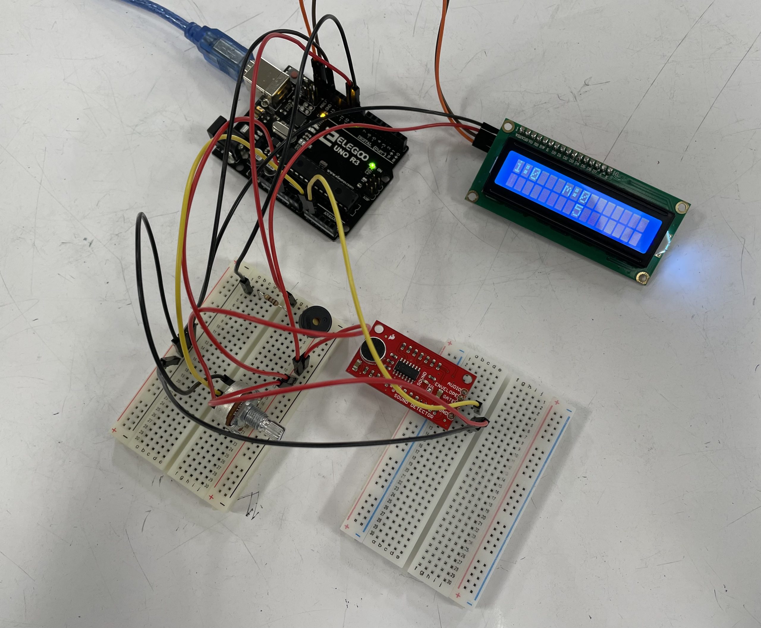
Testing buzzer’s frequency and volume range to ensure the sound detector sensitive enough to detect the volume change
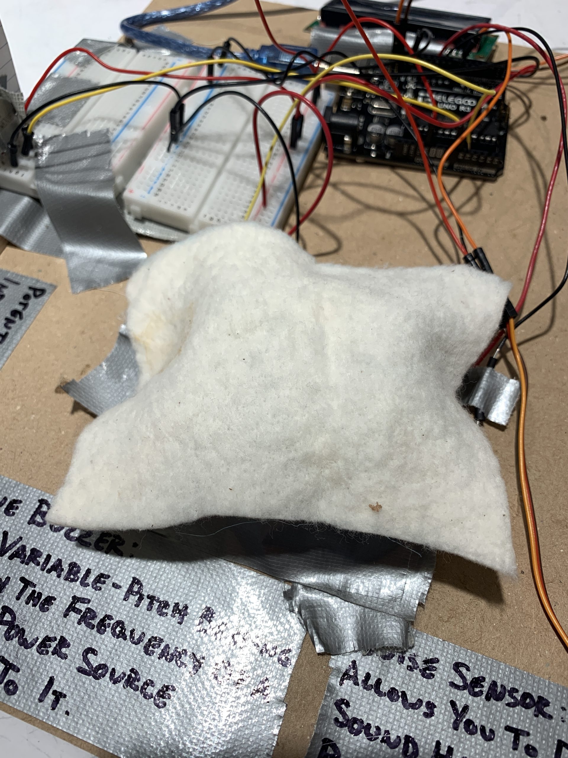
Testing different materials and how well they muffle sound
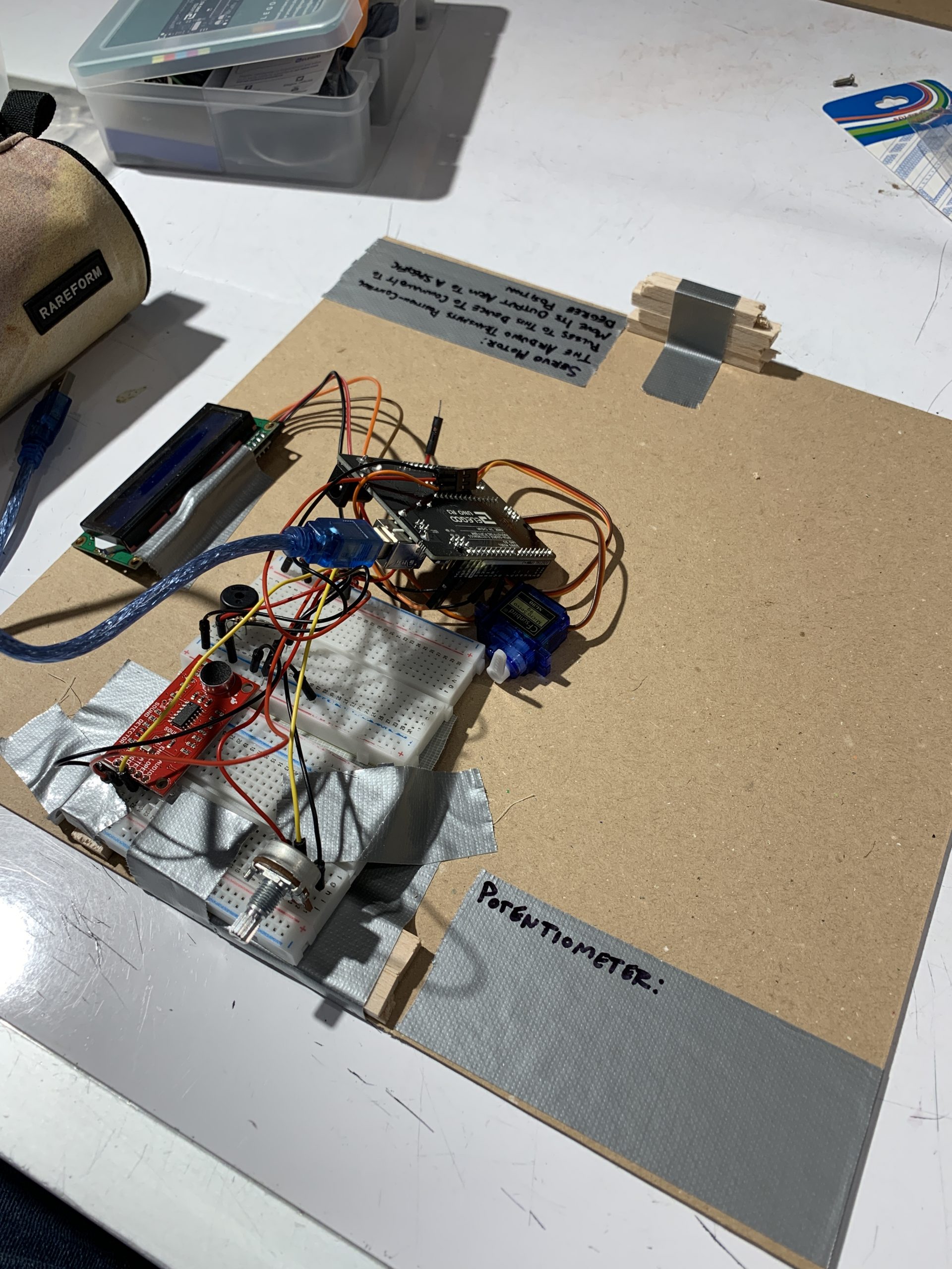
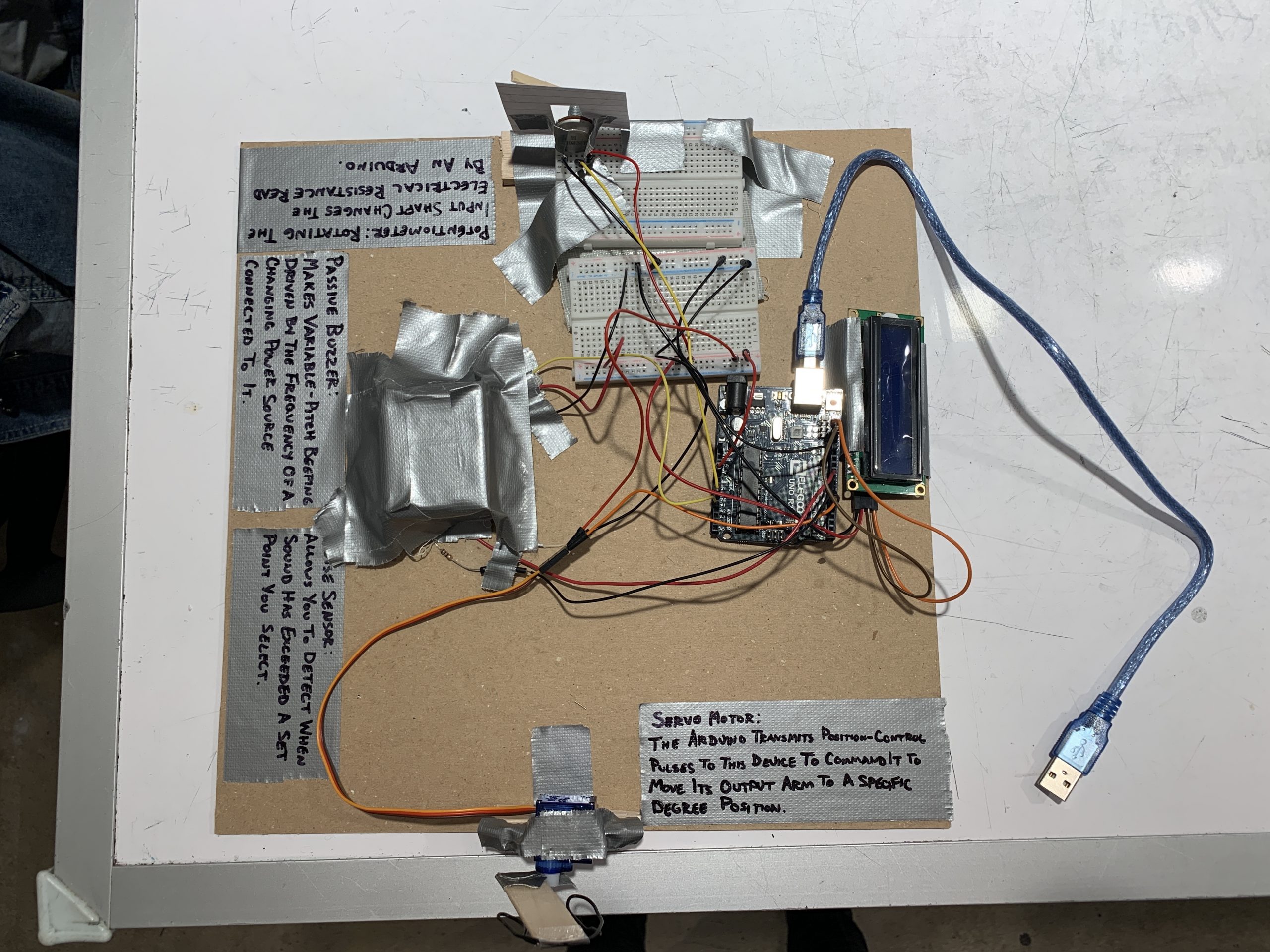
Process of labeling and organizing board
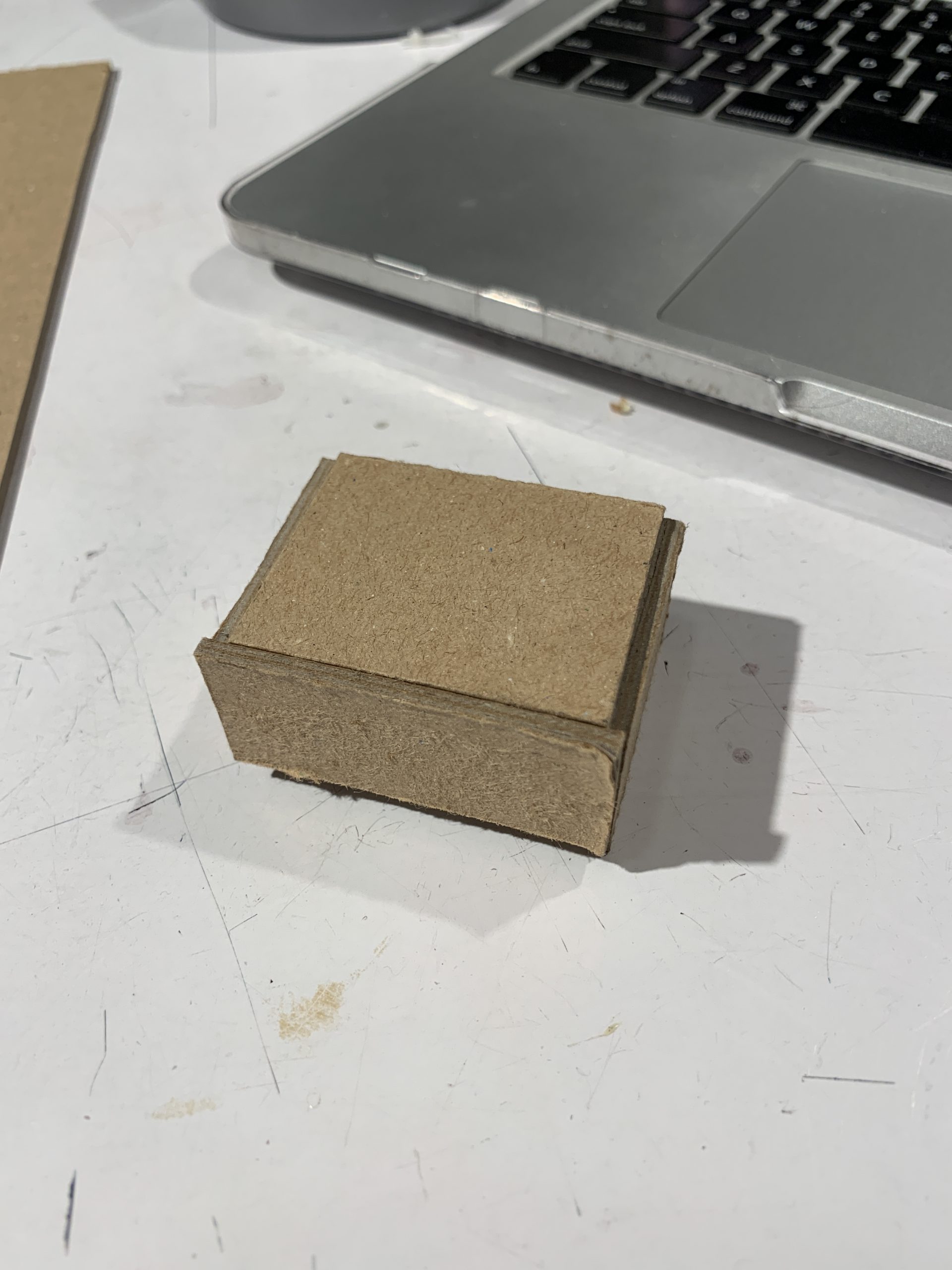
Sound shield just after being constructed
Discussion
This project, while seemingly simple, was very difficult to make work. Conceptually both of us understood what it took to make this double transducer, but there were a lot of small issues that had to be overcome.
At the beginning of this project, Tingsong had suggested using a solenoid to create our tapping action, and looking back we wish that we had at least tried this method instead of going right to a servo. While a servo might be conceptually simpler, we ran into a lot of issues towards the end of our project with our servos. The largest was tackling the issue of not being able to use both the servo library and the buzzer library when coding. We ended up coding directly to the servo without using the library, but there were a lot of small complications that came from this. We also had two servos that acted completely differently despite using the same code.
There were also some issues that came with using the buzzer and the noise sensor. The noise sensor was having a lot of interference from ambient noise sources that threw off our results, especially with picking up noise from our servo instead of only the buzzer. We combated this with a small box to isolate the noise sensor and the buzzer and even experimented with different materials and what would block outside noise most effectively. We overcame this issue, but we spent a while thinking that a separate problem was due to the noise sensor detecting ambient sound, so this ended up confusing us and wasting time.
Despite the issues that we ran into, we both learned a lot from this project. Tingsong taught Cassie about some coding things that she was inexperienced with, and Cassie helped Tingsong solder for the first time. The wiring and mechanical side of this project was surprisingly easy and without issue other than the two servos that behaved differently. We worked very well as a team and stayed upbeat despite the setbacks.
Functional Block Diagram

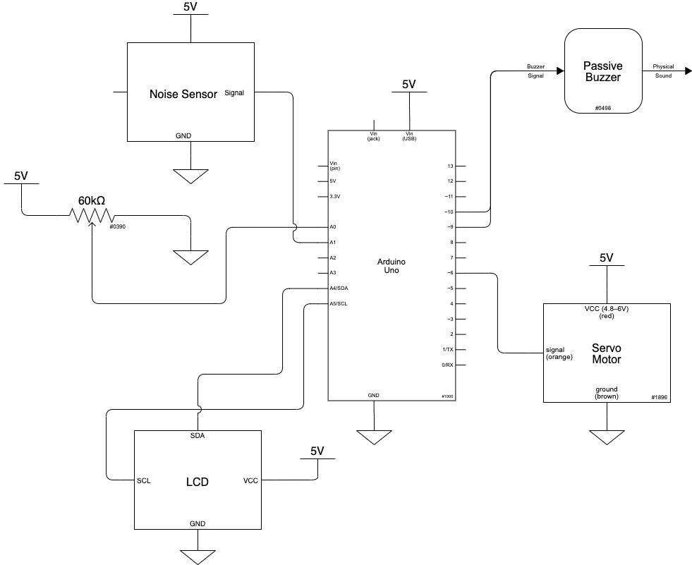
Electrical Schematic
Code
/*Project Title: Double Transducer: Rotational Position to Frequency of Tapping
  Team Members: Casandra Rausch, Tingsong (Terrence) Ou
  Description: Using potentiometer to change the rotational angle, the angle range was limited to 0 to 90 degrees.
               Changing the rotational angle increases/decreases the Buzzer's volumn
               Sound detector detecting the Buzzer's volumn then map it to 0-1023 input read range
               Arduino mapping the value from sound detector to [500, 250, 166], which are delay times for different frequency
               Servo read delay and perform tapping, 500 delay causes 1 tapping per second, 250 causes 2, and 166 causes 3

  Pin mapping:
    Arduino pin | role   | description
    ------------|--------|-------------
    A0            input     Potentiometer
    A1            input     Sparkfun Sound Detector
    6             output    Servo for simulation tapping frequency
    9             defined   Buzzer (one connection)
    10            defined   Buzzer (another connection)
*/

#include <toneAC.h> //Library for buzzed
//Libries for LCD
#include <Wire.h>
#include <LiquidCrystal_I2C.h>

//Creating LCD
LiquidCrystal_I2C screen(0x27, 16, 2);

//Define pins
const int potenPIN = A0,
          sndDetPIN = A1,
          tapperPIN = 6;

//I tested several frequencies and found 1500 is
//responsive to the change of volume
const int defFreq = 1500,
          LCDLow = 0,
          LCDHigh = 99,
          volLow = 0,
          volHigh = 10,
          initTestPeriod = 2000; //Test time in void step() part

int detLow = 1023,  //initialize detected lowest value (as large as possible)
    detHigh = 0;  //initialize detected highest value (as small as possible)

int potenLCD = 0;
int buzzerLCD = 0;
int sndDetLCD = 0;

//creating a timer for LCD
unsigned long lastTime = 0;
unsigned long LCDInterval = 250; //refreahing LCD every 250 milliseconds


void setup() {
  //Initializing LCD
  screen.init();
  screen.home();
  screen.backlight();

  pinMode(potenPIN, INPUT);
  pinMode(sndDetPIN, INPUT);
  pinMode(tapperPIN, OUTPUT);

  Serial.begin(9600);


  /*Buzzer should first play sound in Lowest and Highest volumes
    such that sound detector can generate lower bound and higher bound
    of sound range*/
  int counter = 0;
  while (counter < initTestPeriod) {
    if (counter < initTestPeriod / 2) {
      toneAC(defFreq, volLow);
      delay(1);
      int sndRecVal = analogRead(sndDetPIN);
      if (sndRecVal < detLow) detLow = sndRecVal;
    } else {
      toneAC(defFreq, volHigh); //Offset
      delay(1);
      int sndRecVal = analogRead(sndDetPIN);
      if (sndRecVal > detHigh) detHigh = sndRecVal;
    }
    counter ++;
  }
  detHigh *= 0.75;
  toneAC(defFreq, volLow);
  delay(100);

}


void loop() {
  //reading value from potentiometer, convert to volumn
  int potenVal = analogRead(potenPIN);
  int buzzerVol = map(potenVal, 0, 1023, volLow, volHigh);
  toneAC(defFreq, buzzerVol);

  //detecting volumn
  int sndRecVal = analogRead(sndDetPIN);
  //converting read value to delaytime
    int delayTime = 1000;
    if (sndDetLCD < 30){
      delayTime = 500;
    } else if (sndDetLCD < 70){
      delayTime = 250;
    } else{
      delayTime = 166;
    }

  //Running servo
  runServo(delayTime);

  int servoLCD = 0;
  if (delayTime == 500) servoLCD = 0;
  else if (delayTime == 250) servoLCD = 50;
  else servoLCD = 99;

  //Displaying Values on LCD
  displayOnLCD(potenVal, buzzerVol, sndRecVal, servoLCD);
}


/*
  -----------------------HELPER FUNCTIONS--------------------
*/

void runServo(int delayTime){
  servoWrite(tapperPIN, 30);
  delay(delayTime);
  servoWrite(tapperPIN, 60);
  delay(delayTime);
}


//Maping values to 0-99 range then displaying on LCD
void displayOnLCD(int potenVal, int buzzerVol, int sndRecVal, int servoLCD) {
  if (millis() - lastTime >= LCDInterval) {
    //Map read values to LCD values (0 - 99);
    potenLCD = map(potenVal, 0, 1023, LCDLow, LCDHigh);
    buzzerLCD = map(buzzerVol, volLow, volHigh, LCDLow, LCDHigh);
    sndDetLCD = map(sndRecVal, detLow, detHigh, LCDLow, LCDHigh);
    sndDetLCD = constrain(sndDetLCD, LCDLow, LCDHigh);

    screen.clear();
    screen.home();
    screen.print("i:");
    screen.print(potenLCD);
    screen.setCursor(6, 0);
    screen.print("m:");
    screen.print(buzzerLCD);
    screen.setCursor(8, 1);
    screen.print(sndDetLCD);
    screen.setCursor(12, 1);
    screen.print("o:");
    screen.print(servoLCD);
    lastTime = millis();
  }
}


// Reference: Robert Zacharias (class instructor)//
// function to drive servo motor without need for servo library
// sample use: servoWrite(SERVOPIN, 50);
void servoWrite(int servoPin, byte servoDegree){
  pinMode (servoPin, OUTPUT); // in case it's not already set

  const int INTERPULSEDELAY = 20; // typical delay between servo pulses

  static unsigned long lastPulseTime;

  if (millis() - lastPulseTime > INTERPULSEDELAY){

    // turn degree input to pulse length output
    unsigned int pulseWait = map(servoDegree, 0, 180, 544, 2400);

    // transmit pulse of specified length
    digitalWrite(servoPin, HIGH);
    delayMicroseconds(pulseWait);
    digitalWrite(servoPin, LOW);

    // reset timer
    lastPulseTime = millis();
  }
}