Sid’s Double Transducer

Andy’s Double Transducer
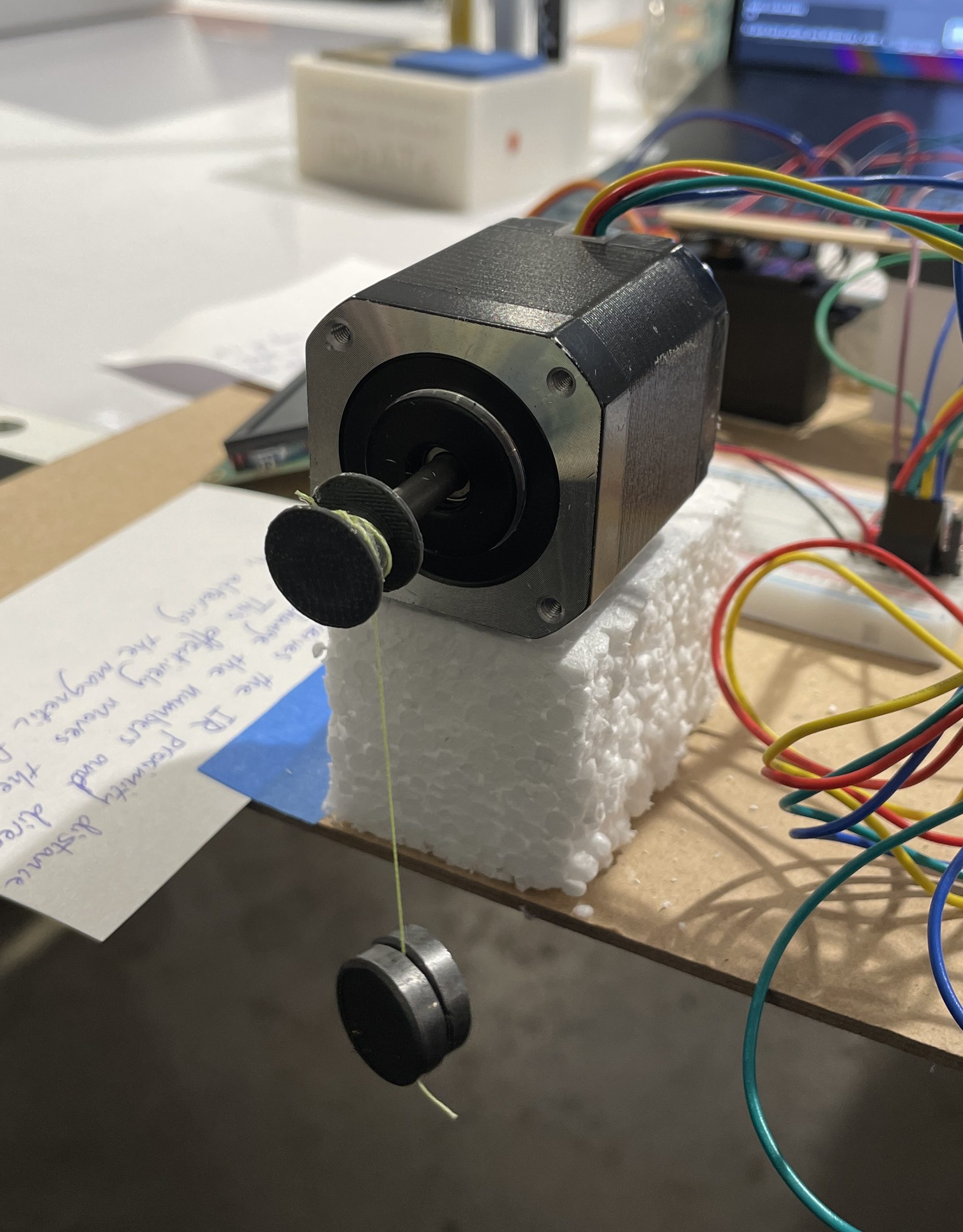
3D printed spindle that reels up a string that is attached to a magnet.
The IR sensor detects the movement in the servo motor and sends a signal to the Arduino.
Narrative Description
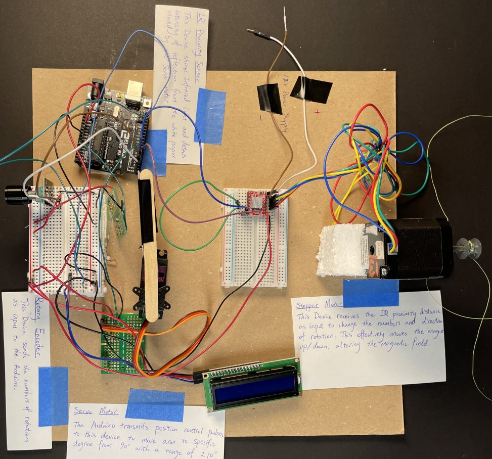
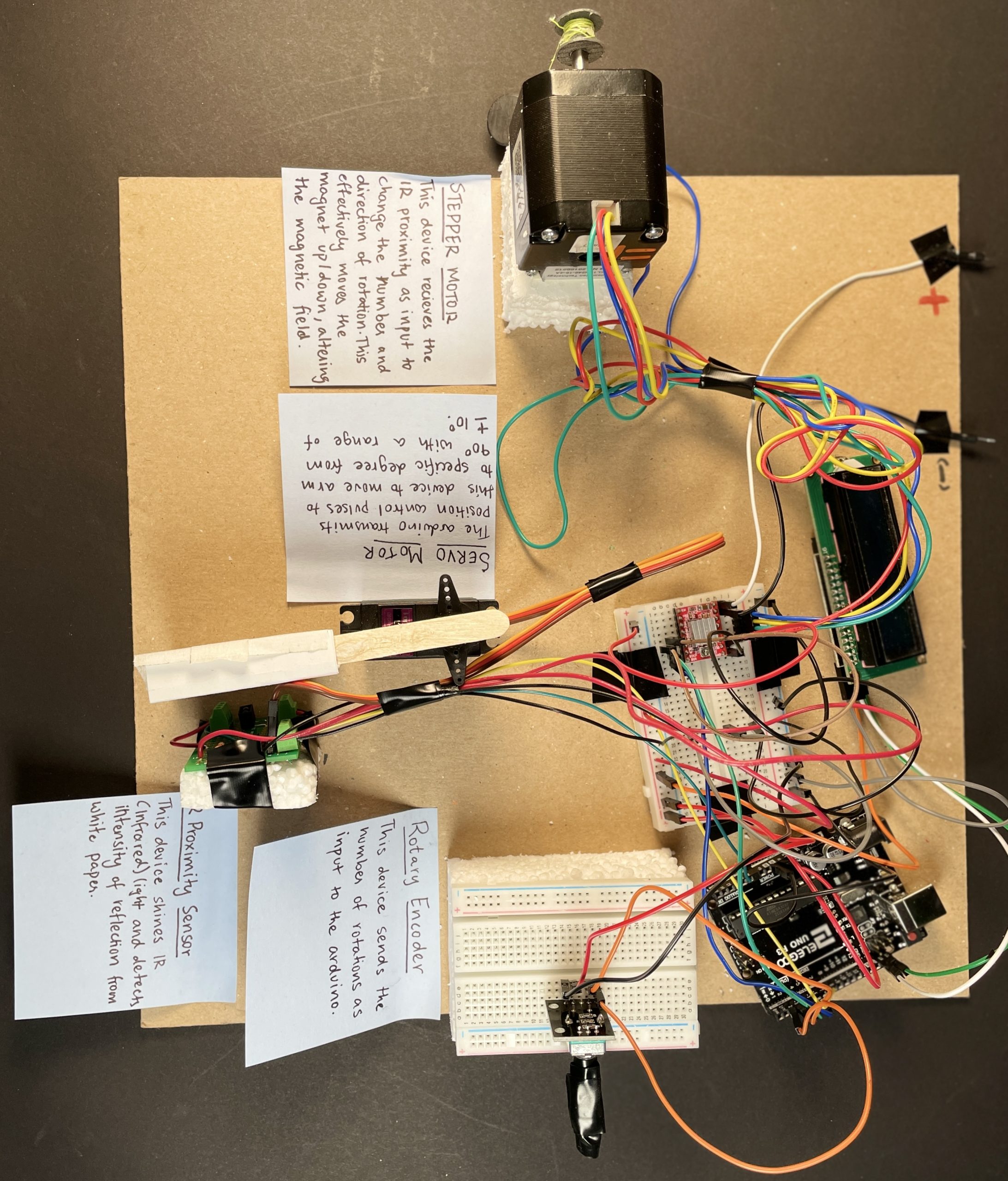
The double transducer receives input in the form of rotational speed and the final output is magnetic field strength. The intermediate output is an angular movement that alters the strength of the magnetic field. We measure rotational speed through a rotary encoder by calculating the number of rotations per second. This is communicated to the Arduino and used to calculate the degree of motion of a servo motor that moves within 20 degrees. The motion is observed by an IR Proximity Sensor which provides the input for a stepper motor to raise and drop a magnet with a string attached to a 3D printed spindle, therefore altering the magnetic field strength.
Discussion
This project has been eye-opening to the world of Arduino and hardware for both of us. The ideation stage was largely based on our individual creativity. Initially, for one of the plans, we thought about incorporating a mounted sensor on wheels to alter the distance as an intermediary step, but given the limited duration and our lack of technical awareness, we switched to a better alternative in the form of the servo motor. We also first thought about using a wire coil to change the magnetic field strength; however, Professor Zacharias informed us of the difficulty in that task and we had to find an alternative. We eventually landed on the idea of using a 3D printed spindle locked into a stepper motor with a string glued onto the spindle to raise and lower a magnetic which worked just as planned in the final demonstration.
It took the combined efforts to create a workable prototype in time for the final deadline. We hit a lot of roadblocks while building the prototype. The unfamiliarity of the potential applications of various hardware slowed us down as we were experimenting with different motors and sensors. However, the guidance we received from professor Zacharias, TA Eric, and the online sources allowed us to meet project deliverables in time.
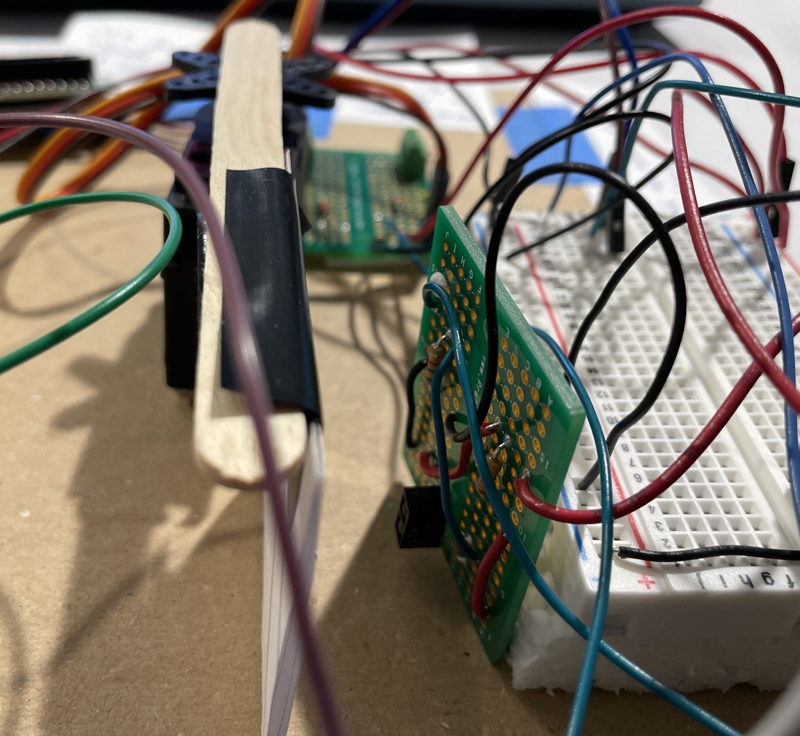
There were a lot of problems we faced when we built out our individual prototypes especially with soldering and the wire connections to the respective sensors/motors. We tried to solder most of the wiring into one protoboard, however, one of the boards ended up short-circuiting the Arduino and sensor due to the lack of scrutiny. It was frustrating as it was a day before the deadline and everything just went horribly wrong. The Arduino did not work in the first run and the IR proximity sensor was short-circuited on the second try. It made us realize the importance of starting early and scheduling the process for managing the workload. Additionally, we understood the significance of proper documentation and schematics and careful inspection before soldering which would have avoided all these problems. Besides the technical implementation, we had issues identifying the right ranges for the input/output from the sensor to the motor. Initially, through trial and error, we used constants and equations to convert the IR proximity input to control the stepper motor. Nevertheless, the professor recommended using the map function in C, to control the stepper which streamlined the code and the implementation efficiently. Now looking back at the project, we could have used a calibration system similar to one that was used by some of our classmates to determine the range after the Arduino just starts up.
Despite all these issues and unfamiliarity, we were able to develop our individual projects by the deadline which worked in tandem with all the other projects on the presentation day.
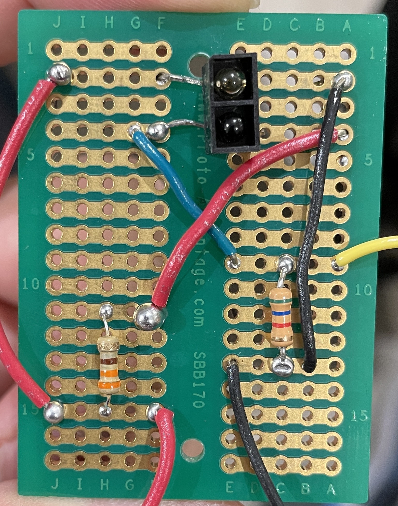
The three red power wires on the left side were misplaced which caused the IR emitter and the Arduino to shortcircuit.
In a rush, I (Andy) misaligned a screw terminal during the soldering process and couldn’t take out the terminal after realizing the mistake.
Picture of the prototype right before Andy short-circuited the IR sensor, Arduino, and the LCD display.
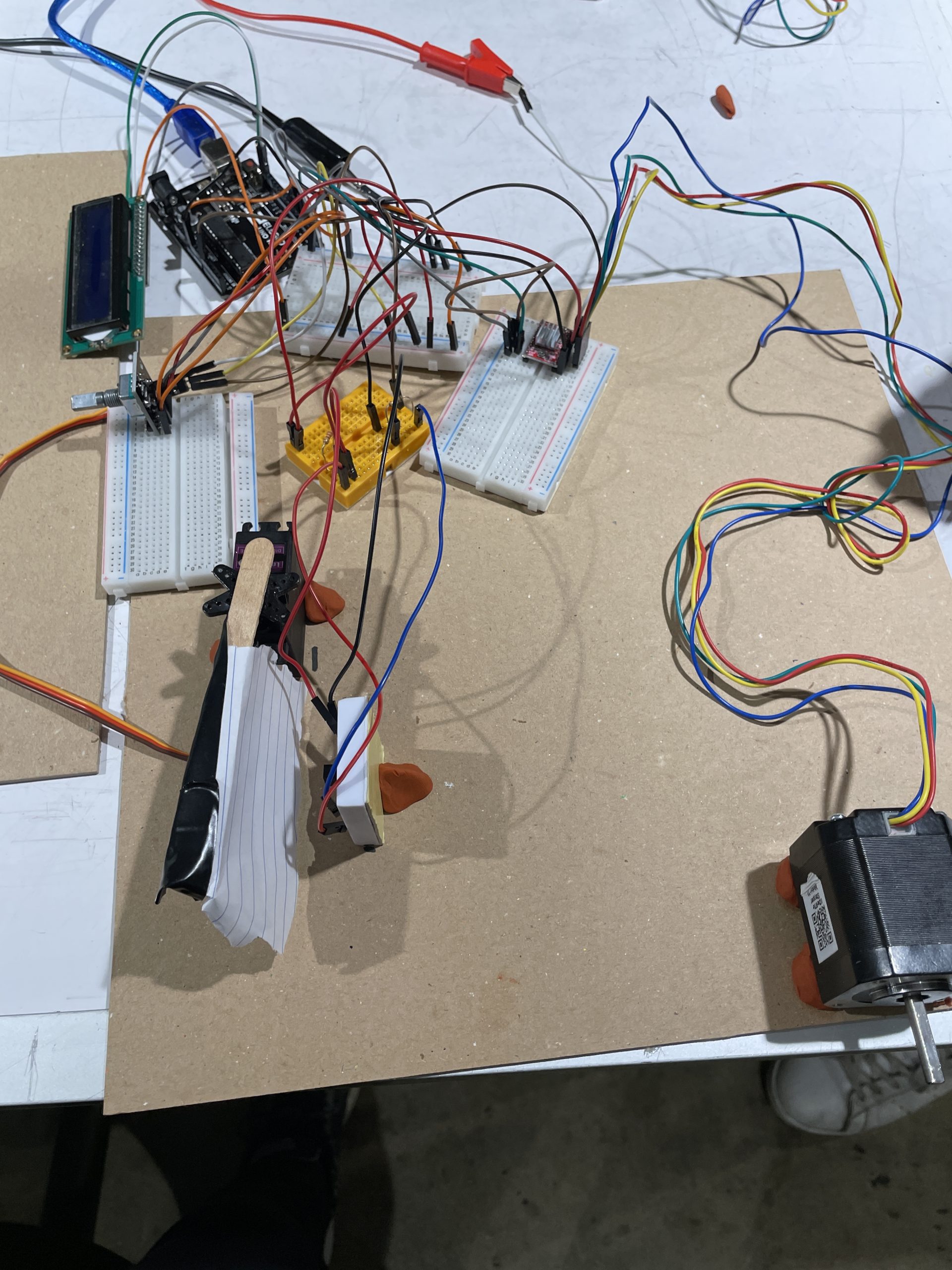
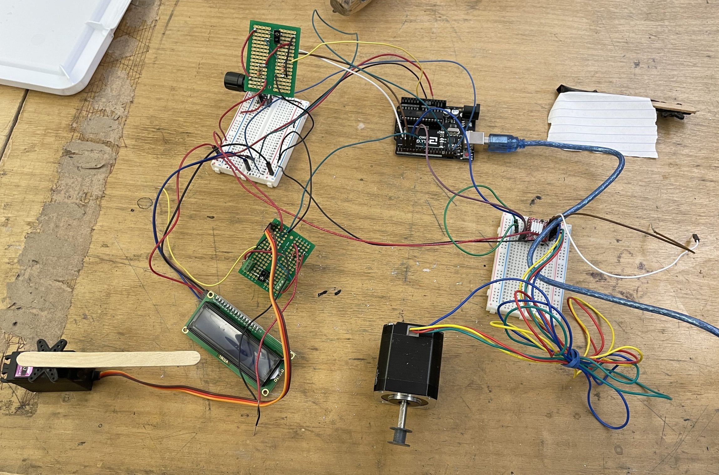
Our first working prototype with all the components together.
Functional Block Diagram

Electrical Schematic

Code
/*Project Title: Double Transducer: Rotational Speed to Magnetic Field Strength
  Team Members: Siddharth Parthiban, Weiwen (Andy) Jiang
  Description: Rotary encoder sends input to arduino to calculate rotational speed.
             Based on input between the ranges of 20 and 60 rotations per second, the servo motor
             is shifted to ± 10 degrees from 90 degrees.
             IR proximity sensor reads the change in motion and sends output to arduino.
             The input from IR proximity sensor is mapped to the input for the stepper motor.
             The stepper motor changes the height of the magnet based on the input.
  Pin mapping:
    Arduino pin | role   | description
    ------------|--------|-------------
    A0            input     IR proximity sensor
    2             input     rotary encoder pin A
    3             input     rotary encoder pin B
    4             output    Stepper Motor
    5             output    Stepper Motor
    8             output    Servo motor
    SCL                     SCL of LCD
    SDA                     SDA of LCD
  Rotoray Encoder Code adapted from https://dronebotworkshop.com/rotary-encoders-arduino/#Arduino_Motor_Encoder_Sketch DroneBot Workshop 2019
*/

#include <Servo.h>
#include <Encoder.h>
# include <AccelStepper.h>
#include <Wire.h>
#include <LiquidCrystal_I2C.h>

//Initialising time and position variables
unsigned long prevTime = 0;
unsigned long prevMotorTime = 0;
unsigned long prevServoTime = 0;
unsigned long oldTimeDisplay = 0;
unsigned long prevIRTime;

//Initialising other variables
long oldPosition  = 0;
float rotatSpeed;
float rotations;
float prevRotation = 0;
int pos = 800;
int prevIRVal = 0;
int servoDegree = 90;
int newDistance = 0, oldDistance = 0;
int changeCheckNew = 0, changeCheckOld = 0;
int irVal = 0;


//Initialising pin ports for Arduino
const int DOORMOTORPIN = 8;
const int STEP_PIN = 4;
const int DIR_PIN = 5;
const int INFRAREDPIN = A0;

//Constant for Rotary Encoder to Servo motor
const int encodToDegree = 20 / 1800;

//Making servo and stepper objects
AccelStepper myMotor(1, STEP_PIN, DIR_PIN);
Encoder myEnc(2, 3);
Servo doorMotor;
int motorPOS;
int MotorCur;


LiquidCrystal_I2C screen(0x27, 16, 2); //Declaring LCD screen object

void setup() {
  Serial.begin(9600); //setting data rate
  doorMotor.attach(DOORMOTORPIN); //declaring pin for servo motor

  //Setting up servo motor
  doorMotor.write(servoDegree);
  pinMode(INFRAREDPIN, INPUT);

  //Setting up Stepper motor
  myMotor.setMaxSpeed(1000);
  myMotor.setAcceleration(500);

  //Setting up LCD screen
  screen.init();
  screen.backlight();
  screen.home();
}

void loop() {
  rotations = myEnc.read(); //read rotary encoder input

  //Calculate rotational speed for every second
  if ((millis() - prevTime ) >= 1000) {
    prevTime = millis();
    rotatSpeed = ((rotations - prevRotation) / 80) * 60;
    prevRotation = rotations;
  }

  //Move servo motor based on rotational speed for every second
  if (( millis() - prevServoTime) >= 1000){
    prevServoTime = millis();
    if ((0 <= abs(rotatSpeed)) && (abs(rotatSpeed) <= 60)) {
      if (rotatSpeed > 0) {
        servoDegree = 90 + ((rotatSpeed) * 0.1667);
        doorMotor.write(servoDegree);
      } else {
        servoDegree = 90 - ((rotatSpeed) * 0.1667);
        doorMotor.write(servoDegree);
      }
    }
  }

  //Read IR proximity sensor input for every 1/2 second
  if ((millis() - prevIRTime) >= 500) {
    prevIRTime = millis();
    irVal = analogRead(INFRAREDPIN);
  }

  //Move Stepper motor based on input from IR proximity sensor every second
  if ((millis() - prevMotorTime ) >= 1000) {
    prevMotorTime = millis();
    motorPOS = map(irVal, 200, 350, 0, 5000);
    myMotor.moveTo(motorPOS);
    myMotor.run();
    MotorCur = myMotor.currentPosition() / 200;
  }
  myMotor.run(); // run Stepper motor

  //Display values to LCD screen
  if (millis() - oldTimeDisplay >= 250) {
    oldTimeDisplay = millis();
    screen.clear();
    screen.setCursor(0, 0);
    screen.print("i: " + (String) (int)rotatSpeed);
    screen.setCursor(7, 0);
    screen.print("m:" + (String) (int)servoDegree);
    screen.setCursor(7, 1);
    screen.print (irVal);
    screen.setCursor(11, 1);
    screen.print("o: " + (String) MotorCur);
  }

}