Inspiration Capture Device by Team Callisto: final documentation
The Inspiration Capture Device (ICD) is the product of weeks of collaboration with our team’s client, Mary. After meeting with Mary multiple times in person and through the phone, we determined that Mary, as a writer, values the inspiration that can come at a moment’s notice highly. Thus, we wanted to make her an assistive device that allowed her to quickly and easily capture whatever kind of inspiration reaches her in her daily life so that it could help her writing process. For some more background information on our project, please refer to this post: https://courses.ideate.cmu.edu/60-223/s2022/work/team-callisto-interview-documentations/
What we built
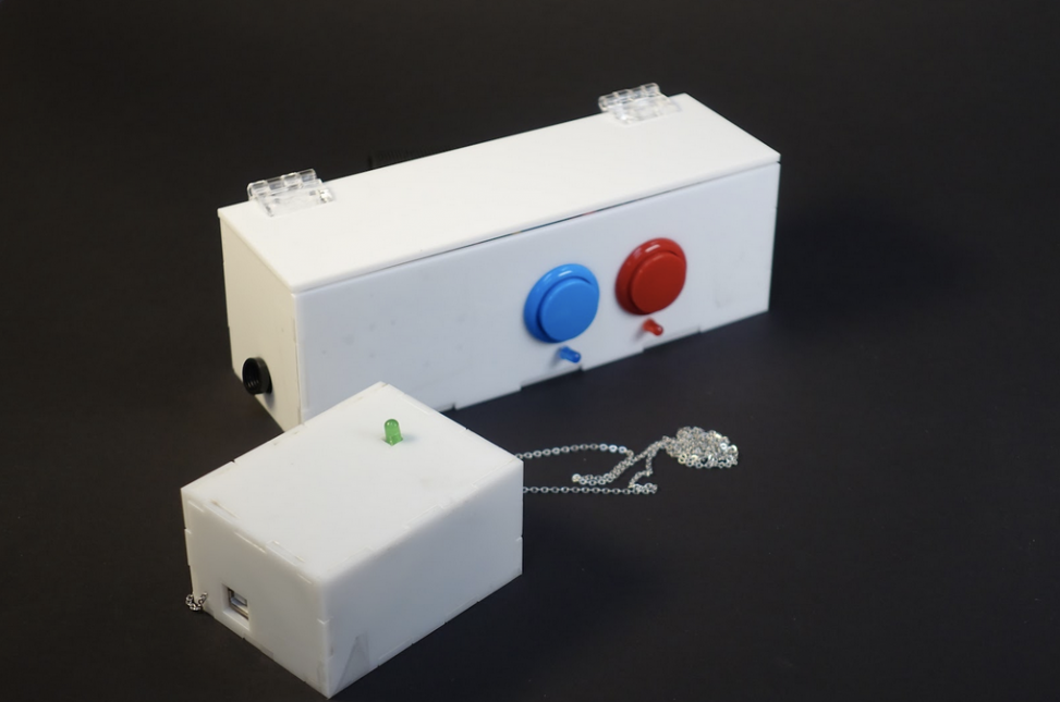
The ICD captures ‘inspiration’ in two different ways- through a picture taken on a small camera or through a voice memo recorded on an audio recorder. The ICD is meant to do this while being as accessible as possible for Mary; the device is split into two parts (a remote controller and a necklace) to make it easy for her to interact with. At the mere press of a button, Mary can take a picture of whatever she is currently facing or turn on a voice recorder on her neck to quickly capture what’s on her mind for future use.
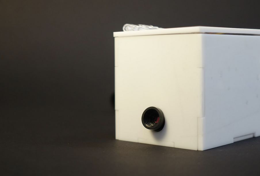
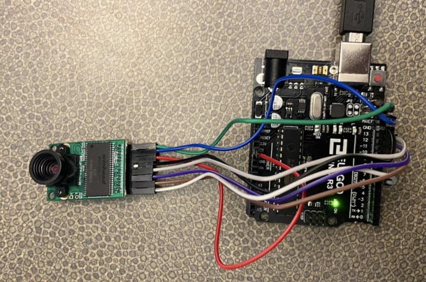
Camera component of the ICD’s remote controller
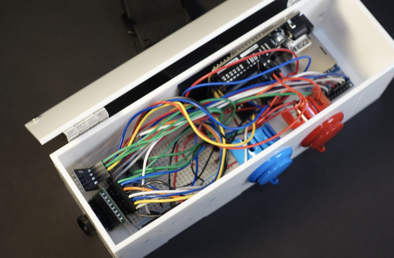
Inside the remote you’ll notice various wires as well as an Arduino Uno and a transceiver on the left near the camera
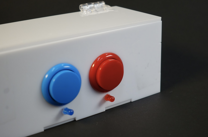
Top view of the remote controller, featuring two buttons with their LED lights meant to indicate current remote activity
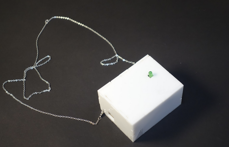
The necklace part of the ICD featuring a green LED
The above video is a compilation of clips relating to the ICD’s capabilities.
Image of Juan’s hand that was captured in the ICD demo video.
Narrative
While Mary is out shopping, she notices that a beautiful unfamiliar kind of bird has perched itself on a table in front of her. She pushes the ICD’s red button to take a picture of the bird so she could find out what type of bird it is later. After doing so, she decides to write something about the bird.
Later in the week, she suddenly gets a fantastic idea for a short story while she’s out and about in Pittsburgh. To ensure she doesn’t forget this idea, she presses the ICD’s blue button and says her idea out loud. She then presses the button again to stop and save the recording. Hours later, Mary uploads the file on her computer, listens to her voice memo, and starts getting to work on an amazing story.
Prototype and Process
Our prototype was broken into four parts so that we could test each component before combining them.
The four components included the remote control, the microphone, the camera, and the necklace. The remote control included large buttons connected to LEDs and wireless transmitters, the microphone and the camera were each attached to an SD card, and the necklace included a casing for internal components and a chain.
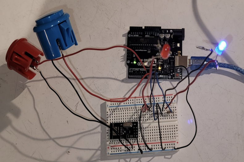
The remote control component of the ICD prototype
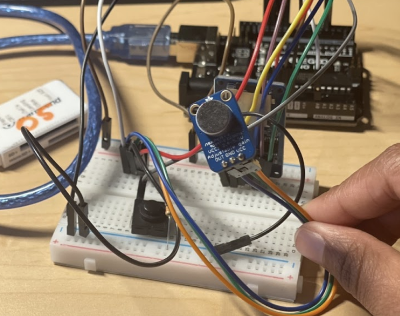
The microphone component of the ICD prototype
The camera component of the ICD prototype
The necklace component of the ICD prototype
The above video showcases the ICD’s simple user interface.
Prototyping
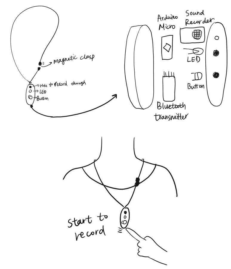
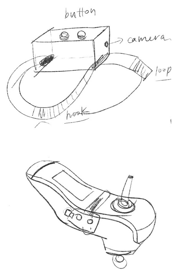
The initial sketches for the necklace part of the ICD
Through our interview with Mary, we found that she is creative and a writer but cannot write down her thoughts quickly, so we created a solution that would allow her to record herself the moment she receives inspiration.
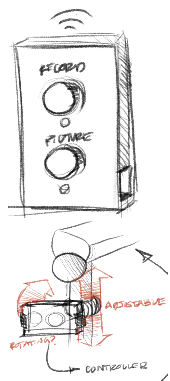
The initial sketch for the remote control part of the ICD
After talking with Mary about our initial sketches and solutions, she suggested that we also include a camera capability because she needs the help of someone else to use her phone camera. We also decided to create a separate remote that housed the camera but also triggered the microphone in the necklace wirelessly to make it more accessible for Mary.
The initial sketch for the attachment of remote
We were trying to figure out the best way to attach the remote to the wheelchair so that it would be easy for Mary to press to record her life. We found that it might be best for remote attachment works like a watch to fix on the wheelchair controller.
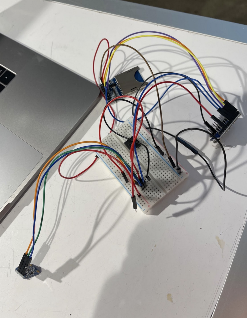
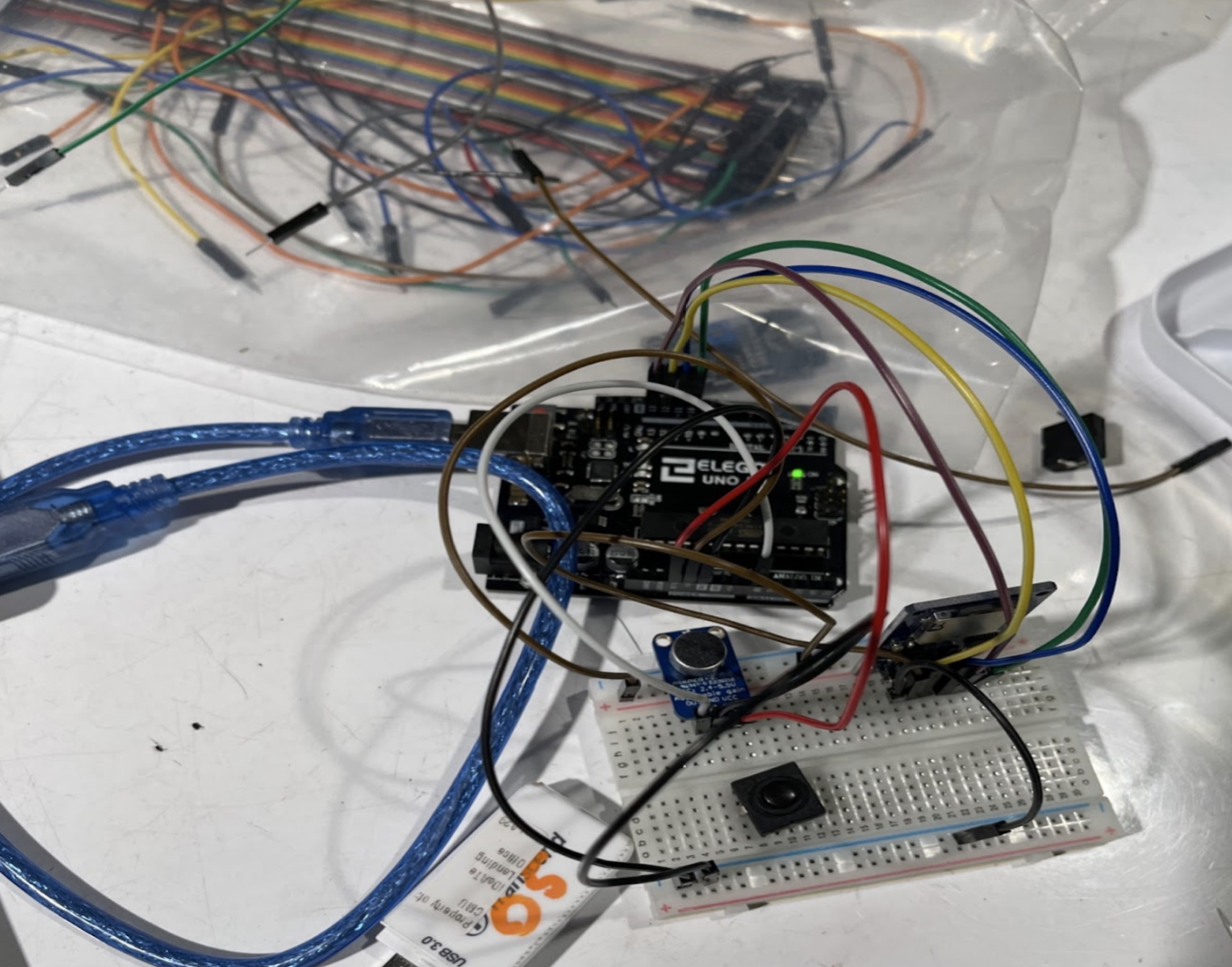 Started a simple setup to work on the microphone component using a microsd card reader module and a microphone module
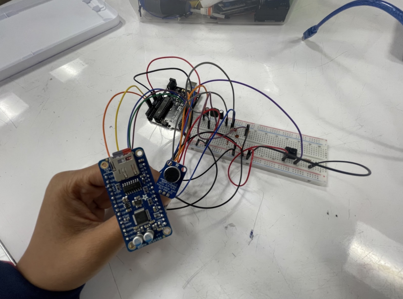
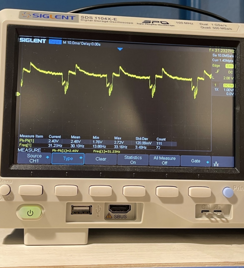 Upon recording the audio noticed that there was a lot of noise. In order to investigate where the noise was coming from we hooked the output of the microphone to an oscilloscope. With some testing we realized that the noise was coming from writing to the SD card reader.
During the prototype critique, we asked Mary to interact with the microphone set up, focusing on how she would insert and remove the microsd card from the reader. We found that reader module was not optimized for Mary’s hands as the sd card was too small and the push mechanism to remove was difficult. And so, we invested in a larger SD card reader.
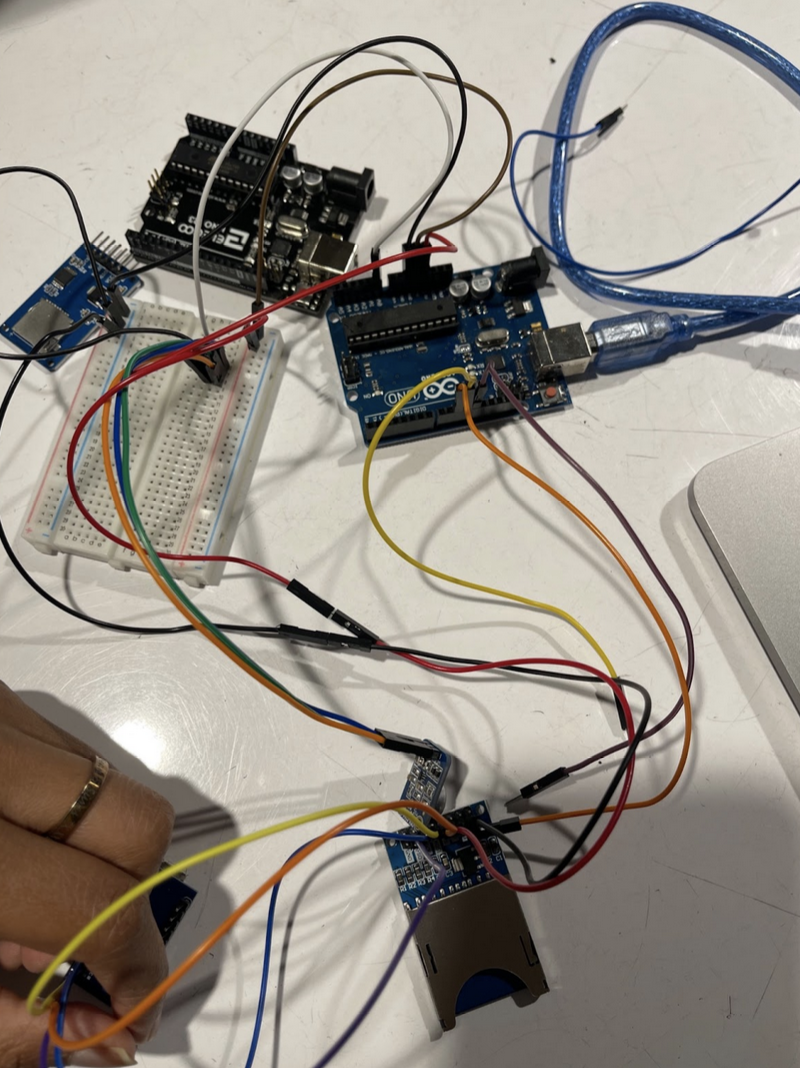
Unfortunately, the noise still persisted. We switched the arduino uno for an arduino pro micro to see if the board made any difference. Our final design would also use a pro micro as it would allow the microphone to fit in the necklace holder.
The above change did not fix the noise either. As a last resort we scrapped the SD card readers and invested in a module(vs1053) that had the optimizations required to cleanly record audio. Given more time we would have fully recorded audio with little noise, but instead the audio files were written to the SD card without any audio.
There were also some issues with other components; a moment of frustration regarding the transceivers in our project should be mentioned: Juan spent an unideal amount of time attempting to debug issues with the wireless transceivers. Unsure if the issue was hardware, software, or wiring-related, hours were lost on his part trying to fix the transceiver problem and could’ve gone towards other aspects of the project. This narrow focus on solving the problem in retrospect was a mistake- the time spent trying to resolve the issue (which ended up being due to a broken transceiver) could have instead been spent assisting Sumayya with the voice recorder component of the project. By the time the solution to the transceiver problem was discovered, it was simply too late to assist with other aspects of the project. This served as a learning experience regarding debugging physical computing components as well as knowing when to cut your losses. In addition, we also had some issues with the ICD’s physical case.
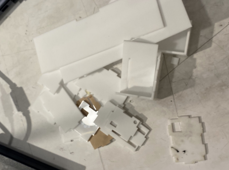
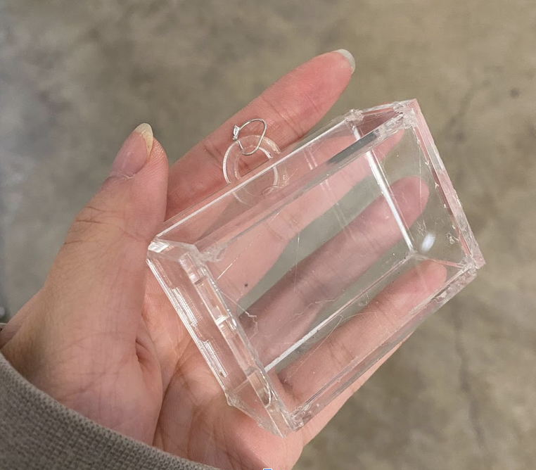
The failed versions of the cases
To make sure the two cases are easy for Mary to use, we have to make them both as small and light as possible. Therefore, every electronic component should be located at its specific place. We did a lot of tests to decrease the size.
Prototyping Process Findings
Though we each worked on separate components of the ICD, the prototyping process helped teach us a variety of lessons not only about our individual components, but also about working on a physical computing project in general. From questions regarding how our overall project would be powered to what final form it would take, there were several moments throughout the prototyping process where we had to answer questions as a team rather than individually. This was somewhat surprising-even though we were all working on vastly different pieces of technology, the choices we each made on our parts had effects on the overall team project that were sometimes subtle and other times drastic. It was partly due to this that our final version was incomplete- we didn’t truly begin accommodating each other’s work until the final stages of the project. By that point, it was too late to make some much needed adjustments, such as making the ICD’s case less sharp and improving the ICD’s attachment to a wheelchair which were recommended to us from our critiques. We did not intentionally ignore this feedback, but unfortunately we ran out of time to address most of it.
Gantt Tracking
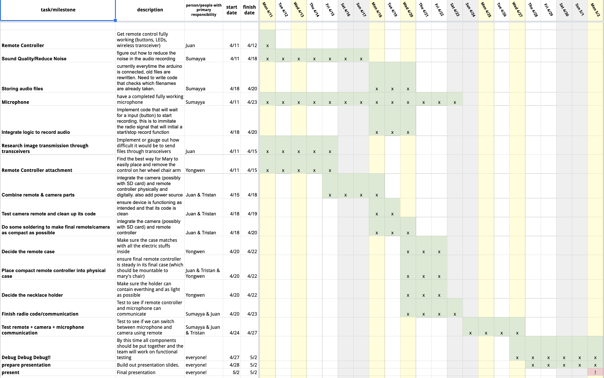
Our team’s Gantt chart- visualizing our originally planned project schedule
Overall, we were able to roughly follow our Gantt chart to about 75% accuracy. Divergences from our schedule were mainly due to longer than expected debugging times, slow-arriving components that were stuck in transit for longer than preferred, as well as other miscellaneous issues such as group members falling ill during some days.
Conclusions and Lessons Learned
Feedback
Some feedback that stood out to us were the following:
- “Develop ergonomics, far reach in objectives file transferring”
- “There are several steps involved in retrieving files; but, those could be incorporated into an end-of-day routine. The device is a bit large and the sharp corners could be uncomfortable.”
- “They really should have considered how their client would use this and added some personality of their client into it.”
- “A good idea. Make attachment to chair more stable.”
The reason why these pieces of feedback stood out to us was because they reinforced ongoing discussions we were already having regarding the direction of our project. Adding “personality” and making file transferring simpler, for instance, were goals we wanted to achieve but didn’t really figure out how to do so. This was partly due to delays in our planned schedule, and ultimately by the time we shifted our focus to the form of our project there was too little time to implement some of the recommended changes. That being said, all of the feedback received was insightful and extremely helpful for possible future iterations of our project.
Thoughts on Remote Work
In general, it was smooth to work remotely. At the first beginning, we lost contact with Mary but we got into a collaboration with her successfully soon. Sometimes we did different parts of the project individually but we still cared about the work from each other. Everyone put a lot of effort into this project and often continued working after class alone. If we had another chance to work together remotely, it might be a good way for better collaboration by updating the process once after work.
Takeaways from working with Mary
This journey looked like we were doing a device to help Mary, but literally it was Mary who inspired us a lot. She never gave up her love towards life though her mobility was limited. She had her own hobbies and work, her life was so adorable and she got a lot of sense of achievement during her tutorial work. “I really enjoy my life.” Mary said in her first interview with us. At that time we four were all touched by her strong positive vibe.
Concluding Thoughts
Even though our final prototype was somewhat distant from our original vision, the process we all went through while working on the prototype was very educational and insightful. We each learned different things about not just our components, but about the process of prototyping a physical computing project as well as working as a team in general.
Given a second go at the project knowing what we know now, our biggest changes would have to do with how we worked on the project in general. Our decision to split the ICD into four separate parts, one for each member, seemed like an obvious one at first but in retrospect proved to be a hindrance in the final stages of our prototyping process. Since we were all the resident “expert” on the part we were working on within the group, having a group member absent severely hampered our ability to move the project forward. This hurt us a lot after carnival, where some members of the group got sick and as a result had to miss some work sessions- negatively impacting the whole group’s progress.
A possible solution would be to assign two members to each component. This would greatly help with the aforementioned absence problem, and it would have also had positive effects on each component itself since there would be two minds tasked to making progress on each part instead of just one. Additionally, we would also resolve certain prototype issues, like choosing a battery and final form, as soon as possible instead of saving that for the very end given the importance of accessibility for our client.
Some other takeaways include establishing a debugging process for components early on, not underestimating the soldering process, properly gauging capabilities/knowledge early on in the process, and removing/combining features earlier! These takeaways were largely individual- Juan’s takeaway (the debugging process) was the result of too many hours spent trying to debug what ended up being broken components. Sumayya’s, on the other hand, centered on her experience tackling the complicated voice recording system. Instead of pivoting to a different direction earlier, her various attempts to get the component working backfired as other components that were behind in terms of progress would have made major use of an extra mind. Yongwen and Tristan also had their fair share of takeaways stemming from their assigned components. Overall, however, we can simply say that each one of us learned something valuable about our very own approaches to different problems.
Technical details
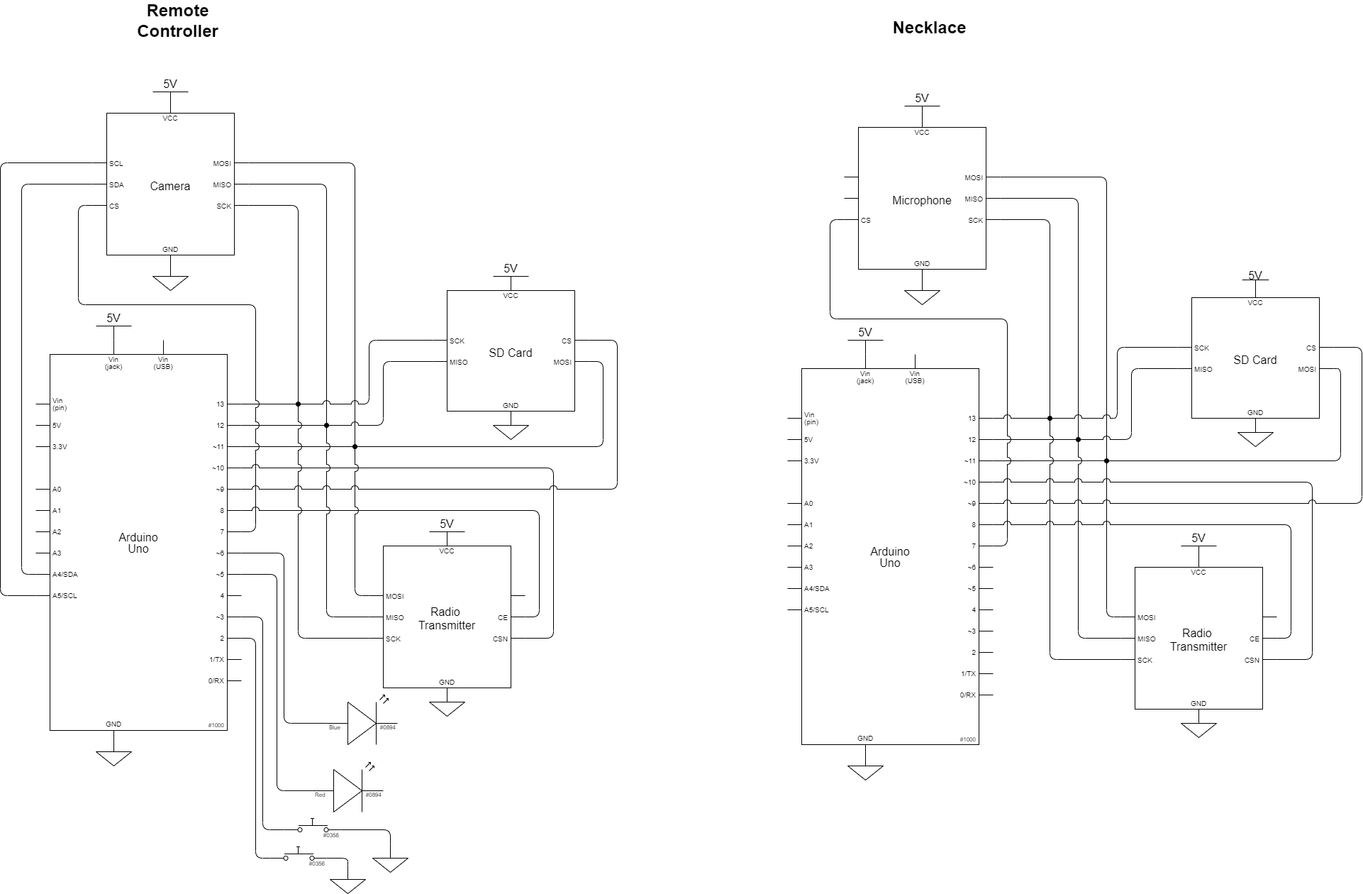
Diagrams
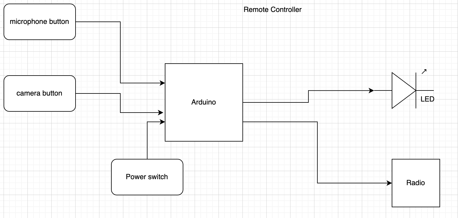
Remote Controller Diagram
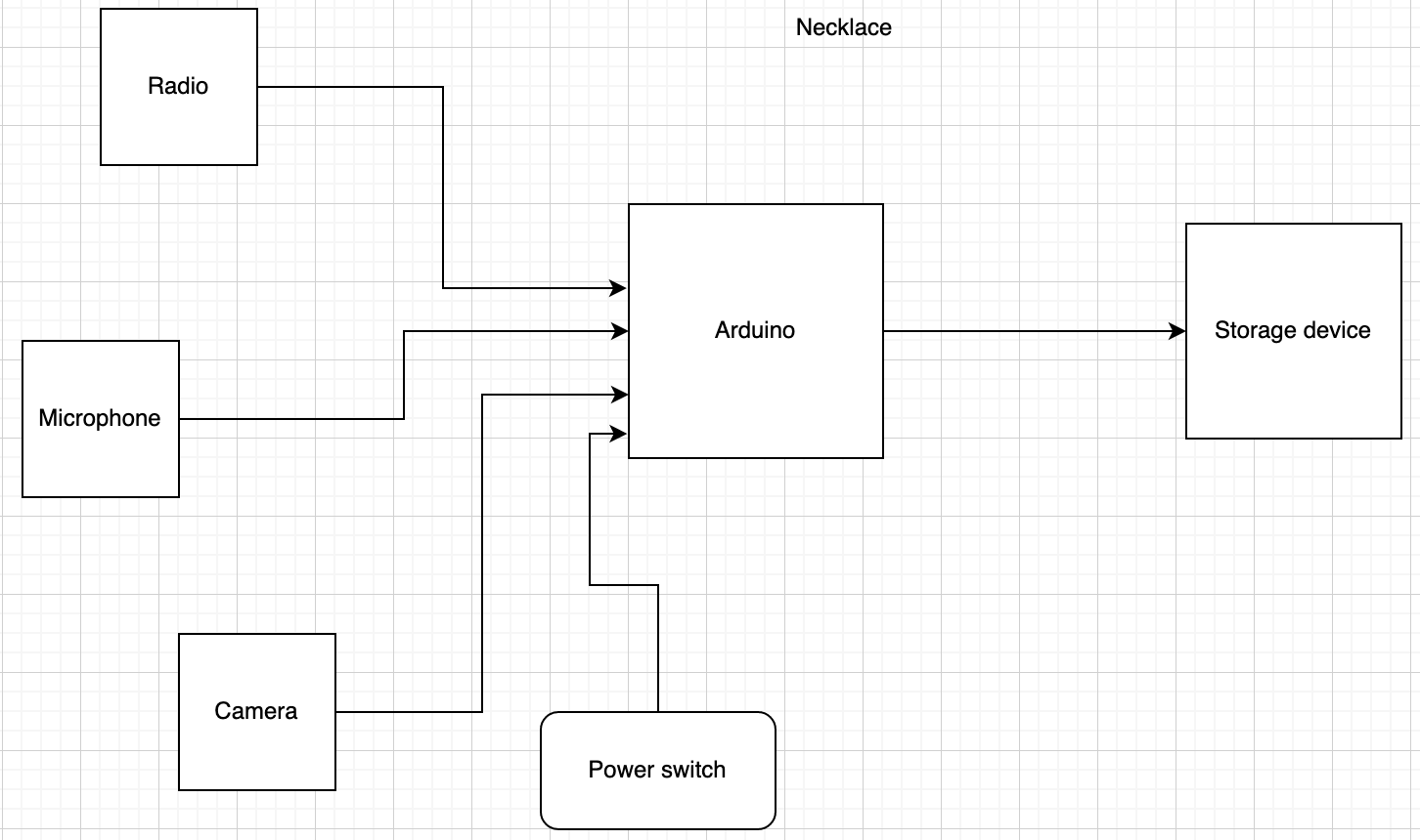
Necklace Diagram
Code
// Thanks to ArduCAM Mini demo (C)2018 by Lee, found at http://www.ArduCAM.com
/*Image Capture Device - Remote/Camera Code,
Juan Meza, Tristan Hineman
This code operates the remote's various functionalities, including
how it takes user input, how it sends data wirelessly, and how it takes
and saves images taken from the device.
*/

//SPI Mosi-11, Miso-12, Sck-13

#include <nRF24L01.h>
#include <RF24.h>
#include <EEPROM.h>

#include <Wire.h>
#include <ArduCAM.h>
#include <SPI.h>
#include <SD.h>
#include "memorysaver.h"

#define BUTTON 8
#define BUTTON_BLUE 2
#define LED_BLUE 6 //blue LED
#define LED_RED 5 //red LED
#define SD_CS 9
#define FRAMES_NUM    0x00

const byte address[6] = "42069";
bool isButtonPressed = false;
unsigned long buttonTime;
int ButtonPresses = 0;

// set pin 7 as the slave select for the digital pot:
const int CS = 7;

RF24 radio(3, 4); // CE, CSN

//camera
//This demo can only work on OV5640_MINI_5MP_PLUS or OV5642_MINI_5MP_PLUS platform.
#if !(defined (OV2640_MINI_2MP_PLUS))
#error Please select the hardware platform and camera module in the ../libraries/ArduCAM/memorysaver.h file
#endif


bool is_header = false;
int total_time = 0;

#if defined (OV2640_MINI_2MP_PLUS)
ArduCAM myCAM( OV2640, CS );
#endif

uint8_t read_fifo_burst(ArduCAM myCAM);

void setup() {

  pinMode(BUTTON, INPUT_PULLUP);
  pinMode(BUTTON_BLUE, INPUT_PULLUP);
  pinMode(LED_BLUE, OUTPUT);
  pinMode(LED_RED, OUTPUT);

  buttonTime = millis();

  radio.begin();
  radio.openWritingPipe(address);
  radio.setPALevel(RF24_PA_MIN);
  radio.stopListening();

  // camera
  uint8_t vid, pid;
  uint8_t temp;

#if defined(__SAM3X8E__)
  Wire1.begin();
#else
  Wire.begin();
#endif

  Serial.begin(115200);

  Serial.println(F("ArduCAM Start!"));
  // set the CS as an output:
  pinMode(CS, OUTPUT);
  digitalWrite(CS, HIGH);
  // initialize SPI:
  SPI.begin();
  //Reset the CPLD
  myCAM.write_reg(0x07, 0x80);
  delay(100);
  myCAM.write_reg(0x07, 0x00);
  delay(100);


  while (1) {
    //Check if the ArduCAM SPI bus is OK
    myCAM.write_reg(ARDUCHIP_TEST1, 0x55);
    temp = myCAM.read_reg(ARDUCHIP_TEST1);
    if (temp != 0x55)
    {
      Serial.println(F("SPI interface Error!"));
      delay(1000); continue;
    } else {
      Serial.println(F("SPI interface OK.")); break;
    }
  }


#if defined (OV2640_MINI_2MP_PLUS)
  while (1) {
    //Check if the camera module type is OV2640
    myCAM.wrSensorReg8_8(0xff, 0x01);
    myCAM.rdSensorReg8_8(OV2640_CHIPID_HIGH, &vid);
    myCAM.rdSensorReg8_8(OV2640_CHIPID_LOW, &pid);
    if ((vid != 0x26 ) && (( pid != 0x41 ) || ( pid != 0x42 ))) {
      Serial.println(F("ACK CMD Can't find OV2640 module!"));
      delay(1000); continue;
    }
    else {
      Serial.println(F("ACK CMD OV2640 detected.")); break;
    }
  }

#endif


  //Initialize SD Card
  while (!SD.begin(SD_CS))
  {
    Serial.println(F("SD Card Error!")); delay(1000);
  }
  Serial.println(F("SD Card detected."));
  //Change to JPEG capture mode and initialize the OV5640 module
  myCAM.set_format(JPEG);
  myCAM.InitCAM();
  myCAM.clear_fifo_flag();
  myCAM.write_reg(ARDUCHIP_FRAMES, FRAMES_NUM);
}


void loop() {

  myCAM.flush_fifo();
  myCAM.clear_fifo_flag();
#if defined (OV2640_MINI_2MP_PLUS)
  myCAM.OV2640_set_JPEG_size(OV2640_1600x1200);
#endif

  int buttonVal = digitalRead(BUTTON);
  //Serial.println(buttonVal);
  //as a reminder, when a button is being pressed buttonVal turns to zero

  int buttonBlueVal = digitalRead(BUTTON_BLUE);

  if (buttonVal == 0) {
    Serial.println("red is being pressed");
    digitalWrite(LED_RED, HIGH);

    myCAM.start_capture();
    Serial.println(F("start capture."));
    total_time = millis();
    while ( !myCAM.get_bit(ARDUCHIP_TRIG, CAP_DONE_MASK));

    Serial.println(F("CAM Capture Done."));
    total_time = millis() - total_time;
    Serial.print(F("capture total_time used (in miliseconds):"));
    Serial.println(total_time, DEC);
    total_time = millis();

    read_fifo_burst(myCAM);
    total_time = millis() - total_time;
    Serial.print(F("save capture total_time used (in miliseconds):"));
    Serial.println(total_time, DEC);
    //Clear the capture done flag
    myCAM.clear_fifo_flag();
    digitalWrite(LED_RED, LOW); //turn off to signify that image has been taken

  }

  if (buttonBlueVal == 0) {
    Serial.println("blue is being pressed");
    const char text[] = "ACTIVATE NECKLACE";
    radio.write(&text, sizeof(text));
    digitalWrite(LED_BLUE, HIGH);
    delay(500); //do some blinking first
    digitalWrite(LED_BLUE, LOW);
  }

  if ((buttonVal == 0 || buttonBlueVal == 0) && millis() - buttonTime >= 500) { //button is being pressed for reasonable time

    //Serial.println(millis()-buttonTime);
    ButtonPresses++;
    buttonTime = millis(); //reset buttonTime for next button press
    //Serial.println("Button is being pressed.");
    Serial.println("Button has been pressed this many times:");
    Serial.println(ButtonPresses);

  }

  else {
    //Serial.println("Button is NOT being pressed.");
  }

  if (ButtonPresses >= 1) {
    //digitalWrite(LED1,HIGH); //on, LOW for off

  }

  if (ButtonPresses == 2) {
    //digitalWrite(LED2,HIGH);

  }

  if (ButtonPresses > 2) { //more than 2,  reset!
    Serial.println("TIME TO RESET");

    digitalWrite(LED_BLUE, LOW);
    digitalWrite(LED_RED, LOW);

    delay(300); //do some blinking first

    digitalWrite(LED_BLUE, HIGH);
    digitalWrite(LED_RED, HIGH);

    delay(300);

    digitalWrite(LED_BLUE, LOW);
    digitalWrite(LED_RED, LOW);

    ButtonPresses = 0; //reset total button presses
  }
}

uint8_t read_fifo_burst(ArduCAM myCAM)
{
  uint8_t temp = 0, temp_last = 0;
  uint32_t length = 0;
  static int i = 0;
  static int k;
  char str[16];
  File outFile;
  byte buf[256];
  length = myCAM.read_fifo_length();
  Serial.print(F("The fifo length is :"));
  Serial.println(length, DEC);

  if (length >= MAX_FIFO_SIZE) //8M
  {
    Serial.println("Over size.");
    return 0;
  }
  if (length == 0 ) //0 kb
  {
    Serial.println(F("Size is 0."));
    return 0;
  }

  myCAM.CS_LOW();
  myCAM.set_fifo_burst();//Set fifo burst mode
  i = 0;
  while ( length-- )
  {
    temp_last = temp;
    temp =  SPI.transfer(0x00);
    //Read JPEG data from FIFO
    if ( (temp == 0xD9) && (temp_last == 0xFF) ) //If find the end ,break while,
    {
      buf[i++] = temp;  //save the last  0XD9
      //Write the remain bytes in the buffer
      myCAM.CS_HIGH();
      outFile.write(buf, i);
      //Close the file
      outFile.close();
      Serial.println(F("OK"));
      is_header = false;
      myCAM.CS_LOW();
      myCAM.set_fifo_burst();
      i = 0;
    }
    if (is_header == true)
    {
      //Write image data to buffer if not full
      if (i < 256)
        buf[i++] = temp;
      else
      {
        //Write 256 bytes image data to file
        myCAM.CS_HIGH();
        outFile.write(buf, 256);
        i = 0;
        buf[i++] = temp;
        myCAM.CS_LOW();
        myCAM.set_fifo_burst();
      }
    }

    else if ((temp == 0xD8) & (temp_last == 0xFF))
    {
      is_header = true;
      myCAM.CS_HIGH();
      //Create a avi file
      EEPROM.get(0, k);
      k = k + 1;
      EEPROM.update(0, k);

      Serial.print("Picture number=");
      Serial.println(k);
      itoa(k, str, 10);
      strcat(str, ".jpg");

      //Open the new file
      outFile = SD.open(str, O_WRITE | O_CREAT | O_TRUNC);

      if (! outFile)
      {
        Serial.println(F("File open failed"));
        while (1);
      }

      myCAM.CS_LOW();
      myCAM.set_fifo_burst();
      buf[i++] = temp_last;
      buf[i++] = temp;
    }
  }
  myCAM.CS_HIGH();
  return 1;
}
/*
* Thanks to Dejan Nedelkovski, www.HowToMechatronics.com
/*Image Capture Device - "Necklace" Code,
Juan Meza
This code operates our necklace's wireless capabilities.
It where the necklace should look for a signal and
performs an action after finding said signal.
*/


#include <SPI.h>
#include <nRF24L01.h>
#include <RF24.h>
#include <string.h>

#define LED_TEST 3 //green temp LED

const byte address[6] = "42069";
RF24 radio(7, 8); // CE, CSN

void setup() {

  pinMode(LED_TEST,OUTPUT);

  Serial.begin(115200);
  radio.begin();
  radio.openReadingPipe(0, address);
  radio.setPALevel(RF24_PA_MIN);
  radio.startListening();

  Serial.println("Receiver is ready to receive...");
  digitalWrite(LED_TEST,HIGH);
  delay(300);
  digitalWrite(LED_TEST,LOW);

}

void loop() {

  if (radio.available()) {
    char text[32] = "";
    radio.read(&text, sizeof(text));
    Serial.println(text);

    String key = "ACTIVATE NECKLACE";

    if (String(text) == key){
      //blink LED!
      digitalWrite(LED_TEST,LOW);
      digitalWrite(LED_TEST,LOW);
      delay(300);
      digitalWrite(LED_TEST,HIGH);
      digitalWrite(LED_TEST,HIGH);
      delay(300);
    }
  }

}
Special thanks to Professor Zacharias and everyone else who helped us get so far!