The SunLight
Cassie Rausch
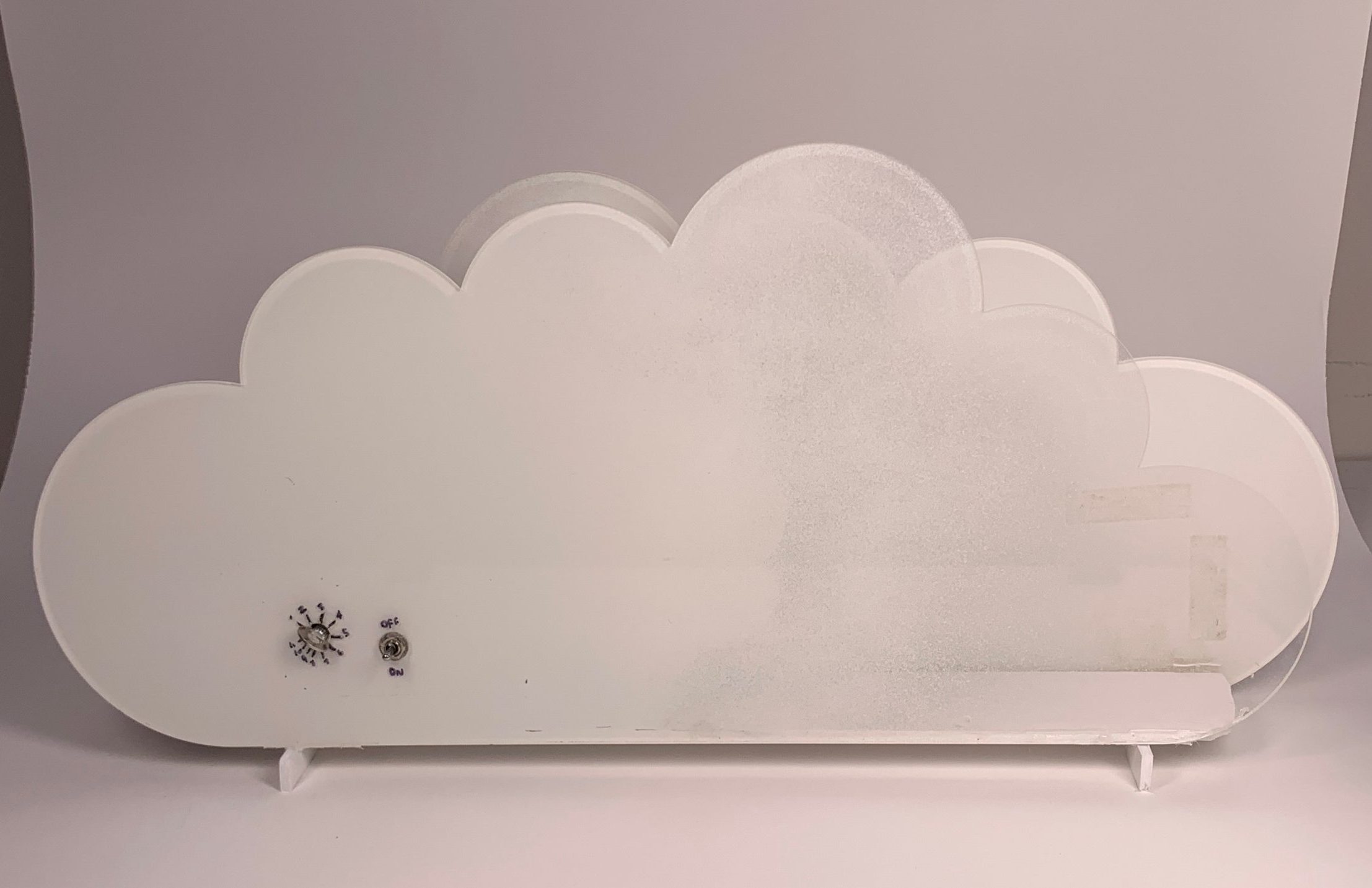
The SunLight is an alarm clock that relies on a bright light to wake up the user rather than a loud noise.
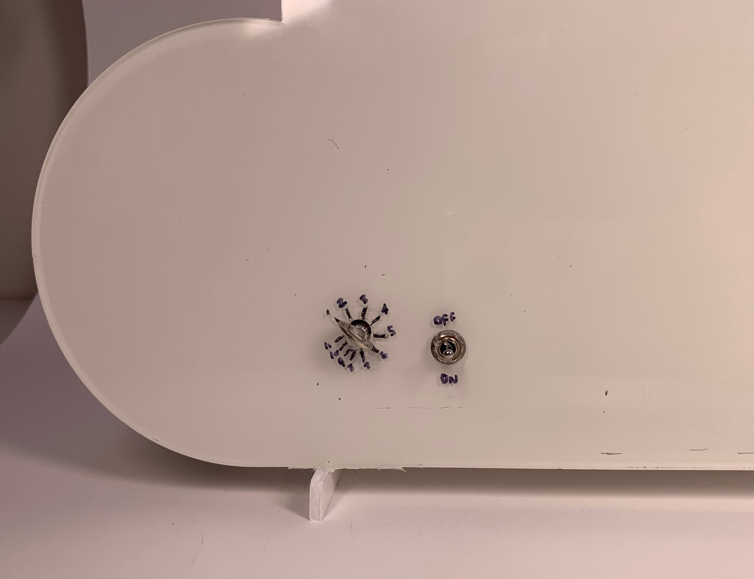
I chose to keep the controls very simple and almost utilitarian-looking.
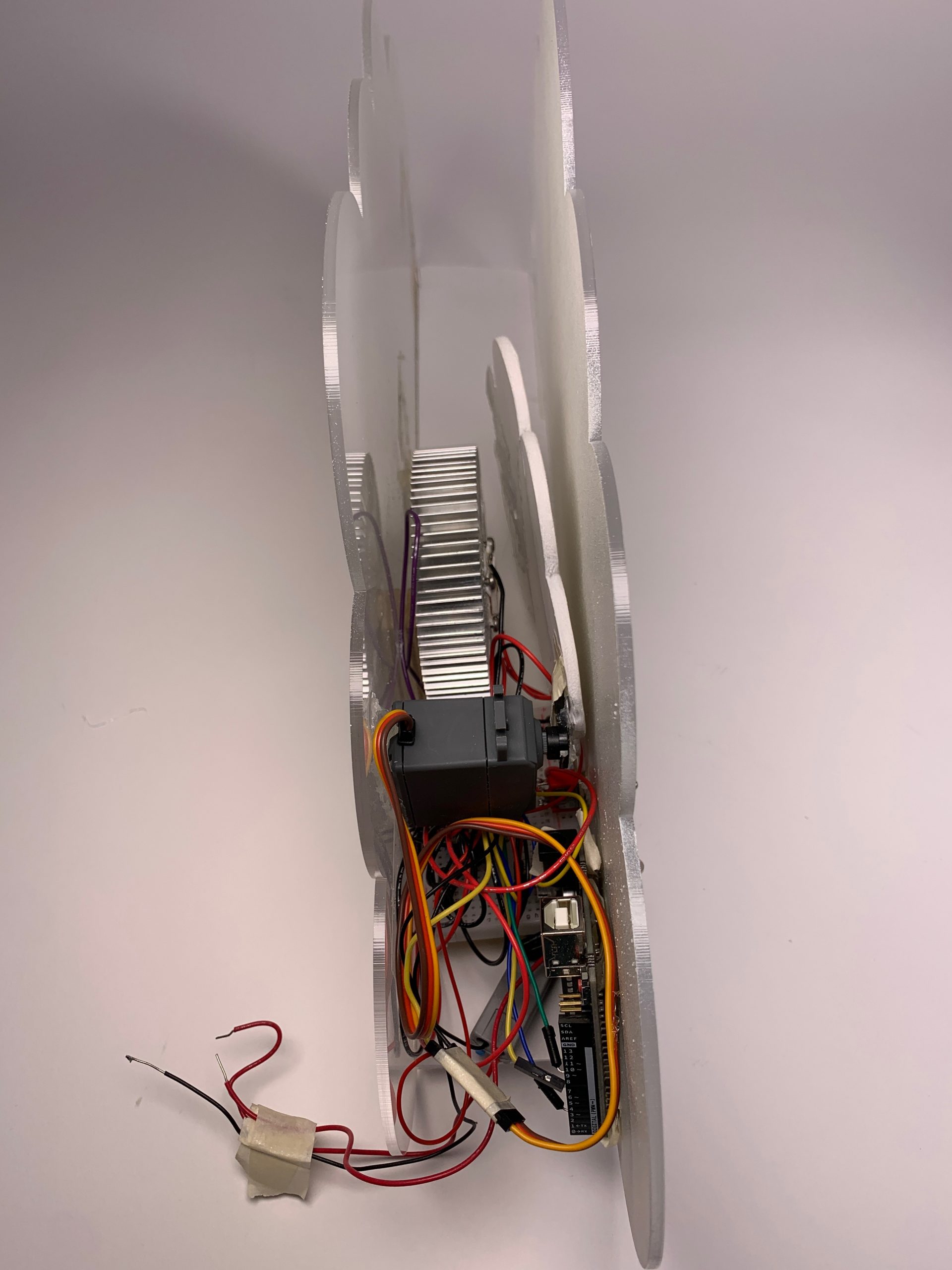
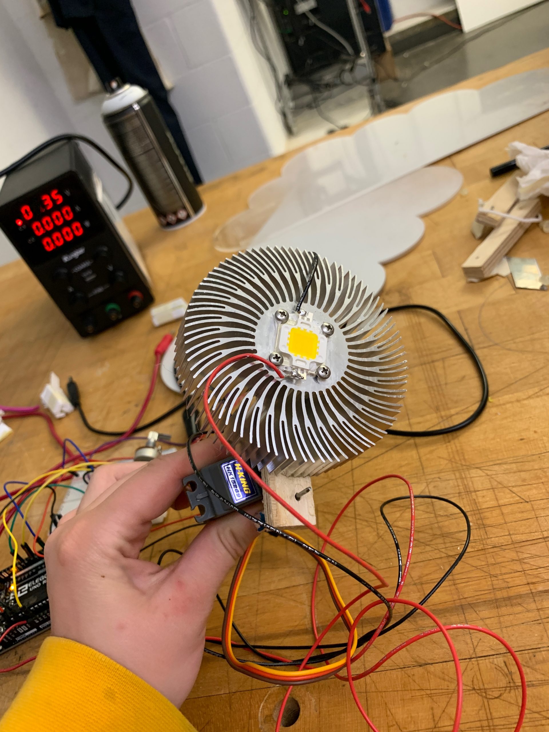
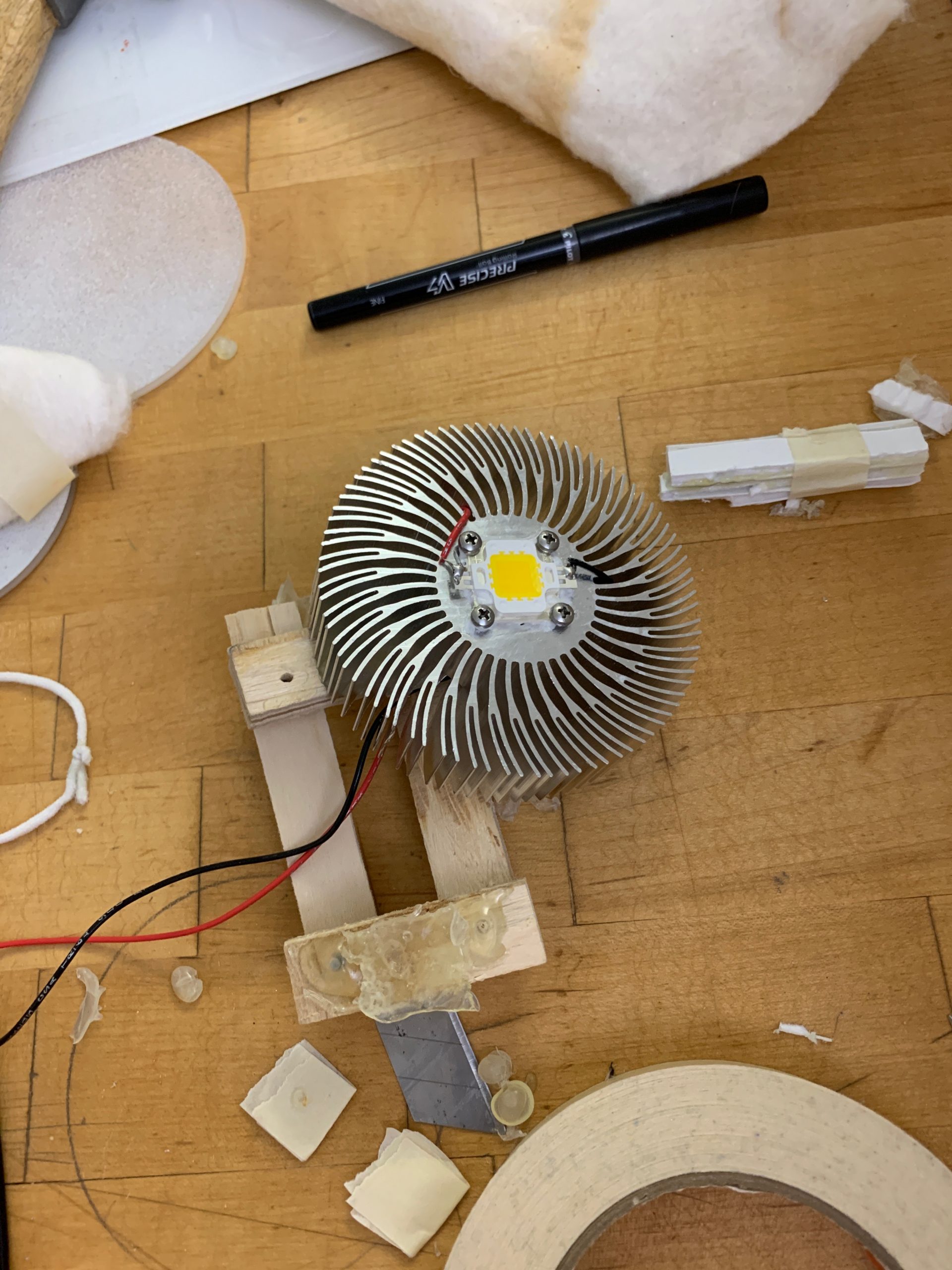
A side view of the SunLight showing all of the electronics.
Process
When I was designing the exterior of my alarm clock, I originally wanted to have two separate parts, the light made to look like a sun and the clouds that it would emerge from. The clouds would only block the first half of the suns arc and the sun would be moving from the point that the alarm was set until the end.
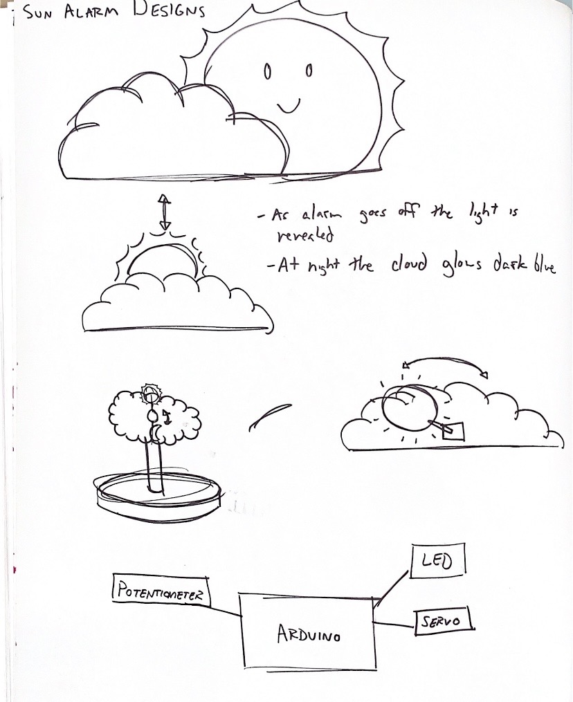
Sketches of potential sun alarm ideas.
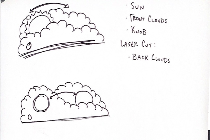
More sketches of potential sun alarms, closer to what I originally had planned for the project.
I knew when I was designing this project that I wanted the alarm to be a physical movement of the light or a cover or something similar instead of the whole system being digital. The idea of a light blinding you in the morning to wake you up is pretty harsh, so I wanted to make this a more enjoyable and gradual experience for the user.
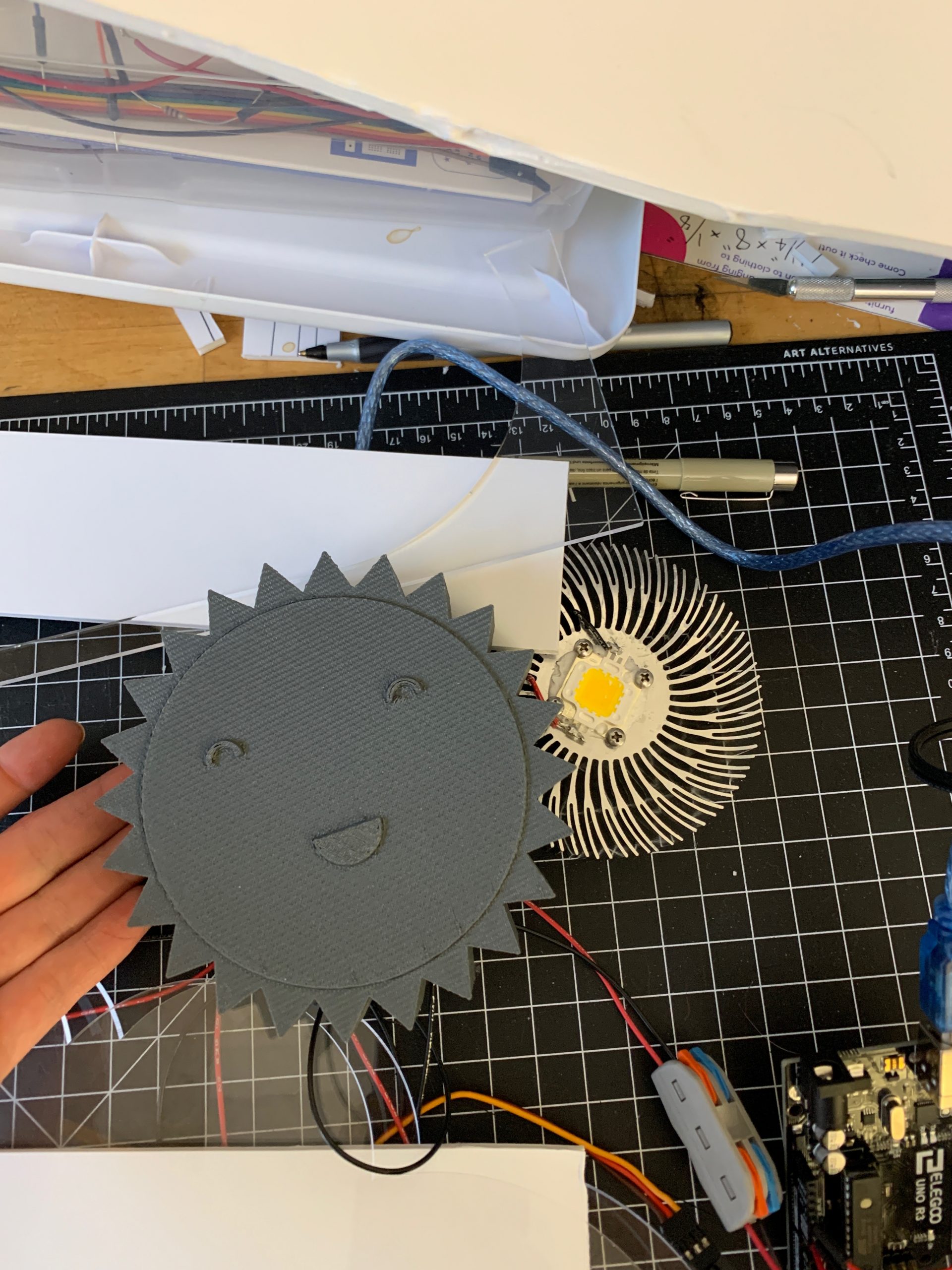
Sun cover for the light that I designed in Solidworks and 3D printed in PLA plastic.
I was pretty excited for my cute sun cover, but I realized that I would have to drill holes to let light out because I made the cover too thick. The fit was also a bit snug, but I could get the LED in and out with some effort.

The cloud covers sitting out drying after I spray painted them.
Spray painting the cloud covers took a bit of practice before I knew that I could get the gradient down. I didn’t have much experience with spray paint, but I had a lot of fun painting them.
I made two big decisions during my design process that led me to my final result. First was the decision to make the whole shape a cloud and make the gradient from dark to light using paint. When I was modeling my ideas in Solidworks, I realized that it would be difficult to make something with more volume because of the size of my project. 3D printing a cloud like shape would be too large to fit on the print bed and if I make a mistake it’s expensive and time consuming to reprint. Instead I decided to use the laser cutter to save time and made the whole shape a cloud with the electronics and light sandwiched in the middle.
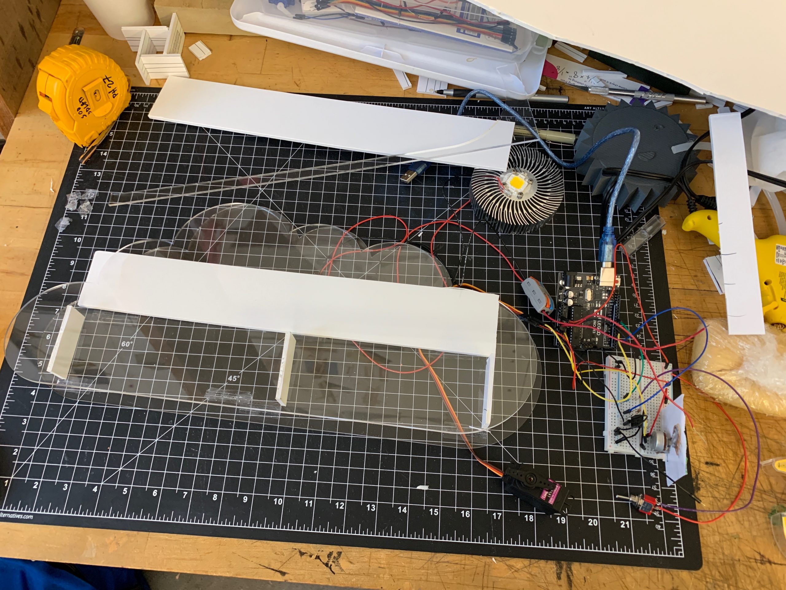
Deciding how I’m going to lay out my design and make the sandwich idea work.
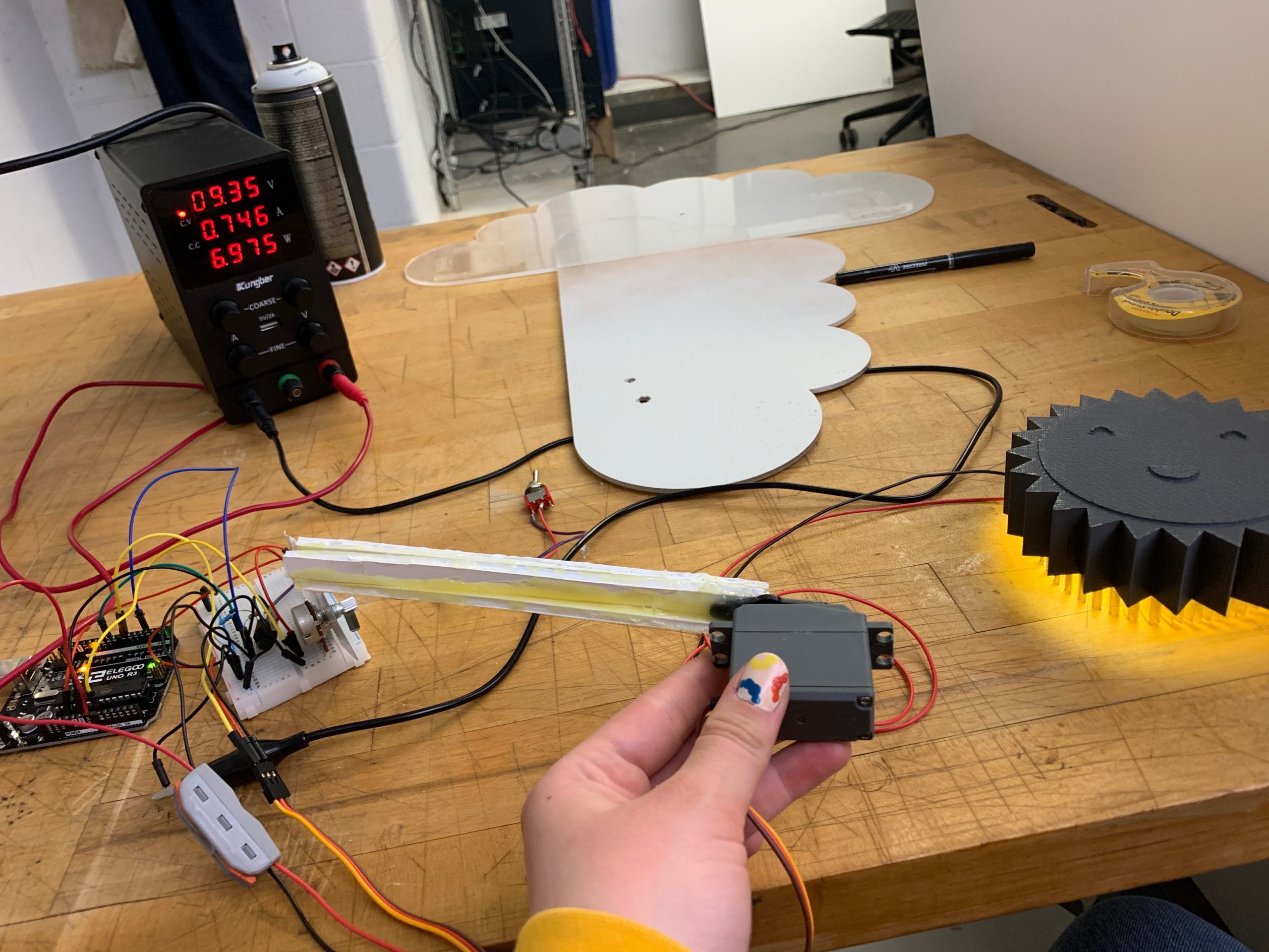
My next big decision in my process was deciding to put a cover on the servo to block the light rather than attaching the light to the servo. When I was working on the mechanism to move the light I really struggled to get the servo to move the small amounts that I needed to get the slow sweep that I wanted. This was because the heat synch on the LED added a ton of weight that the little servo could not handle. So I tried a few different attachment styles for the LED to the servo (even making a four bar mechanism to better support the weight out of finishing nails and wood scraps) but instead chose to make a much lighter cloud to cover the LED that would be attached to the servo.
First attempt to connect the light to the servo using hot glue and foam board scraps.
Second attempt to attach the LED to the servo. I shortened the arm that the servo uses to provide more mechanical advantage and used a stronger material.
Third attempt to connect the servo to the LED. I made an overly-complicated four bar mechanism that I thought would solve the issue.
Discussion
I really enjoyed this project and the creative freedom that it allowed me to make whatever I want. As someone who is constantly thinking of things that I’d like to make or try out, I don’t often have the time or materials to be able to make many of my ideas, so I’m glad that I got to try this one.
This project mainly taught me that I take much more time when considering the code than the mechanical aspects of the project, and I also find the code much less interesting. I remember spending large amounts of time debugging my code and making it function correctly and it was one of the most infuriating experiences. Especially when working with relatively cheap electronic parts and my limited knowledge of electronics, it was difficult to tell at times if the issue was coding, human error, wiring, or the parts. However I do remember every step of building the project very well. I really enjoyed designing and building it, although I do wish that I had used better time management.
Despite the frustrations, I am very happy with how this project turned out. It ended up looking pretty different than I had originally imagined, but it also pushed me into some minimalist designing that I typically wouldn’t do. It doesn’t function perfectly, but I’m proud of how much I learned while coding and how much I was able to do.
Looking at what others thought of my project, I received the comment that “This is super aesthetically pleasing and I think the design of the clouds/sun is really impressive – it’s similar to storytelling with physical computing.” The idea of storytelling with physical computing really interested me, and I liked the way that this person saw my project. I also received the suggestion that “I think having more controls to alter the light intensity during the day would be useful.” I somewhat worked the idea of the SunLight also working as a lamp into my concept, but due to limited time I didn’t work this in. Although I didn’t consider an additional control to change light levels and I think that could really polish off my design.
I really enjoyed this project, and I plan to continue to make changes to my SunLight. My next step is to integrate the power source into the design and soldering the wires, followed by making the transition from light to dark more seamless, then adding in the lamp function. If I could, I’d like to give the lamp a brightness dial as well as make an option to change color. I would also make the dial to set the hour more accurate and easy to read.
Technical Information
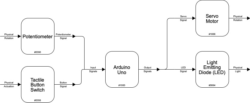
Block Diagram

Schematic
Code
//Project 2: SunLamp
//Cassie Rausch
//pin 7 controls the servo
//pin A0 controls the potentiometer
//pin 3 controls the LED
//pin 9 controls the tactile switch
//Debugging help from Michelle Zhu


#include <Servo.h>
#include <Wire.h>


const int servoPIN = 7;
const int potPIN = A0;
const int ledPIN = 3;
const int switPIN = 9;


Servo sun;

void setup() {
  // put your setup code here, to run once:
  pinMode(potPIN, INPUT);
  pinMode(switPIN, INPUT);
  pinMode(servoPIN, OUTPUT);
  pinMode(ledPIN, OUTPUT);

  sun.attach(7);

  Serial.begin(9600);
}

void loop() {
  //  maxTime = 12 * 60 * 60 * 1000; uncomment this if using as intended and not for demo
  int maxTime = 30 * 1000;
  int servoMax = 180;
  int knobMax = 1023;

  int knobSelection = analogRead(potPIN); // potentiometer reading
  //  int moveTime = 15 * 60 * 1000; uncomment this if using as intended and not for demo
  int moveTime = 15 * 1000;
  int waitTime = maxTime * float(knobSelection / knobMax) - moveTime; // num total runtime ms
  int timeInterval = moveTime / servoMax; // time between each tick movement

  // Actual running

  if (digitalRead(switPIN) == HIGH) { // allowed to begin
    Serial.println("Switch on");
    sun.write(0);
    digitalWrite(ledPIN, HIGH); // turn the light on
    delay (waitTime); // don't do anything

    // start the alarm!
    for (int pos = 0; pos <= servoMax; pos++) {

      if (digitalRead(switPIN) == HIGH) { // 1 = true = keep going!
        delay (timeInterval);
        sun.write(pos);
        Serial.println(pos);
      } else { // 0 = stop the alarm!
        Serial.println("Switch off");
        sun.write(0);
        digitalWrite(ledPIN, LOW);
        return;
      }
    }
  }
}