Introduction
In this class, we worked collaboratively with our client Bill, who has achromatopsia and is sensitive to light. We aimed to create an assistive device to help him with his daily activities. After conducting several interviews with Bill, we learned that he loves cooking but has difficulty determining if the meat is cooked through due to his inability to see color changes. As a result, we decided to create an assistive cooking device to help him cook safely. We aim to provide Bill with a device that will enable him to cook confidently and safely.
What we Built
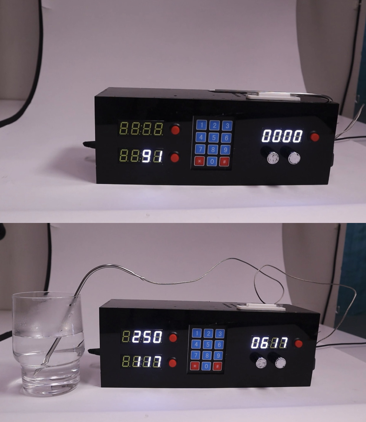
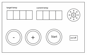
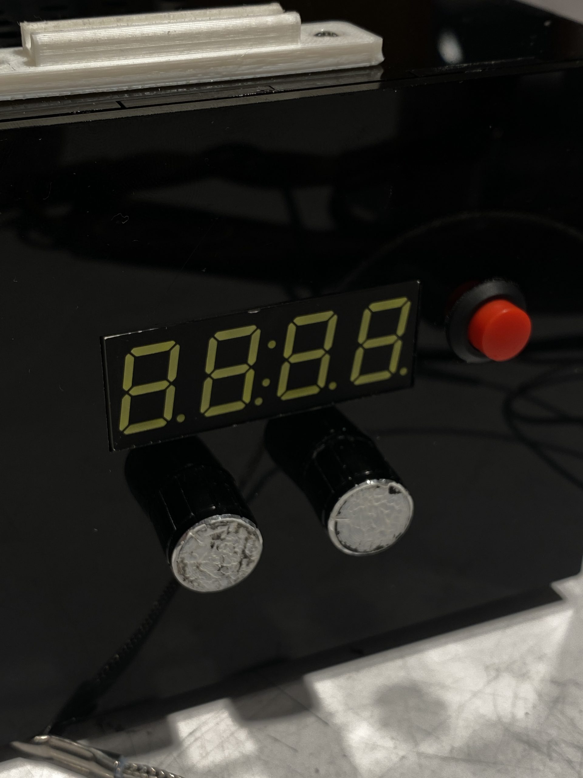
Our project is an assistive device designed to help our client Bill with his cooking activities. As mentioned, Bill has achromatopsia and is sensitive to light, which makes it difficult for him to determine if meat is cooked through due to his inability to see color changes. To address this challenge, our device has two systems. The first system is a temperature sensing system that allows Bill to input the desired cooking temperature using a keypad. The device will then display both the set temperature and the current temperature detected by the probe on two seperate screens. The second system is a timer that countdown the cooking time for Bill’s dish and alerts him when it’s completed. Together, these two systems help Bill cook safely and confidently without worrying about undercooked or overcooked meat.
“Story”
Bill wakes up early on a Sunday morning feeling energized and ready to cook up a storm in the kitchen. He decides to make a special breakfast of pancakes and bacon, and he can’t wait to use his new assistive cooking device. He pulls out his ingredients, preheats the stove, and starts cooking the bacon. With his device by his side, he inputs the desired temperature and sets the timer for the bacon. As the bacon cooks, Bill takes advantage of the time to prepare the pancake batter. He uses the probe to check the internal temperature, and the device displays the readings on the screen. The bacon is perfectly cooked, and Bill is thrilled with the results. Next, it’s time to cook the pancakes. Bill sets the temperature for the griddle and starts cooking. He sets the timer for each batch, knowing that he won’t have to worry about overcooking or undercooking them. The device beeps to signal when it’s time to flip the pancakes, and Bill easily flips them. Finally, it’s time to plate the food. Bill arranges the pancakes and bacon on the plate and pours a generous maple syrup. He sits down to enjoy his meal, feeling proud of himself for cooking such a delicious breakfast. Thanks to his new assistive cooking device, Bill can cook safely and confidently without worrying about undercooked or overcooked meat. He feels empowered and independent in the kitchen and can’t wait to try out new recipes with his device by his side.
How we got There
-
Prototype
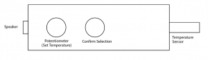
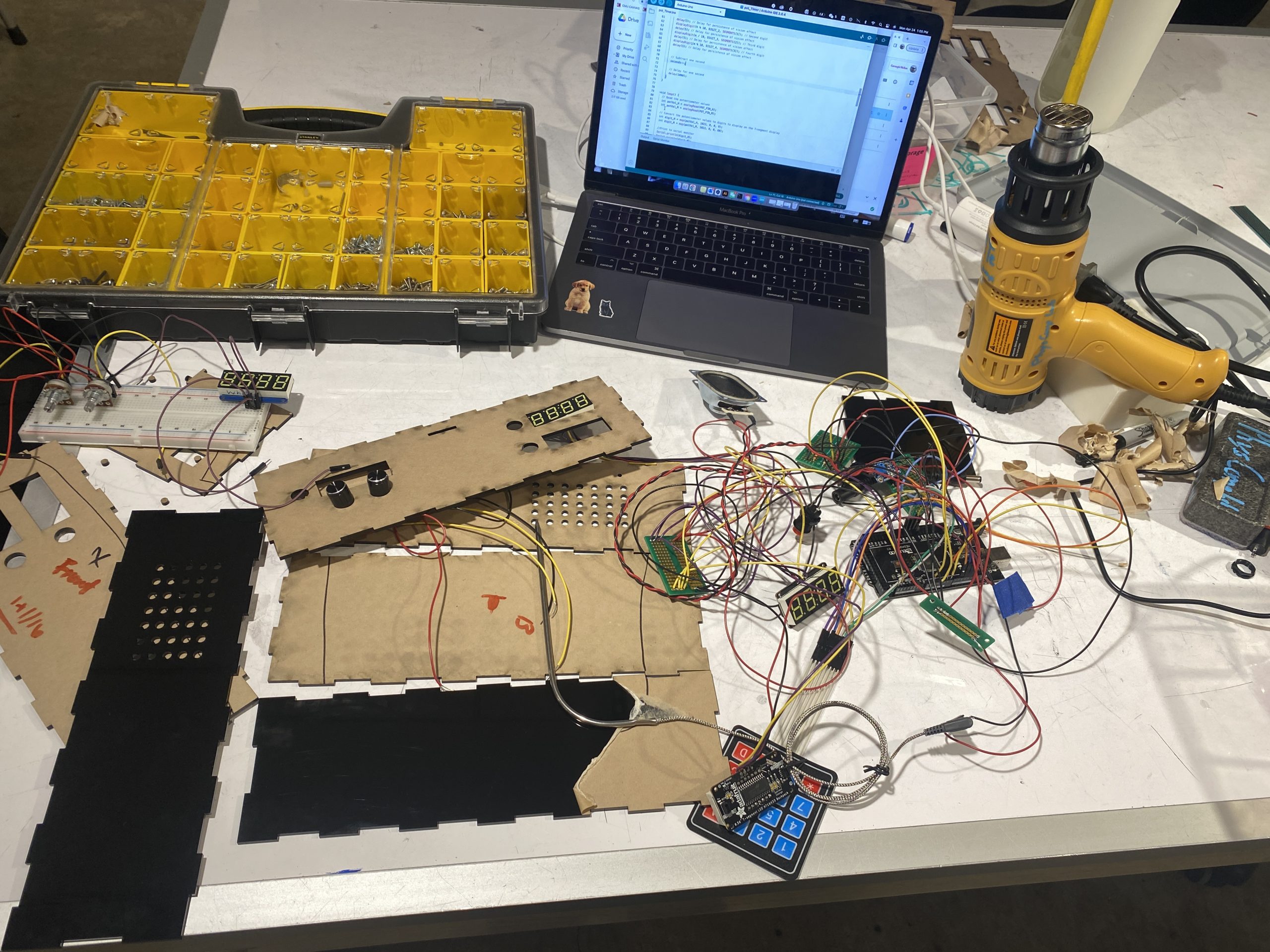
We started by prototyping the inputs and outputs of the meat-cooking assistive device. We were thinking about and exploring how different buttons, screens, LEDs, and temperature sensor work with one another and are housed and interacted with by Bill.
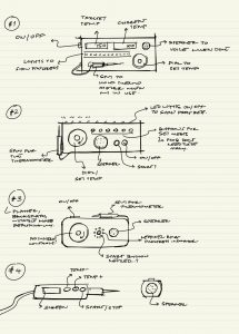
Ideating on the form of the object and how Bill may interact with it.
A version with screen to compliment the voice from the speaker, and a more tangible button system for inputting the temperature.
A version with screen to compliment the voice from the speaker, and a more tangible button system for inputting the temperature.
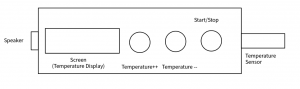
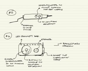
Figuring out handheld versions. Thinking about features it might have and how they may be interacted with.
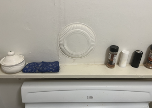
A reference that Bill shared of his kitchen space, and the shelf the device will live on.
After the prototype critique, we asked more questions to Bill because we wanted to design a device that truly fits his preferences. Our questions for Bill after these initial prototypes revolved around:
- Where would he like it? Storage?
- On the countertop
- As a complete object (fully handheld)
- Something that fits in a drawer
- Something that goes on a backsplash
- Should it be wipable/ cleanable?
- What kind of inputs would he prefer?
- More touch screen style
- Different kinds of potentiometers
- Keypad
- The dirtiness of fingers may be a consideration
- Does he want to set each degree of temperature or scroll through a menu?
- Does he want the additional feature of a cooking timer?
- What kind of outputs to tell him that it is ready
- Audio
- Visual? Zach said he had a high screen
- Light? How many bulbs are on kind of thing
Incorporating the feedback we received during the critiques, we made several changes to our design. We added a voice output feature for the current temperature and included a separate timer feature. We also made the box housing generally pretty dark for higher contrast. During the refining process, we asked Bill many questions about his cooking preferences and needs. We learned that while he does cook in a dark kitchen and likes sound output, he prefers to read numbers from a screen. He also mentioned that white text on a black background and a comfortable font size would work well for him. We found a 7-segment number display that would meet his needs and decided to make the housing and aesthetic of the box generally pretty dark to provide higher contrast.
Initially, we had considered including a progress bar or feedback feature to let Bill know how close his meat was to reaching the target temperature. However, Bill said it wouldn’t be something he would particularly need, so we decided to focus on providing him with the current and target temperatures on the two displays instead. Regarding input, we discussed the practicality of a keypad layout and decided to include a little button connecting to the speaker to voice the current temperature when pressed. We also included a separate timer feature with an hour and minute dials and a similar screen and button for voicing the feature.
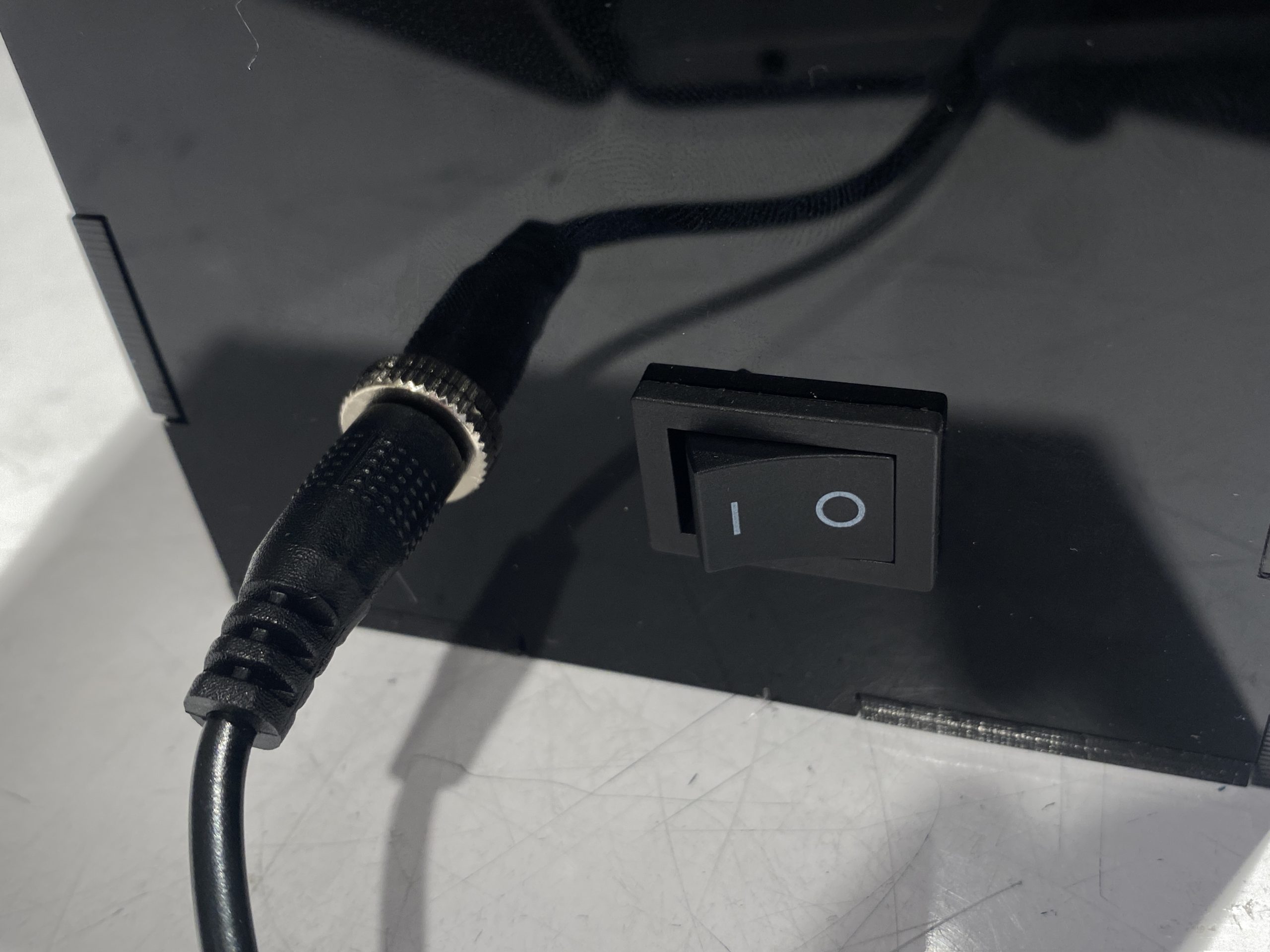
Considering Bill wants to put this device on his shelf above the stove, we designed to used a power cable that allows Bill to plug it in and use the device easily. We also added an on and off switch just in case he doesn’t like to plug in and out every time but still can turn the device on and off.
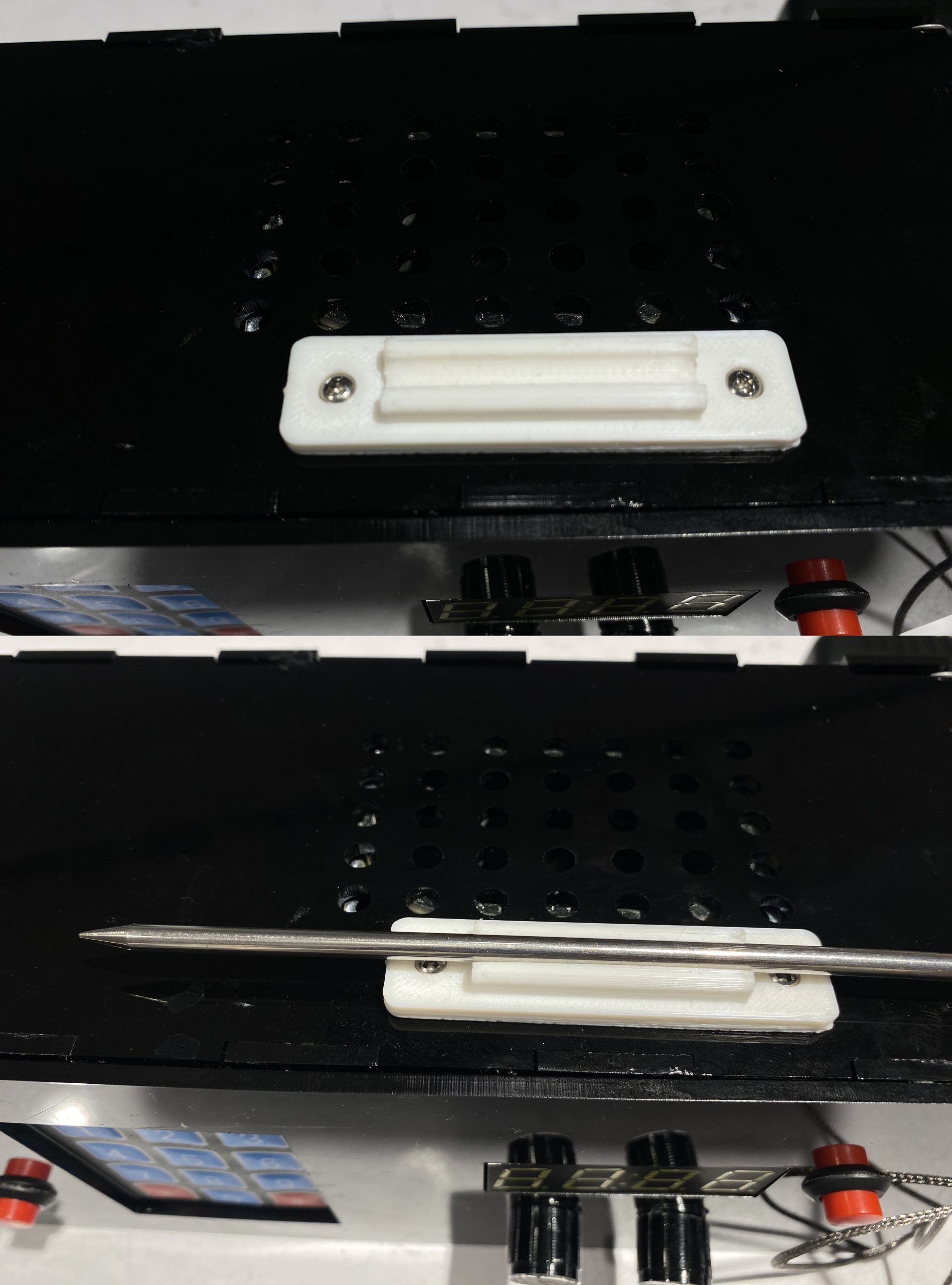
Another feedback we took from the critique is that adding a hinge on the device to organize the probe is necessary. So we 3D modeled and printed a hinge that could exactly hold the probe and mounted it to the top of the device.
-
Process
Our Built process followed our initially outlaid schedule very closely, we did not experience a lot of delays or deviations from the initial design plan aside from the electronics taking 1 day extra to finish and debug.
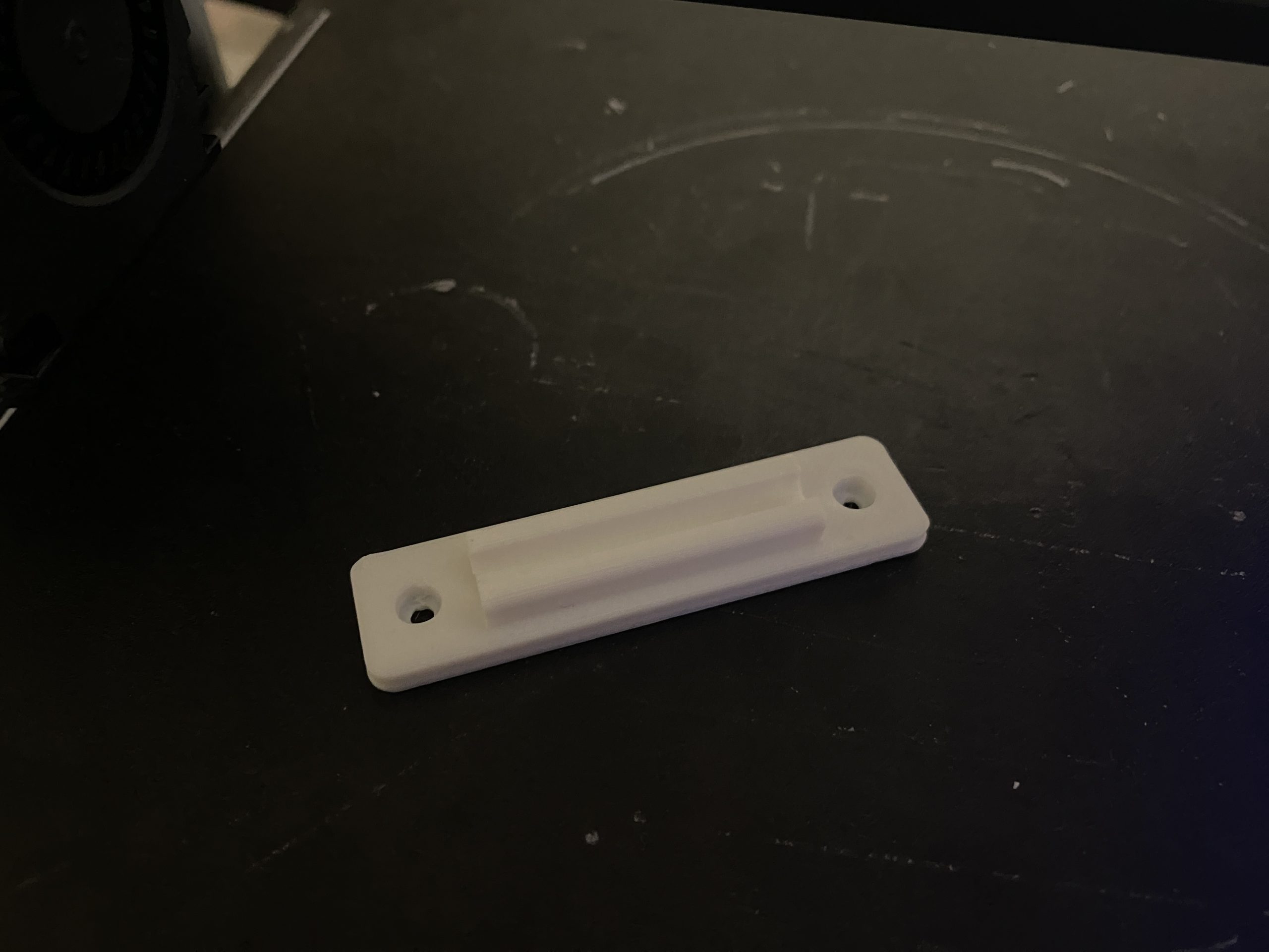
3D Printed Hinge for the thermistor
Laser-cut the box with black acrylic. and soldered electronics placed side by side.
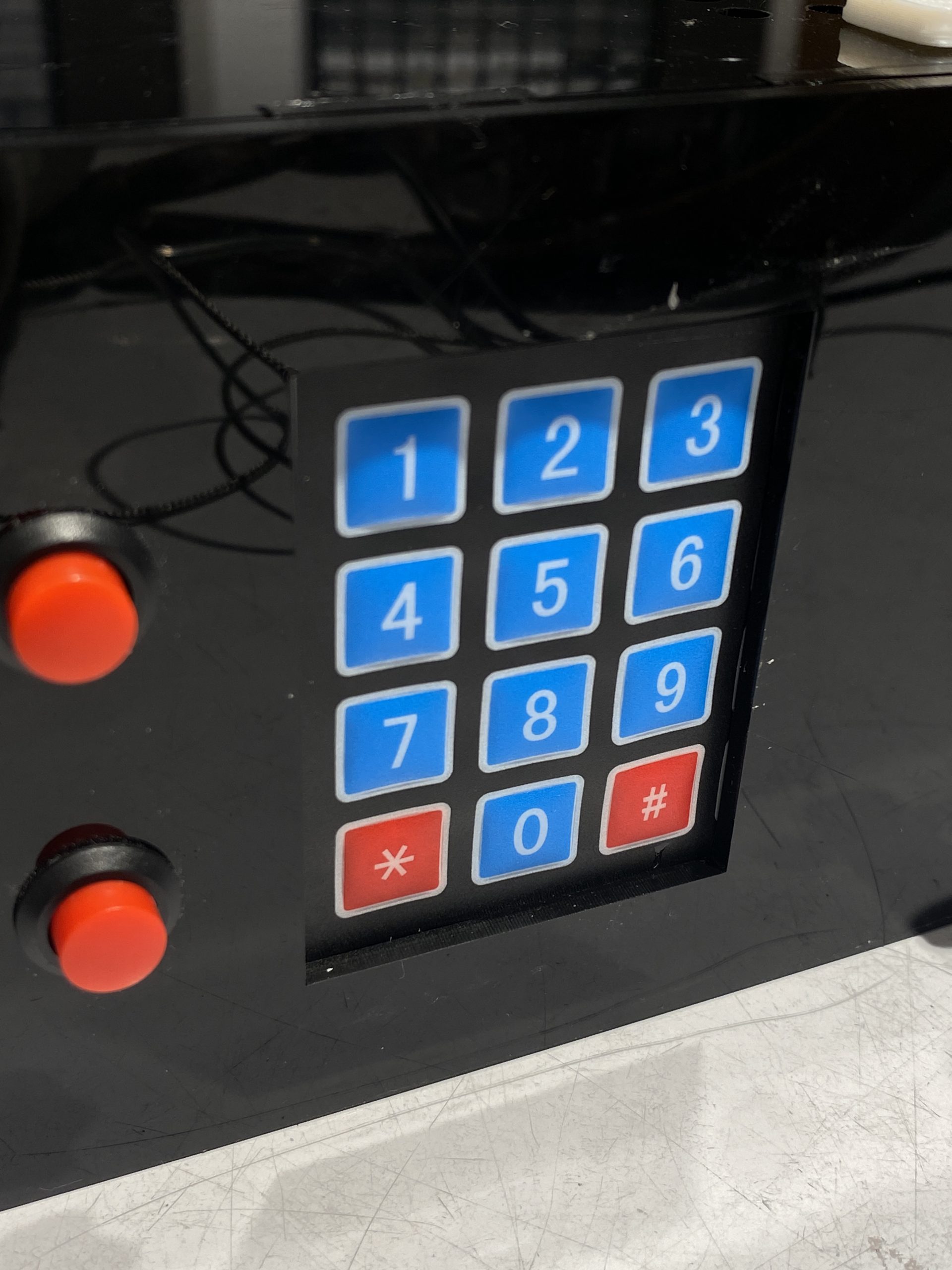
We have a double panel for the front to cover the ‘ABCD’ row of the keypad, which we will not use.
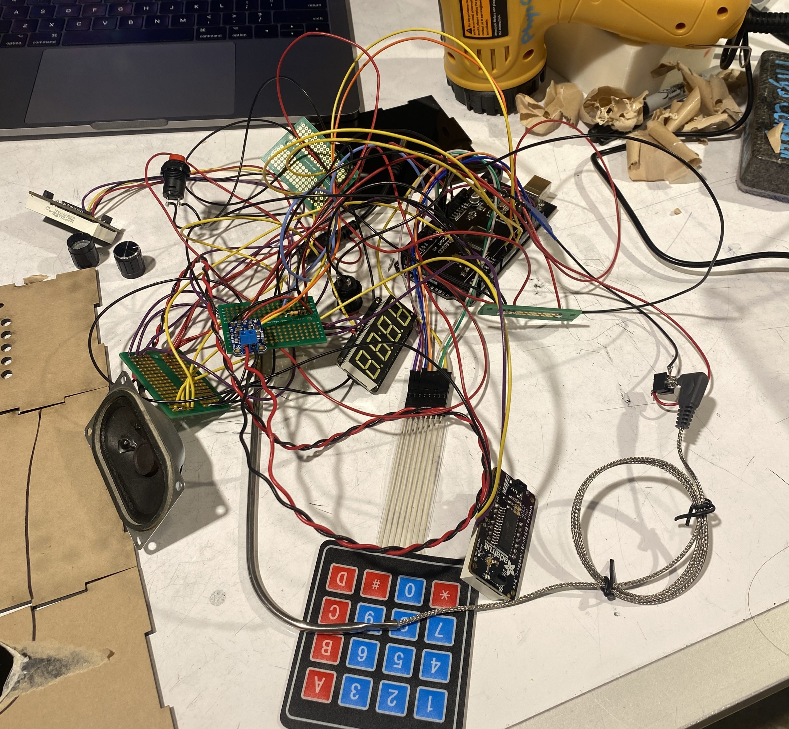 Soldered all electronics together to avoid unstable connections.
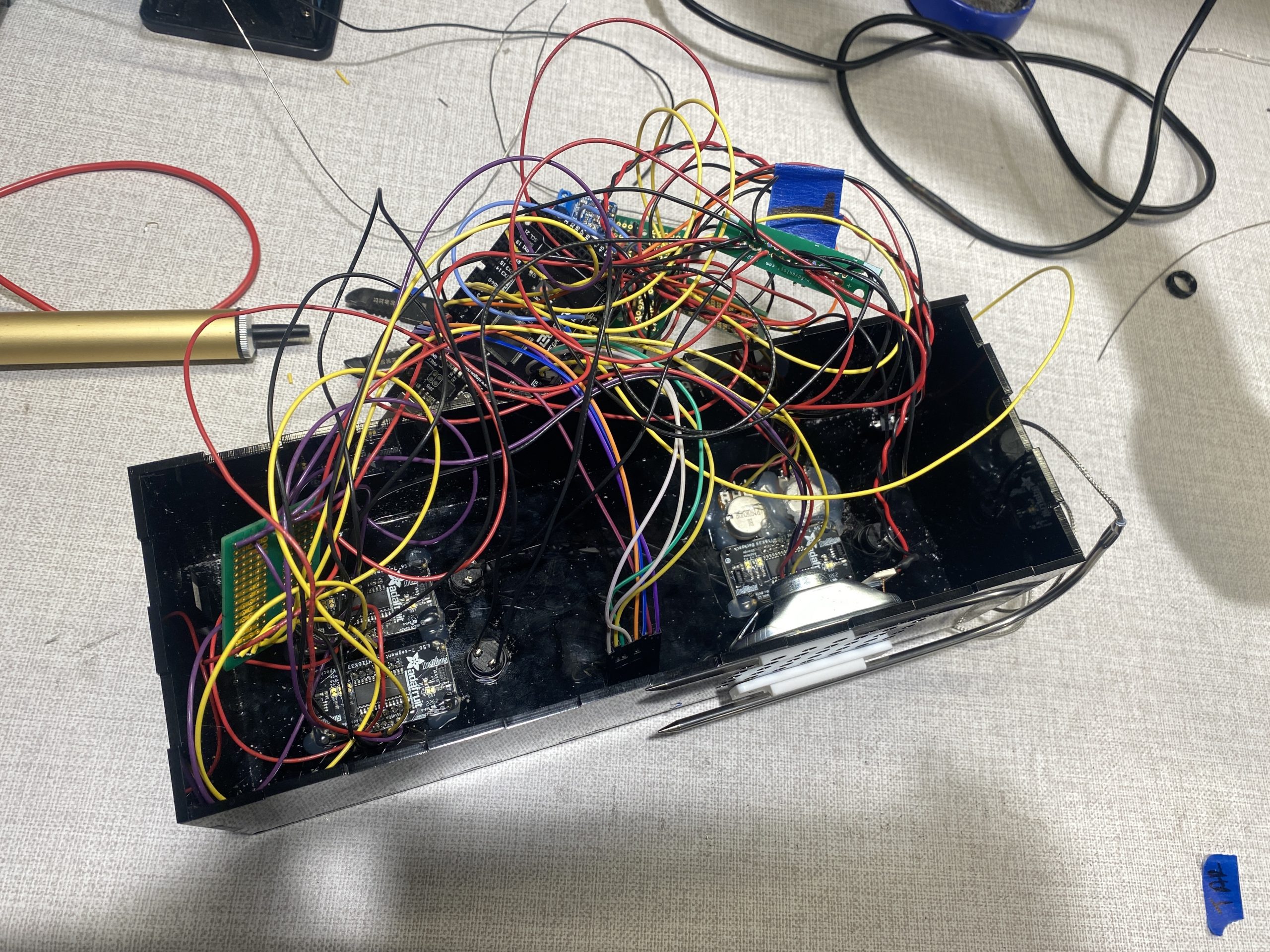 Glue the components on the box.
Overall the build process was what we expected. We stuck closely to our initial design and the electronics cooperated with the vision of our final product. There were a few strange library conflict with our text to speech library but that was debugged rather quickly. All of our box parts fit well and the foresight to use clearly labeled stranded wire made assembly very easy.
Conclusions and Lessons Learned
Starting with the final critique. We were overall pleased with the final presentation and critique of the project. There were some last minute software/ electric related bugs but other than that, our device performed as expected.
The feedback that we received was roughly split into 2 categories: design and execution. The design related feedback was very insightful as at that point in time, we had been staring at this particular design for a couple weeks, having fresh perspectives was nice. Much of the feedback centered around the user friendliness of the design stating that :”Some of the usability was unclear, it could benefit from some labels to clarify what each numbers are corresponding to and a volume potentiometer.
“ and “Would be helpful if the buttons read out their purposes as well as the corresponding figures, as well as having the displays physically labeled”. The core of the feedback that complimented the design on its sleekness and minimal look also criticized the confusing nature of the placement of the buttons. It would probably be a good idea to label the buttons as it does not really detract from the overall look or function of the device. It was an issue of running out of time that we chose not to mess with the overall design too much. In addition, the displays being physically labeled would probably preclude the need for labeling the buttons. We also had a design comment about the placement of the thermometer over the speaker cutout. “Placement of thermometer rest in proximity to speaker holes presents moisture challenges and could be made more ergonomic.” This was very interesting as we had not considered the potential for the thermistor to become wet and leak into the speaker port. Given that both the port and the mount are easily moved. A future interaction would definitely address this. There was also a comment about adding some rubber feet to the device to prevent it from slipping. This would probably be a good idea on a commercial version but we designed the device to fit on a specific shelf where slipping when pushing a button would not cause any problems.
Finally on execution notes. A lot of notes were on the buggy timer and screen flashing which we were aware of potential fixes already. However, there were some software notes that we had not considered. One interesting note is that “Needs warning beeps at T–5°, solid alarm tone at T°, and a constant (but dismissable) BURN ALERT at something like T+10°.” While designing the functionality of the product, we only considered a warning when the temperature was met with the assumption that Bill would be able to head and see it. If it’s the case that he is in another room, we did not consider that possibility. A future iteration would include an approaching temperature chime as well as a burn warning that is sustained in order to address these cases. I think this was just a situation where we did not consider the possibility of him missing the complete chime.
Overall the feedback was very insightful and having many experienced perspectives really helped us understand the advantages and disadvantages of the design choices that we made.
Working with Bill was an overall good experience. We think given that he was the coordinator and CLASS staff, our experience might be different from other groups working with CLASS members. With Bill specifically, something like not being able to see the doneness of meat was not a complication that we had ever considered with color blindness. Having him as a client made us aware of a lot of issues that partial vision deficiency could cause for a person even if it’s not as serious as full blindness. We are grateful for the opportunity to work with him. We also learned valuable lessons working with and interacting with the other clients in the project as well as the CLASS trip. Prior to this project, we did not have a lot of experience interacting with the disabled community and this project gave a lot of insight into their lives and struggles.
Finally, some notes about this project. This project ran smoothly overall and the team worked well together. The division of tasks was more or less equal and people were able to bring their specialized skills to make the project what it was. Given the opportunity to do it again, our process would be very similar. We built it flex time in the event that something went wrong which helped us out a lot in the end. This final project was an excellent close to a very interesting and engaging class.
Technical Details
-
Schematic and Block Diagram

-
Codes
/*
Project Name: Bill's Cooking Buddy Helper
Project Members: Sapna Tayal, Angie (Chuyi) Wang, Harry Ren
Code Author: Harry Ren
- Assistive Meat Thermometer and Cooking timer
- Keypad input for target temperature
- All values displayed on 7 segments and can be read via speaker

Controller: Arduino Mega

Pin Mapping:
A0: Keypad pin 1
A1: Keypad pin 2
A2: Keypad pin 3
A3: Keypad pin 4
10: Keypad pin 5
11: Keypad pin 6
12: Keypad pin 7
13: Keypad pin 8

2: Current Temp Button
3: Target Temp Button
4: Timer Button

A8: Hour Potentiometer Pin
A9: Minute Potentiometer Pin

6: Main Audio Amp Pin
7: Inverted Audio Amp Pin

A10: Temp Probe Pin

Note: all 7 Segment pins connect to I2C Bus (master-slave) System
SDA: 7 Segment main SDA
SCL: 7 Segment main SCL

Portions of code are adapted from the following sources
- https://forum.arduino.cc/t/another-bbq-thermometer-wifi-enabled-with-push-notifications/225467
- https://forum.arduino.cc/t/countdown-timer-and-adafruit-4-digit-7-segment-display-w-i2c-backpack/364882/2
- https://www.instructables.com/Arduino-Text-to-Speech-Converter-Using-LM386-Talki/
relevant functions are credited
code by Harry Ren at Carnegie Mellon University (hjren@andrew.cmu.edu)
released by author to public domain, April 2023
*/


#include <Keypad.h>
#include <OneWire.h>
#include <DallasTemperature.h>
#include "Talkie.h"
#include "Vocab_US_Large.h"
#include <Wire.h>  // Enable this line if using Arduino Uno, Mega, etc.
#include <Adafruit_GFX.h>
#include "Adafruit_LEDBackpack.h"
#include <math.h>

//Lines 12-19 adapted from https://forum.arduino.cc/t/another-bbq-thermometer-wifi-enabled-with-push-notifications/225467/2
float air;          //  temperature
float meat;         //   Unused from sample code
float vin = 4.999;  //  DC Voltage as measured with DMM between +5V and GND
float r2 = 100000;  // Resistance in ohms of your fixed resistor

float A = 0.00004556837992;     // "A" Coeffecient in Steinhart-Hart Equation
float B = 0.0002634285613;      // "B"
float C = 0.00000005286310982;  // "C"

const int sw1 = 2;  //current temp button
const int sw2 = 3;  //tgt temp button
const int sw3 = 4;  //timer button
const int sw4 = 5; //io switch

Talkie voice;  //init speaker

// Define the pins for the 7-segment display: depreciated
const int digitPins[] = { 2, 3, 4, 5 };
const int segmentPins[] = { 6, 7, 8, 9, 10, 11, 12 };

// Define the keypad
const byte ROWS = 4;
const byte COLS = 4;
char keys[ROWS][COLS] = {
  { '1', '2', '3', 'A' },
  { '4', '5', '6', 'B' },
  { '7', '8', '9', 'C' },
  { '*', '0', '#', 'D' }
};
byte rowPins[ROWS] = { A0, A1, A2, A3 };  //keypad pins
byte colPins[COLS] = { 10, 11, 13, 12 };  //keypad pins
Keypad keypad = Keypad(makeKeymap(keys), rowPins, colPins, ROWS, COLS);


Adafruit_7segment mat = Adafruit_7segment();     //curr 7seg
Adafruit_7segment mat1 = Adafruit_7segment();    //tgt 7seg
Adafruit_7segment matrix = Adafruit_7segment();  //timer 7seg

int number = 0;  //curr tgt
int temp = 0;    //curr temp

int startMinute = 4;   //  Modify these defines to
int startSecond = 59;  // change the timer interval
int minutes = startMinute;
int seconds = startSecond;
bool notStarted = 0;  //timer started bool flag

unsigned long previousSecondMillis = 0UL;
long oneSecond = 1000UL;  // milliseconds per second

const int POT_PIN_H = A8;
const int POT_PIN_M = A9;
int digit_H = 0;
int digit_M = 0;


void setup() {

  Serial.begin(9600);

  //init button pins
  pinMode(sw1, INPUT);
  pinMode(sw2, INPUT);
  pinMode(sw3, INPUT);

  //init 7 segments
  mat.begin(0x70);
  mat1.begin(0x71);
  matrix.begin(0x72);
  mat.print(number);
  mat1.print(temp);

  matrix.writeDigitRaw(2,0x2);

  // Set the digit pins as outputs: depreciated
  for (int i = 0; i < 4; i++) {
    pinMode(digitPins[i], OUTPUT);
  }

  // Set the segment pins as outputs: depreciated
  for (int i = 0; i < 7; i++) {
    pinMode(segmentPins[i], OUTPUT);
  }

//init speaker code: depreciated
#if defined(TEENSYDUINO)
  pinMode(5, OUTPUT);
  digitalWrite(5, HIGH);  //Enable Amplified PROP shield
#endif
}


void loop() {
  //read switches
  int switch1 = digitalRead(sw1);
  int switch2 = digitalRead(sw2);
  int switch3 = digitalRead(sw3);
  int switch4 = digitalRead(sw4);

  //BUTTON CODE
  if (switch1 == 1) {
    readnum(number);
  }
  if (switch2 == 1) {
    readnum((int)air);
  }
  if (switch3 == 1) {
    notStarted = 1;
    //previousSecondMillis = 0UL;
  }


  //TEMP PROBE CODE
  //read and update current temp
  readSensors();
  mat1.print((int)air);

  //KEYPAD CODE
  // Wait for a key press
  char key = keypad.getKey();
  char printednum = '0';
  // If a key was pressed, display and read the corresponding number
  if (key != NO_KEY) {
    int newnumber = getNumberForKey(key);
    saynum(newnumber);
    if (newnumber == 14) {
      number = 0;
      mat.clear();
    }
    //update the 7 seg number
    else if (number < 1000 && newnumber != 14 && newnumber != 15) {
      number = number * 10 + newnumber;
    }
    mat.print(number);
    //Serial.println(number);
  }
  if (switch4==1){
    mat.clear();
    mat1.clear();

  }
  mat.writeDisplay();
  mat1.writeDisplay();

  //TIMER CODE
  //Setting timer
  if (notStarted == 0) {
    int potVal_H = analogRead(POT_PIN_H);
    int potVal_M = analogRead(POT_PIN_M);

    digit_H = map(potVal_H, 1023, 0, 0, 30);
    digit_M = map(potVal_M, 1023, 0, 0, 59);

    startMinute = digit_H;
    startSecond = digit_M;
    minutes = startMinute;
    seconds = startSecond;
    matrix.writeDigitNum(0, (minutes / 10));
    matrix.writeDigitNum(1, (minutes % 10));
    matrix.writeDigitNum(3, (seconds / 10));
    matrix.writeDigitNum(4, (seconds % 10));
    if (switch4==1){
    matrix.clear();

  }
    matrix.writeDisplay();
  }

  else {
    // Countdown timer
    //adapted from https://forum.arduino.cc/t/countdown-timer-and-adafruit-4-digit-7-segment-display-w-i2c-backpack/364882/2
    // --------- Run this every second ------------------
    if (millis() - previousSecondMillis >= oneSecond) {
      //update 7 seg per second
      matrix.writeDigitNum(0, (minutes / 10));
      matrix.writeDigitNum(1, (minutes % 10));
      matrix.writeDigitNum(3, (seconds / 10));
      matrix.writeDigitNum(4, (seconds % 10));
      if (switch4==1){
    matrix.clear();
  }
      matrix.writeDisplay();
      if (seconds-- == 0) {
        if (minutes == 0) {
          //If timer reaches 0
          notStarted = 0;
          voice.say(sp2_COMPLETE);
          //minutes = startMinute;
          //seconds = startSecond;
          delay(1000);
        } else {
          // rollever from n:00 to (n-1):59
          minutes -= 1;
          seconds = 59;
        }
      }

      previousSecondMillis += oneSecond;
    }
  }
}

//reads a 4 dig number on speaker
void readnum(int number) {
  if (number > 999) {
    saynum((number / 1000) % 10);
  }
  if (number > 99) {
    saynum((number / 100) % 10);
  }
  if (number > 9) {
    saynum((number / 10) % 10);
  }
  if (number > -1) {
    saynum(number % 10);
  }
}

//reads a single number
void saynum(int n) {
  switch (n) {
    case 1:
      voice.say(sp2_ONE);
      return;
    case 2:
      voice.say(sp2_TWO);
      return;
    case 3:
      voice.say(sp2_THREE);
      return;
    case 4:
      voice.say(sp2_FOUR);
      return;
    case 5:
      voice.say(sp2_FIVE);
      return;
    case 6:
      voice.say(sp2_SIX);
      return;
    case 7:
      voice.say(sp2_SEVEN);
      return;
    case 8:
      voice.say(sp2_EIGHT);
      return;
    case 9:
      voice.say(sp2_NINE);
      return;
    case 0:
      voice.say(sp2_ZERO);
      return;
    case 14:
      voice.say(sp3_CLEAR);
      return;
    case 15:
      //readnum();
      return;

    default: return;
  }
}


// Convert the key to a number (casting caused problems)
int getNumberForKey(char key) {
  switch (key) {
    case '0': return 0;
    case '1': return 1;
    case '2': return 2;
    case '3': return 3;
    case '4': return 4;
    case '5': return 5;
    case '6': return 6;
    case '7': return 7;
    case '8': return 8;
    case '9': return 9;
    case 'A': return 10;
    case 'B': return 11;
    case 'C': return 12;
    case 'D': return 13;
    case '*': return 14;
    case '#': return 15;
    default: return 0;
  }
}


//Depreciated Function
void displayNumber(int number) {
  int digits[4];
  digits[0] = number % 10;
  digits[1] = (number / 10) % 10;
  digits[2] = (number / 100) % 10;
  digits[3] = (number / 1000) % 10;
}

// Reads and updates current temp
// adapted from https://forum.arduino.cc/t/another-bbq-thermometer-wifi-enabled-with-push-notifications/225467
void readSensors() {
  float a0 = analogRead(A10);                            // This reads the "voltage" value on A0. Value is actually divided into 1024 steps from 0-1023.
  float v0 = a0 * .0049;                                 // Converts A0 value to an actual voltage (5.0V / 1024 steps = .0049V/step.
  float r0 = (((r2 * vin) / v0) - r2);                   // Calculates resistance value of thermistor based on fixed resistor value and measured voltage
  float logr0 = log(r0);                                 // Natural log of thermistor resistance used in Steinhart-Hart Equation
  float logcubed0 = logr0 * logr0 * logr0;               // The cube of the above value
  float k0 = 1.0 / (A + (B * logr0) + (C * logcubed0));  // Steinhart-Hart Equation to calculate temperature in Kelvin
  float f0 = (1.8 * (k0 - 273)) + 32;                    // Convert temperature to Fahrenheit

  if (isnan(f0))  // If value is not a number, assign an arbitrary value
  {
    air = int(1);
  } else {
    air = f0;  // Otherwise use the calculated value
  }
}
]]>
Introduction
For our Intro to Physical Computing class’s final project, our group, the Durians, is working with Bill, an individual from Pittsburgh with Achromatopsia, to develop an assistive device that’s useful and relevant to his experience. To better understand his wants and needs, and get to know Bill better, we conducted an informational interview with Bill. It was conducted via zoom with the members of our group: Sapna, Harry, and Angie. Our goal for the meeting was to gain a better understanding of aspects of Bill’s daily routine, tasks or activities he enjoys doing, and spaces for an assistive device during these.
Meeting Agenda:
Given that Bill has participated in this project before and is the primary liaison for the other clients, we had a relatively straightforward interview plan and anticipated that the interview would run quickly with straightforward answers.
- Introductions: names & background
- Quick rundown of project and purpose
- Bill’s Disability description and history of the disability
- What he struggles with day to day & problems that he has come across as a result of his disability
- Specific instances of struggle with disability
- Something that he wanted to do when he was younger
- What he wants from this project
- What previous groups from this class have done for him
- Any specific requests for devices (since he knows the project pretty well)
- Next steps
Meeting summary and major takeaways:
About the Disability: From the interview, we learned a lot about Bill’s Disability. He has severe light sensitivity and took the meeting in the dark in his house. He expressed discomfort in rooms with bright ambient light, especially outdoors in sunlight or looking at a bright screen. He is also legally blind with 20/200 vision which makes facial recognition, and looking at text at distances difficult. Finally, He has Achromatopsia. Which is full color blindness.
These vision problems were birth conditions so he has lived with these all his life. He recalls challenges from growing up like wanting to be able to play baseball but not being able to see pitches clearly.
Bill seems to have the most day to day complications with issues pertaining to color. He told us that the previous IDEATE team built a clothing color identifier to help him select his wardrobe. He explicitly wanted to address an issue he has with cooking with color blindness.
Since he cant see colors, it is impossible for him to tell the doneness of meat. He would like something to help identify when meat is cooked through appropriately. Here is a quick sketch of a potential devices from the meeting:
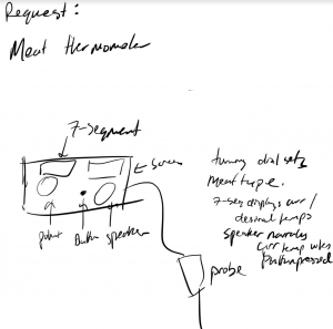
Rough sketch of Meat Thermometer Device
As a quick aside from the project, Bill mentioned that one of the important things he wants us to take from this project is experience interacting with the disabled community. We hope that this experience, along with class visits to CLASS and interacting with other clients gives us this opportunity to experience a subset of the community that is often marginalized and overlooked.
Thoughts and Discussions
- The overall interview experience was smooth. Bill is well spoken and has plenty of experience with this project.
- The conversation was good. We got mostly all the basic information we needed to start our ideation. But we may need more specific information from Bill, for example, the specific value of screen/daylight he is sensitive to.
- Bill seemed pretty set on an idea of something that we could do that interacted specifically with his disability. In hindsight, we probably should have also focused on general assistive devices that could help with quality of life improvements, not just vision based devices.
- We intend on following up with him with alternate ideas that we came up with not related to color blindness.
- Our group had a team member shuffle, we will likely contact Bill again with the full team in order to catch everyone up
]]>
This is a wearable piece that includes a pair of glasses that can change the opacity of the lens and a little installation that can be attached to clothes and will display text and make sounds when the sensor senses things within its range.
Overview
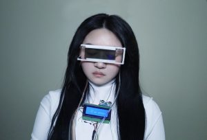 The lens is transparent when there is no one within 50 cm;
and the LCD screen displays”Hi. Do not approach”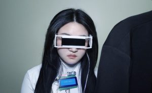 The lens becomes dark when someone is standing within 50 cm;
and the LCD screen displays “!!!STEP BACK!!!”
Simulation of you walking up to a person wearing this device
This is a jacket on a hanger. The glasses’ lens will become dark when the distance is within 50cm, just like what happens in the photo above.
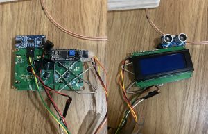
The overall device. (I don’t have anyone with me, so I have to put it on a table and record this. )
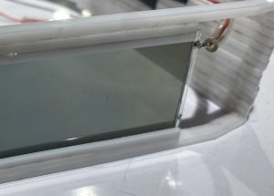
Detail of the device:
The glass frame has an angle and a rail that allows me to slide the lens in simply if I need to change the lens.
Background
This is an assistive device for me.
First, it’s about social distance. I feel that the term “social distance” was used everywhere during the pandemic. During that time, most of us were used to keeping our distance from others. But as we are now in the post-pandemic era, I don’t see a lot of people still maintaining social distance now. However, I still like to keep a certain distance from other humans in social situations. I also sometimes find it difficult to interact with people at a close distance, especially at social events.
The reason is probably that I read a novel called “No Exit” by Jean-Paul Sartre, a French playwright. He proposed a derived philosophical theory called “others are hell.” This sentence doesn’t mean that other people are the devil. It means that everyone is free without others’ intervention. In the book, Sartre describes four people whose souls have fallen into hell. There is no torture or fire as expected, but only a closed chamber that locks the four people so that whatever they do has to be done in the presence of others. The lights are always on, and the knife cannot kill other people. Sartre considered such to be the suffering of hell. My understanding is that in such a situation, the gaze of others can influence my free will, shape my choices and cause me pain, especially when I sometimes make choices against my will under the influence of others. I see other people as people that are “not me.” In this case, the difference between “me” and “others” defines the scope of “self.” So, without others, I would not be the person I am now, but the person I am now is in danger of losing my ability to judge and choose freely because of others.
To put it in perspective of vision, human vision is more than simply looking at things. When I look at the outside world as an individual, the world comes together towards me, hence, I am the center of the world, and I am completely free. This gives rise to a transcendence, meaning that I am subjective, which is also called the ‘subject self’ by Sartre. But when in groups or in public, all my activities will be branded with the shadow of others, and I will find myself gazed at by others. I then will degenerate under the gaze of others because I take the gaze of others as my own possibility in my activity. This is also an alienation, an objectification, and a deprivation of freedom and transcendence as a subject. Thus the ‘subject me’ becomes the ‘object me,’ and the OTHERS become the subject in my eyes. The “my world” built up by my perspective collapses, and this is the so-called “other is hell.”
If we reflect this theory into reality, I think people become “objects” when they interact with each other in any form, for example, eye contact or conversation. I don’t want to lose my subjective self in social and public events, so I thought of making this device. Basically, there is an ultrasonic ranger on the installation that can be attached to clothing. This is to sense the distance. When no one is in my social comfort zone (50cm), the lens of the glasses (light valve) is clear, like normal light-colored indoor sunglasses, and the LCD screen will display “Hi. Do not approach”. But when someone steps into my social comfort zone, the lenses of the glasses will darken, basically impossible to see through, and the device that is attached to the clothing will start going on an alarm. The text on the screen will change to a flashing “!!! STEP BACK!!!”. This device is also an artificial social shield for me.
Process
Decision 1:
I spent a lot of time thinking and experimenting with two kinds of sounds for a ‘warning sound.’
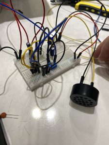
- Use a buzzer. This will create a sound that really sounds like a warning. but people may wonder if there’s anything bad happening.
- 2. Use a speaker that plays my own voice saying “Step back.” This fits my ideation more; however, as I tested it with my friends, I got feedback like “I heard Angie’s voice, so I want to come closer.” This totally contradicts my intention. But I found it interesting that sometimes the result will be different from my ideation until I really experiment with my design with people.
 I finally decided to use the buzzer because it is small so it can be glued to the back of the screen together with the ultrasonic ranger. Most importantly, it turns out to be less attractive than using my own voice.
Decision 2:
For the glasses’ frame, I want it to have a futuristic look like the 3D model I made, ideally.
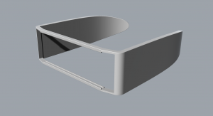
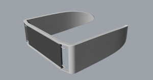
The modeling process took a very long time because this was my first time using Rhino to build a 3D model.
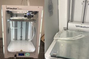
I initially wanted to use 3D printing because the nylon material is more suitable for a wearable device since it can bend a little. However, the 3D printer failed my printing several times, and almost 20 hours were wasted.
These are pictures of the first and second time of printing failures.
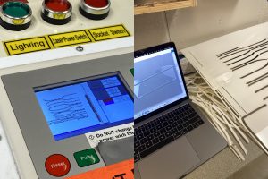 So, Cody suggested and helped me a lot to use the laser cutter instead. Since I have never used a laser cutter before, I also spent time learning how to operate the machine and put the parts together.
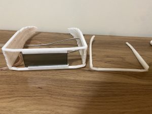
But the dimension of my model is wrong when the software automatically converts the 3D model to the slices. The original dimension of the frame should exactly fit my head. And the failed 3D printing actually fits according to my original dimension. However, the laser-cut pieces turned out to be much bigger than the dimensions I set. This also resulted in I had to hold the glasses during the showcase. The frame on the right is the 3D printing (third failed version), and the one much bigger on the left is the laser cutting version.
Discussion
I prefer to call it my work rather than a project. The idea of my creation has always been to do something meaningful. For example, this work combines the philosophical theory of Sartre while curing my fear of social interaction. So in a macro sense, I am satisfied with it.And I like the process of me brainstorming about things.For example, the futuristic glasses reminded me of my other work about bionic robots. So when I was finishing the wiring, I thought of wrapping the wires with soft pipes. This not only solves the problem of messy wiring but also leads me to think about another possibility: what if a bionic robot were to wear the device? Can these wires be plugged directly into its body? Maybe this can be a way to train it to learn and ‘feel’ like a real person, a person that has problems socializing with other people.
However, there are still some regrets about this work, such as the fabrication part. In fact, the final version of laser cutting is not quite what I wanted in mind. And the size of the cut is not the same as the one I measured, so the work is not perfect. But anyway, I think this is a good start, and I am grateful for everyone’s help. I have never used laser cutters and 3D printers before, so I learned a lot of skills from quick learning and operation this time.
I also received a lot of meaningful feedback. One is about the choice of sound that the device would make when people are getting closer. This is also one of the most tangled questions during the process. It is interesting to hear that different people have different suggestions and preferences on sounds choice. Some say that they would be attracted more by the buzzer sound, while some say they definitely will come closer and take a look if it is displaying a sound of me or a robot. I think this is something associated with psychology and sociology. I definitely would dig into related research and see which way may fit my concept better. Another interesting piece of feedback is from one of the faculties. He commented that maybe it would be better to create a device that could make me invisible in public places. But I thought about it for a long time, and I think that this is not the best solution for me. I think my main point is to avoid social interactions that make me uncomfortable, like getting too close, rather than hiding myself completely. When others step into my comfort zone, even if I don’t want to be forced to be an “object, I am physically present in the world, so I have no right to prevent anyone from gazing at me or interacting with me. This is their freedom. All I can do is shield myself and avoid interactions. After all, all I want is to remain my own self when socializing, and perhaps choosing to avoid unnecessary interactions is also a manifestation of the subjective self.
Technical information
Block Diagram:

Schematic Diagram:

Code
// My Social Shield
// Angie (Chuyi) Wang
// This code allows you to make a sound with a buzzer, display different texts on an LCD screen and control the transparency of
// a light valve while the ultra sonic ranger detects the distance.
//For the light valve, one wire goes to the GND and another wire must be connected to analog pin. (I used A0)
// References: https://courses.ideate.cmu.edu/60-223/s2023/tutorials/I2C-lcd
//             https://www.instructables.com/How-to-use-a-Buzzer-Arduino-Tutorial/

#include <Wire.h>
#include <LiquidCrystal_I2C.h>

#define trigPin 10
#define echoPin 13

#define LIGHTVALVE A0
int brightness = 0;
int fadeAmount = 5;

const int buzzer = 7; //buzzer to arduino pin 7
long transparency;


// Set the LCD address to 0x27 for a 20 chars and 4 line display
LiquidCrystal_I2C lcd(0x27, 20, 4);


void setup() {
  Serial.begin (9600);
  pinMode(trigPin, OUTPUT);
  pinMode(echoPin, INPUT);

  pinMode(buzzer, OUTPUT); // Set buzzer - pin 7 as an output
  pinMode(LIGHTVALVE, brightness);
  lcd.init();
     lcd.begin(10,2);
}

void loop() {
  float duration, distance;
  digitalWrite(trigPin, LOW);
  delayMicroseconds(2);

  digitalWrite(trigPin, HIGH);
  delayMicroseconds(10);
  digitalWrite(trigPin, LOW);

  duration = pulseIn(echoPin, HIGH);
  distance = (duration / 2) * 0.0344;

  int d1 = distance;
  // mapping the distance to brightness
   if(d1 > 90){
     d1 = 90;
   }

  // analogWrite(LIGHTVALVE , brightness);
  brightness = map(d1, 0, 90, 255,0);
  analogWrite(LIGHTVALVE,brightness);

  lcd.clear();

 // delay(100);
  if (distance >= 50 || distance <= 2){
    Serial.print("Distance = ");
    Serial.println("Out of range");
   // Serial.println(distance);
    //panelState = 0;
    brightness = 0;
    // delay(1000);
    //analogWrite(d1 , LIGHTVALVE);

    	// Turn on the blacklight and print a message.
    lcd.backlight();
    lcd.setCursor(4,1);
    lcd.print("HI.");
    lcd.setCursor(4,2);
    lcd.print("DO NOT APPROACH.");
    delay(500);

  }
  else {
    lcd.backlight();
    lcd.setCursor(1, 5);
   // lcd.clear();
    lcd.print(" !!!STEP BACK!!!");
    //print distance to serial
    Serial.print("Distance = ");
    Serial.print(distance);
    Serial.println(" cm");
    delay(200);

    //Buzzer
    tone(buzzer, 1000); // Send 1KHz sound signal...
    delay(500);        // ...for 1 sec
    noTone(buzzer);     // Stop sound...
    delay(200);        // ...for 1sec

    //change the transparency
    // analogWrite(LIGHTVALVE , brightness);
    brightness = brightness + fadeAmount;


  }

}
]]>